Contents hide
AV LINK HDM-3EXCU 100M + USB HDMI UHD Extender
Package Contents
- 2x HDM-3EXCU or HDM-3EXC or HDM-3MXCU or HDM-3MXC Unit
- 1x User manual
- 1x USB Micro B to Type A Cable ( HDM-3EXCU HDM-3MXCU Only )
- 1x IR Receiver Cable
- 1x IR Blaster Cable
- 2x Terminal Blocks 3P
- 1x Power adapter DC 12V with lock
Anything missed, please contact with your vendor.
Features
- Through the HDMI Extender, you can use one BD or UHD Source to display identical image and extensions of HDMI signal up to 100 Meter on UHD TV.
- HDCP Compliant
- Supports 3D pass-through
- Support RS-232(Bi-direction transfer)
- Supports all frequency band IR extension control
- One CAT.6A U/FTP cable extension *Note
- Supports UHDTV up to 4k2k@60 4:4:4 & HDR
- HD-BaseT technology
- USB 2.0 Extender
- Supports Power over Cable ( POC ) *Note
Specifications
| Function | HDM-3EXCU | HDM-3MXCU | HDM-3MXC |
| HDMI In Connector | HDMI A-Type Female x 1 | ||
| HDMI Out Connector | HDMI A-Type Female x 1 | ||
| RJ-45 Connector | 1 | ||
| RS232 | Terminal block (TXD GND RXD) | ||
| IR OUT | 3.5ψ Stereo Jack x 1 | ||
| IR IN | 3.5ψ Stereo Jack x 1 | ||
| USB Micro B | USB 2.0 ( Host or Device ) | USB 2.0 ( Host or Device ) | NA |
| DIP SW | Setup USB/IR/Gender Function | ||
| Max. Resolution | 4k2k 60fps 4:4:4 / 8K 30fps 4:2:0 | ||
| Cable Distance | Cat.6A U/FTP 100M | Cat.6A U/FTP 40M | Cat.6A U/FTP 40M |
| Power Adapter (Min.) | DC 12V with lock | ||
| Housing | Metal | ||
| Weight | 228 g | ||
| Dimensions | 107.2 x 69 x 20 mm (LxWxH) | ||
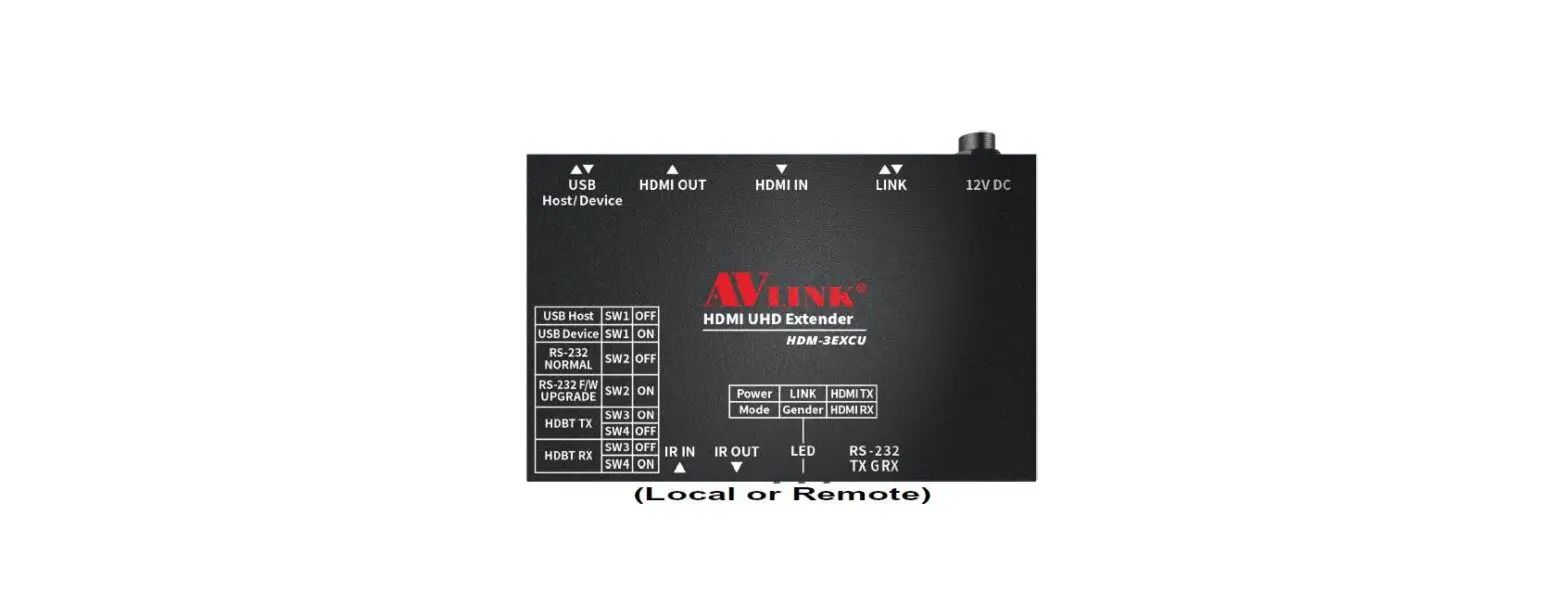
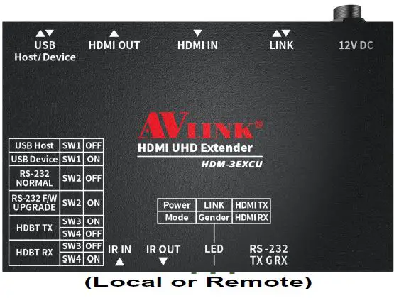
LOCAL FRONT VIEW 
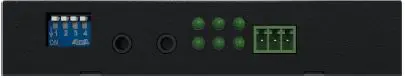
- DIP SW : USB/RS232/Gender Device Setup
- IR IN
- IR OUT
- LED: Power/Mode/LINK/Gender/HDMI TX/HDMI RX
- RS232 : TX/GND/RX
LOCAL REAR VIEW 
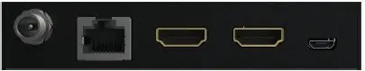
- Power Jack
- LINK: HDBT TX/RX
- HDMI IN
- HDMI OUT
- USB : Host/Device ( 3EXCU & 3MXCU Only)
Installation
- Connect the HDMI extension cable between the BD and the “HDMI IN” port of HDM-3EXCU Local TX Device.
- Connect the HDMI extension cable between the UHDTV and the “HDMI OUT” port of HDM-3EXCU Remote RX Device.
- Connect the CAT.6A cables between the TX “LINK” port and the RX “LINK” port of extender.
- Connect the power cord on the extender.
- Turn on the BD UHDTV and Power on HDM-3EXCU.
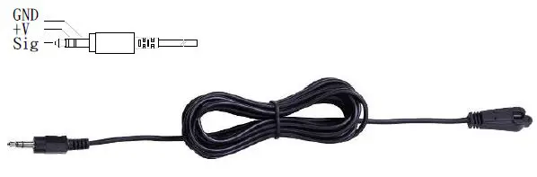
IR Receiver Cable Directions:
Put it into the Device “IR IN” port and place the IR Receiver Cable, so that you can point to it easily with your IR remote extension controller.
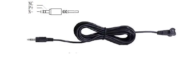
IR Blaster Cable Directions:
Plug IR blaster cable plug into Device “IR OUT” port, It sits in front of the BD receiver’s IR sensor, which is located on the front panel.
RS232:
- Connect RS232 signal to RS232 TXD/GND/RXD Port on HDM-3EXC TX and RX Device.
- RS232 baud rate support to 115200.
USB
- Setup the HDM-3EXCU Dip SW to USB Host or Device.
- Connect Cable between the PC and HDM-3EXC USB Host Port.
- USB Micro B to Type A Cable Connect to HDM-3EXCU USB Device Port and Plug in USB Device on Cable Type-A Port.
- Support Keyboard/Mouse/Flash Drive and many more USB 2.0 Devices up to 350Mbps data rate.
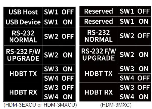
Dip Switch Setup 
Led Status
| Power | ON | Power On |
| OFF | Power Off | |
| Mode | Blinking | FW loaded and running |
| LINK | ON | HDBT LINK |
| Blinking | HDBT LOW POWER MODE | |
| OFF | NO HDBT LINK | |
| Gender | ON | HDBT TX |
| Blinking | HDBT RX | |
| HDMI TX | ON | HDMI With HDCP |
| Blinking | HDMI With Out HDCP | |
| OFF | NO HDMI Video | |
| HDMI RX | ON | HDMI With HDCP |
| Blinking | HDMI With Out HDCP | |
| OFF | NO HDMI Video |
Additional Options
Select any additional options you may require.
- IR Receiver Cable

- IR Blaster Cable

Technical Specifications Output Signal 
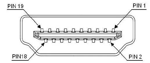
| Pin # | Signal | Pin # | Signal |
| 1 | TMDS Data 2+ | 11 | TMDS Clock Shield |
| 2 | TMDS Data 2 Shield | 12 | TMDS Clock – |
| 3 | TMDS Data 2- | 13 | CEC |
| 4 | TMDS Data 1+ | 14 | Reserved (N.C. on device) |
| 5 | TMDS Data 1 Shield | 15 | SCL |
| 6 | TMDS Data 1- | 16 | SDA |
| 7 | TMDS Data 0+ | 17 | DDC/CEC Ground |
| 8 | TMDS Data 0 Shield | 18 | +5 Power |
| 9 | TMDS Data 0- | 19 | Hot Plug Detect |
| 10 | TMDS Clock+ |
Wiring Information & Coding
| Conductor Identification | RJ45 Pin Assignment | Color Code for Conductor |
| Pair 1 | 5 | White-Blue |
| 4 | Blue | |
| Pair 2 | 1 | White-Orange |
| 2 | Orange | |
| Pair 3 | 3 | White-Green |
| 6 | Green | |
| Pair 4 | 7 | White-Brown |
| 8 | Brown |
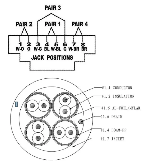
Note:
- The actual transmission quality of CAT6A U/FTP cable will affect the maximum transmission distance. CABLE COMPOSITION: 23AWG*4P CAT6A U/FTP 500MHZ Attenuation : 39 (dB/100m)
- The POC will be attenuated by the actual matching of the CAT6A Cable, which affects the stability of the remote power supply.
Reducing the length of the wire or increasing the CAT6A AWG can increase the stability of the remote power supply.
© AV LINK GROUP LTD., All rights reserved.
Trademarks:
All the companies, brand names, and product names referred to this manual are the trademarks or registered trademarks belonging to their respective companies.


