UFACTORY xArm Linear Motor
General Presentation
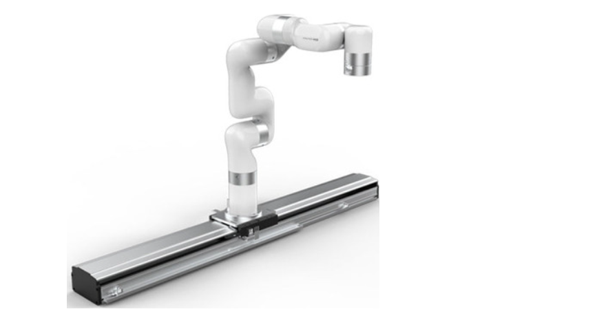
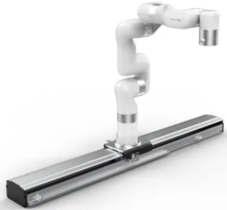
UFactory Linear Motor Introduction
UFactory Linear Motor needs to be used with AC Control Box Pro, it mainly supports and guides the moving parts(Robotic Arm) to move smoothly according to the given direction, which significantly increases the working range of xArm. U Factory Linear Motor
Linear Motor Model
There are two models of UFactory Linear Motor, which can be divided according to Serial Number(SN). SN can be found at the end plate of Linear Motor, see the figure below.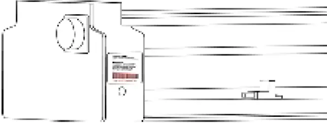 Zero Position: position – 0.
Speed Range: 1 to 1000(mm/s).
Position Range: depend on the model(SN) of Linear Motor.
SN – AL1300: 0 to 700(mm)
SN – AL1301: 0 to 1000(mm)
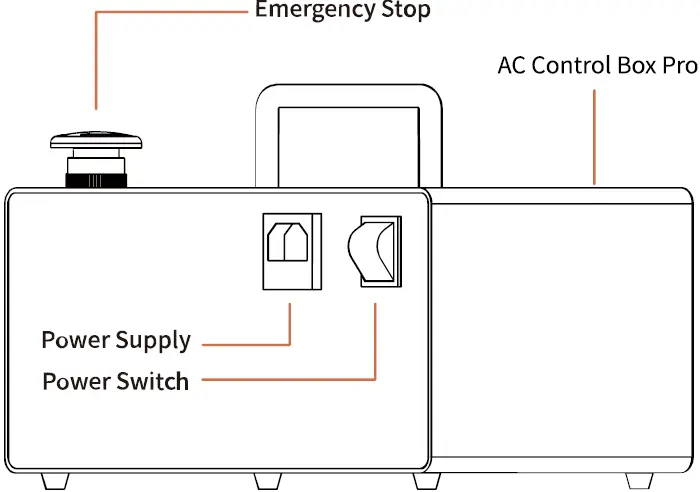
AC Control Box Pro
UFactory Linear Motor comes with AC Control Box Pro.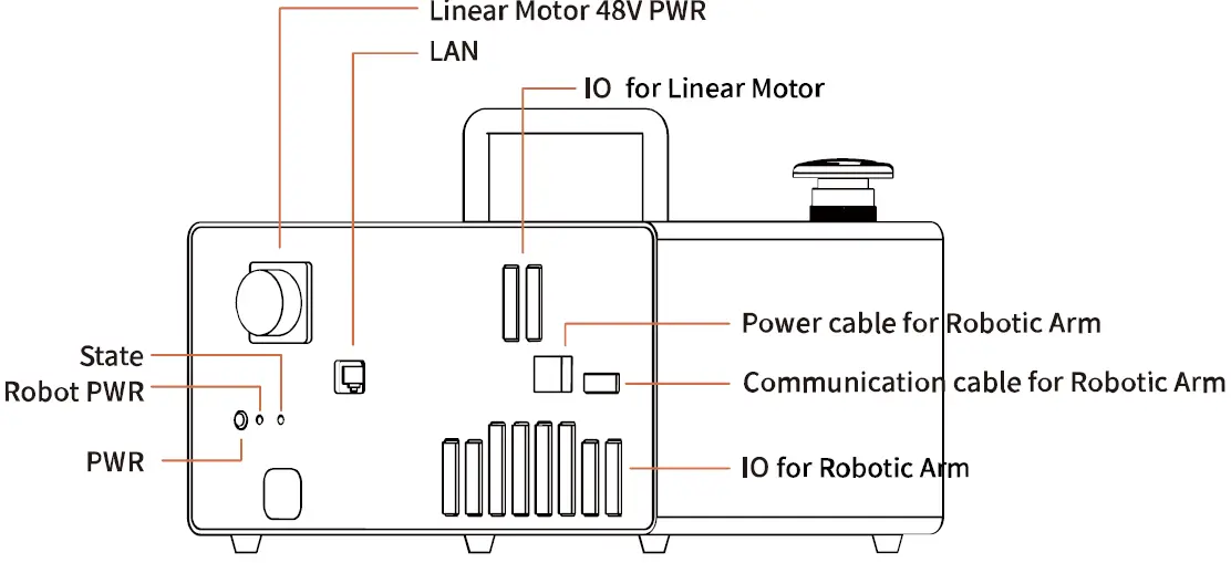
 Control IO connection is as shown in the figure below, and it has been connected before shipping.
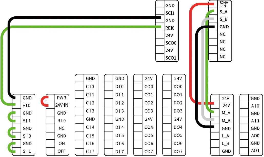
Safety
The operator must read and understand all the instructions below before running the Linear Motor.
Warning
- The Linear Motor needs to be properly installed before operating.
- Do not install or operate a Linear Motor that is damaged or lacking parts.
- Never supply Linear Motor with an alternative current (AC) source.
- Make sure all cord sets are always secured at both ends, Linear Motor end & Robot end.
- Always satisfy the recommended Mechanical Installation.
- Be sure nothing is in the robot and Linear Motor path before initializing the Linear Motor.
- . Set the Linear Motor speed and position accordingly, based on your application.
Caution
The term “operator” refers to anyone responsible for any of the following operations on the Linear Motor:
- Installation
- Control
- Maintenance
- Inspection
- Programming
- Decommissioning
This documentation explains the various components of the Linear Motor and general operations regarding the whole life-cycle of the product from installation to operation and decommissioning. The drawings and photos in this documentation are representative examples and differences may exist between them and the delivered product.
Risk Assessment and Final Application
The Linear Motor is meant to be used on an industrial robot. The robot, Linear Motor and any other equipment used in the final application must be evaluated with a risk assessment. The robot integrator must ensure that all local safety measures and regulations are respected. Depending on the application, there may be risks that need additional protection/safety measures, for example, the work-piece the Linear Motor is manipulating may be inherently dangerous to the operator.
Validity and Responsibility
The Linear Motor is designed for supporting and guiding the moving parts(Robotic Arm), according to the given direction of smooth reciprocating linear motion.
Caution
The product can be installed horizontally only. No debris should be placed on the surface of the product. The photoelectric sensor on the Linear Motor can not be disassembled. The product is intended for installation on a robot or other automated machinery and equipment.
Info
Always comply with local and/or national laws, regulations and directives on automation safety and general machine safety. The unit may be used only within the range of its technical data. Any other use of the product is deemed improper and unintended use. UFACTORY will not be liable for any damages resulting from any improper or unintended use.
Installation
The following subsections will guide you through the installation and general setup of Linear Motor.
- The Scope of Delivery section
- The Mechanical Installation section
Warning
Before installing:
Read and understand the safety instructions related to the Linear Motor. Verify your package according to the Scope of delivery and your order info.
Have the required parts, equipment and tools listed in the requirements readily available.
Installing:
Satisfy the environmental conditions. Please do not disassemble the photoelectric sensor on the Linear Motor. Do not operate the Linear Motor, or even turn on the power supply, before it is firmly anchored and the danger zone is cleared.
Scope of Delivery
A Linear Motor Kit generally includes these items:
- UFactory Linear Motor *1 (including Power cable for the Linear Motor*1, Power cable for the Robotic Arm*1)
- Power cable for the AC Control Box Pro*1
- Communication cable for the Robotic Arm*1
- AC Control Box Pro*1
- Ethernet Cable*1
- Head hexagon socket screws M6*20 (28)
- Head hexagon socket screws M5*12 (5)
- 5MM L type wrench*1
- 4MM L type wrench*1
- Debugging tool*1(USB to 485 cable)
Mechanical Installation
The Linear Motor is directly connected to the AC Control Box Pro via a cable, which is used for 48V DC power supply and Modbus RTU communication over RS-485.
Linear Motor installation steps (as shown below):
- Move the Linear Motor and robotic arm to a safe position. Avoid touching other equipment or obstacles; Please install the Linear Motor horizontally only, not vertically.
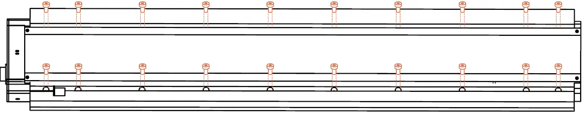
There are 20 φ6.2 screw holes on the linear motor which is designed for fixing the linear motor on the table or base. There are also 28 M6*20 screws in the package.
 Dimension of screws holes in the linear motor (unit: mm)
 - Fix the base plate on the Linear Motor with 8 M6*20 screws.


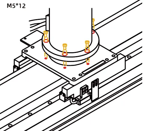
- Fix the robotic arm on the base plate with 5 M5*12 screws.
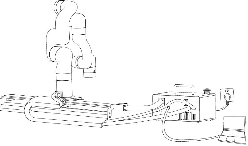
- Cable connection:
- Plug the Linear Motor Power Supply Cable, LAN cable into control box.
- Plug the connector of the Robotic Arm Power Supply Cable and the Robotic Arm Signal Cable into the interface of the Robotic Arm. The connector is a foolproof design. Please do not unplug and plug it violently.
- Plug the Robotic Arm Power Supply Cable and the Robotic Arm Signal Cable into the interface of control box. The connector is a foolproof design.
- Turn on the power switch of the control box and release the emergency stop button.
- Enter into ‘xArm Studio-Settings-Tools-Linear Motor’, click ‘Initialize’ button to return to zero position and finish initialization.

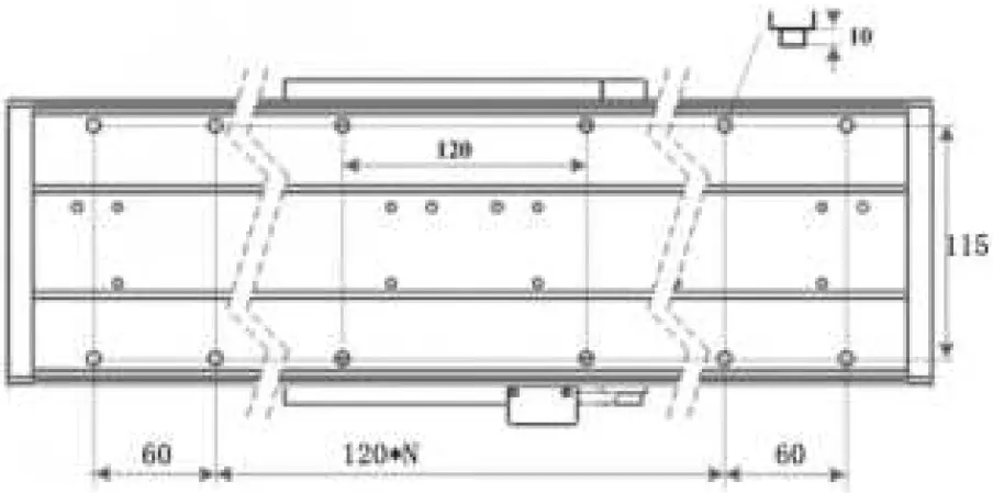 Dimension of screws holes in the linear motor (unit: mm)
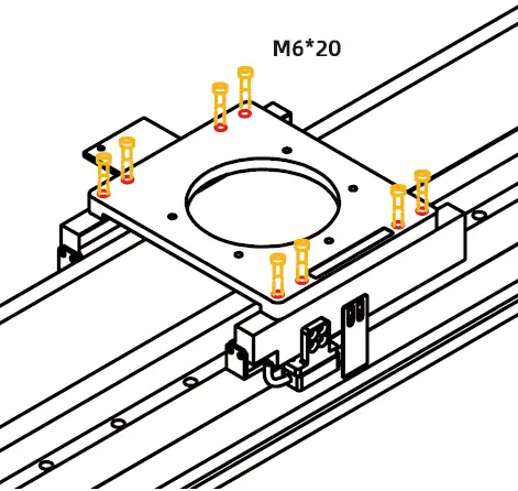
Note:
- When wiring the Linear Motor connection cable, be sure to power off the Robotic Arm, the emergency stop button is pressed down and the power indicator of the robotic arm is off, so as to avoid robotic arm failure caused by hot plugging;
- The Linear Motor has no brake design, please installed horizontally only.
Control
Control Linear Motor through xArm Studio
- Set up Linear Motor
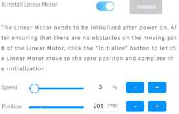
Enter [Settings]-[Tools]-[Linear Motor]
Turn on [Is Linear Motor installed].
Click [Initialize] button.
- [Is Linear Motor installed] button should be turn on.
- Click [Initialize] button to enable the Linear Motor and return to zero position. After the initialization is completed, the Linear Motor will be ready to move.
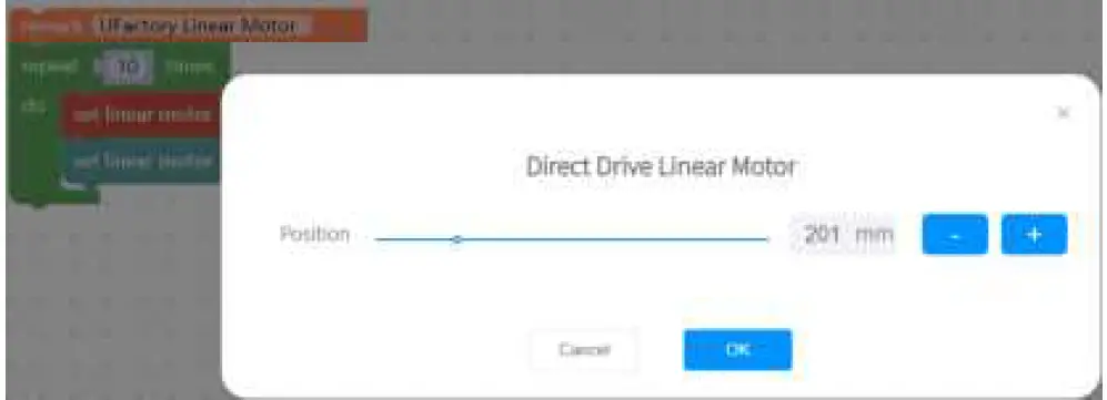
- Control Linear Motor

- In Linear Motor interface, the speed and position of the Linear Motor can be adjusted through the progress bar, +/- keys, and input box.

- Control the Linear Motor through Blockly
UF_Linear_Motor.Blockly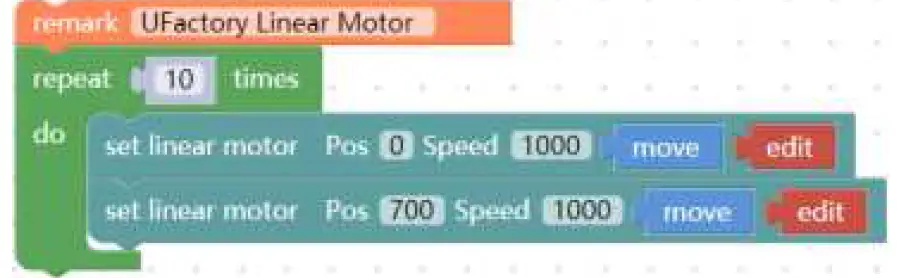 The role of this program: execute this program to control the Linear Motor to reciprocate 10 times at the highest speed(1000mm/s) from the zero position to the farthest position.
Note:
- Before moving the linear motor for the first time after power on, it is a must to go back to zero position and do initialization first.
- Click ‘Edit’ button, can quickly modify the position of Linear Motor.

Control Linear Motor through Python-SDK
For details on controlling Linear Motor with python-SDK, please refer to the link below:
https://github.com/xArm-Developer/xArm-Python-SDK/blob/master/ex ample/wrapper/common/9000-set_linear_track.py
Indicator
Linear Motor has two indicators, which are at the end plate of Linear Motor.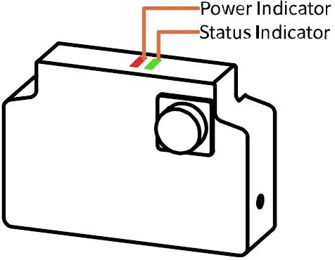
- Power indicator: it will show red light when power on.
- Status indicator: a steady green light indicates normal status; a flashing green light indicates there is an error.
IO Control
Linear Motor has three IOs, one Input and two Outputs.
- SCI1: Emergency stop of Linear Motor, low level effective.
- SCO0: Output high level, indicating there is an error of Linear Motor.
- SCO1: Output high level, indicating the position has been reached.
Linear Motor Alarm Code
Software Error Handling:
1. If there is a software error, please refer to Error Handling Method.
2. If it does not work, please re-power on the Linear Motor. Press down the Emergency stop button on the AC Control Box Pro, release it after 5 seconds, and click xArmStudio ‘initialize’ button to enable and initialize the Linear Motor.
If the problem remains unsolved after power on/off multiple times, please contact UFACTORY team for support.
| Software Error Code | Error Handling |
| T9 | Linear Motor Current Detection Error Please restart the Controller. If multiple reboots are not working, please contact technical support. |
| T11 | Linear Motor Current Over limit Please click “Clear Error” clear the Linear Motor error. |
| T12 | Linear Motor Speed Over limit Please click “Clear Error” clear the Linear Motor error. |
| T13 | Linear Motor Large Motor Position Deviation Please check if the movement of the Linear Motor is blocked, if not, please click “Clear Error” clear the Linear Motor error. |
| T14 | Linear Motor Position Command Over limit Please click “Clear Error” clear the Linear Motor error. |
| T15 | Linear Motor EEPROM Read and Write Error Please click “Clear Error” clear the Linear Motor error. |
| T20 | Linear Motor Driver IC Hardware Error Please click “Clear Error” clear the Linear Motor error. |
| T21 | Linear Motor Driver IC Initialization Error Please click “Clear Error” clear the Linear Motor error. |
| T25 | Linear Motor Command Over Software Limit Please check if the Linear Motor command is set beyond the software limit. |
| T26 | Linear Motor Feedback Position Software Limit Please contact technical support. |
| T33 | Linear Motor Drive Overloaded Please contact technical support. |
| T34 | Linear Motor Motor Overload Please contact technical support. |
| T36 | Linear Motor Driver Type Error Please click “Clear Error” clear the Linear Motor error. |
| For alarm codes that are not listed in the above table: Please click “Clear Error” clear the Linear Motor error.If it reports the same error repeatedly, please contact technical support. | |
Appendix:
xArm-Python-SDK alarm processing method:
When designing the Linear Motor path with the Python library, if the errors appear, you need to manually clear the errors. After clearing the error, re-enable the Linear Motor.
- error clearing: clean_linear_track_error()
- initialize and enable Linear Motor if necessary:
set_linera_track_enable()
set_linear_track_back_origin()
Linear Motor Technical Specifications
| UFactory Linear Motor | |
| Continue | 62N |
| Peak force | 160N |
| Maximum speed | 1000mm/s |
| Travel distance | AL1300:0-700mm; AL1301:0-1000mm |
| Maximum load mass | 200kg |
| Communication Mode | RS-485 |
| Communication Protocol | Modbus RTU |
| Programmable Gripping Specification | Position, Speed |
| Feedback | Position |
| Dimensions(L*W*H) | AL1300: 1096*214*115mm AL1301: 1382*214*115mm |
| Weight | AL1300:20kg;AL1301:24kg |
After-sales Service
- After-sales policy:
For the detailed after-sales policy of the product, see the official website: https://store-ufactory-cc.myshopify.com/pages/warranty-returns
- The general process of after-sales service is:
- Contact UFACTORY technical support ([email protected]) to confirm whether the product needs to repair and which part should be sent back to UFACTORY.
- After the bill of lading on UPS/DHL, we will send the invoice and label to you by mail. You need to make an appointment with the local UPS/DHL and then send the product to us.
- UFACTORY will check the product warranty status according to the after-sales policy.
- Generally, the process takes around 1-2 weeks except for shipment.
Note:
- Please keep the original packaging materials of the product. When you need to send the product back to get repaired, please pack the product with the original box to protect the product during the transportation.
Appendix
Appendix1 – Use Modbus-RTU communication Protocol to Control Linear Motor
Modbus RTU Communication Format
The Linear Motor defaults to the standard Modbus RTU protocol at a default baud rate is 2Mbps and the slave ID is 0x01. The currently supported function codes are: 0x03 / 0x06/ 0x10. Commonly used address for Linear Motor are: 0x0100, 0x0700, 0x0303, 0x0A0A, 0x0404, 0x004F. If need to store EEPROM, perform an ‘|’ operation with the communication address and 0x1000. For example, write servo operation mode to EEPROM, the communication address(0x0A0B) should be changed to 0x1A0B.
Note: Linear Motor needs to be initialized after each powered on.
Read Linear Motor Register
| Read Register | |||
| Request | |||
| Modbus RTU Data | Slave ID (Linear Motor) | 1 Byte | 0x01 |
| Function Code | 1 Byte | 0x03 | |
| Register Starting Address | 2 Bytes | Address | |
| Quantity of Register | 2 Bytes | N* | |
| Modbus CRC16 | 2 Bytes | CRC* | |
| Response | |||
| Modbus RTU Data | Slave ID | 1 Byte | 0x01 |
| Function Code | 1 Byte | 0x03 | |
| Byte Count | 1 Byte | N*x2 | |
| Registers Value | N*x2 Bytes | Value | |
| Modbus CRC16 | 2 Bytes | CRC* | |
N* = Quantity of Registers
Address = Register Starting Address
CRC* = Cyclic Redundancy Check
| Resgister Starting Address | Registers Value | ||
| Get Linear Motor status Register | 0x0000 | 2 Bytes | End status: 0x0000 Motion status: 0x0001 Stop status: 0x0002 |
| Get Linear Motor position Register | 0x0702 | 4bytes | 0xFFFFFFFB-0x00000320 |
| Get Linear Motor Error Register | 0x000F | 2 Bytes | An error occurs: all other return values indicate an error(except 0) No error occurred: 0x0000 |
Write Linear Motor Register
| Write Register | |||
| Request | |||
| Modbus RTU Data | Slave ID (Linear Motor) | 1 Byte | 0x01 |
| Function Code | 1 Byte | 0x10 | |
| Register Starting Address | 2 Bytes | Address | |
| Quantity of Register | 2 Bytes | N* | |
| Byte Count | 1 Byte | N*x2 | |
| Registers Value | N*x2 Bytes | Value | |
| Modbus CRC16 | 2 Bytes | CRC* | |
| Response | |||
| Modbus RTU Data | Slave ID | 1 Byte | 0x01 |
| Function Code | 1 Byte | 0x10 | |
| Register Starting Address | 2 Bytes | Address | |
| Quantity of Registers | 2 Bytes | N* | |
| Modbus CRC16 | 2 Bytes | CRC* | |
N* = Quantity of Registers
Address = Register Starting Address
CRC* = Cyclic Redundancy Check
Modbus RTU Example
- Enable Linear Motor
Enable Linear Motor Request Modbus RTU Data
Slave ID (Linear Motor) 1 Byte 0x01 Function Code 1 Byte 0x10 Register Starting Address 2 Bytes 0x01,0x00 Quantity of Registers 2 Bytes 0x00,0x01 Byte Count 1 Byte 0x02 Registers Value 2 Bytes 0x00,0x01 Modbus CRC16 2 Bytes 0x1D,0x00 Response Modbus RTU Data
Slave ID 1 Byte 0x01 Function Code 1 Byte 0x10 Register Starting Address 2 Bytes 0x01,0x00 Quantity of Registers 2 Bytes 0x00,0x01 Modbus CRC16 2 Bytes 0x00,0xAC - Set Linear Motor position
Set Linear Motor position Request Modbus RTU Data Slave ID (Linear Motor) 1 Byte 0x01 Function Code 1 Byte 0x10 Register Starting Address 2 Bytes 0x07,0x00 Quantity of Registers 2 Bytes 0x00,0x02 Byte Count 1 Byte 0x04 Registers Value 4Bytes 0x00,0x1E,0x84,0x80 Modbus CRC16 2 Bytes 0x7B,0x62 Response Modbus RTU Data Slave ID 1 Byte 0x01 Function Code 1 Byte 0x10 Register Starting Address 2 Bytes 0x07,0x00 Quantity of Registers 2 Bytes 0x00,0x02 Modbus CRC16 2 Bytes 0x40,0x25 - Set Linear Motor Speed
Set Linear Motor Speed Request Modbus RTU Data
Slave ID (Linear Motor) 1 Byte 0x01 Function Code 1 Byte 0x10 Register Starting Address 2 Bytes 0x03,0x03 Quantity of Registers 2 Bytes 0x00,0x01 Byte Count 1 Byte 0x02 Registers 2 Bytes 0x17,0x70 Modbus CRC16 2 Bytes 0xFD,0xFA Response Modbus RTU Data Slave ID 1 Byte 0x01 Function Code 1 Byte 0x10 Register Starting Address 2 Bytes 0x03,0x03 Quantity of Registers 2 Bytes 0x00,0x01 Modbus CRC16 2 Bytes 0xF1,0x14 - Set Linear Motor to Zero position
Set Linear Motor to zero position Request Modbus RTU Data
Slave ID (Linear Motor) 1 Byte 0x01 Function Code 1 Byte 0x06 Register Starting Address 2 Bytes 0x0A,0x0A Quantity of Registers 2 Bytes 0x00,0x01 Modbus CRC16 2 Bytes 0xFD,0xFA Response Modbus RTU Data
Slave ID 1 Byte 0x01 Function Code 1 Byte 0x10 Register Starting Address 2 Bytes 0x0A,0x0A Quantity of Registers 2 Bytes 0x00,0x01 Modbus CRC16 2 Bytes 0xFD,0xFA - Set Linear Motor speed to Zero position
Set Linear Motor speed to zero position Request Modbus RTU Data
Slave ID (Linear Motor) 1 Byte 0x01 Function Code 1 Byte 0x10 Register Starting Address 2 Bytes 0x04,0x04 Quantity of Registers 2 Bytes 0x00,0x01 Byte Count 1 Byte 0x02 Registers 2 Bytes 0x0B,0xB8 Modbus CRC16 2 Bytes 0xFD,0xFA Response Modbus RTU Data Slave ID 1 Byte 0x01 Function Code 1 Byte 0x10 Register Starting Address 2 Bytes 0x04,0x04 Quantity of Registers 2 Bytes 0x00,0x01 Modbus CRC16 2 Bytes 0xF1,0x14 - Get if Linear Motor is back to zero
Get if Linear Motor is back to zero Request Modbus RTU Data
Slave ID (Linear Motor) 1 Byte 0x01 Function Code 1 Byte 0x03 Register Starting Address 2 Bytes 0x0A,0x25 Quantity of Registers 2 Bytes 0x00,0x01 Modbus CRC16 2 Bytes 0xB5,0xDD Response Modbus RTU Data
Slave ID 1 Byte 0x01 Function Code 1 Byte 0x03 Byte Count 1 Byte 0x02 Registers Value 2 Bytes 0x00,0x01 Modbus CRC16 2 Bytes 0x79,0x84 - Monitor the distance between the photoelectric sensor and the fisrt Z phase
Monitor the distance Request Modbus RTU Data
Slave ID (Linear Motor) 1 Byte 0x01 Function Code 1 Byte 0x03 Register Starting Address 2 Bytes 0x0A,0x28 Quantity of Registers 2 Bytes 0x00,0x01 Modbus CRC16 2 Bytes 0xE4,0x1D Response Modbus RTU Data Slave ID 1 Byte 0x01 Function Code 1 Byte 0x03 Byte Count 1 Byte 0x02 Registers Value 2 Bytes 0x06,0xF2 Modbus CRC16 2 Bytes 0x3A,0x61 - Locating end range
Locating end range Request Modbus RTU Data Slave ID (Linear Motor) 1 Byte 0x01 Function Code 1 Byte 0x10 Register Starting Address 2 Bytes 0x0A,0x0B Quantity of Registers 2 Bytes 0x00,0x01 Byte Count 1 Byte 0x02 Registers Value(1000) 2 Bytes 0x03,0xE8 Modbus CRC16 2 Bytes 0x0C,0xC0 Response Modbus RTU Data
Slave ID 1 Byte 0x01 Function Code 1 Byte 0x10 Register Starting Address 2 Bytes 0x0A,0x0B Quantity of Registers 2 Bytes 0x00,0x01 Modbus CRC16 2 Bytes 0x73,0xD3 - Soft emergency stop
trigger soft emergency stop Request Modbus RTU Data Slave ID (Linear Motor) 1 Byte 0x01 Function Code 1 Byte 0x10 Register Starting Address 2 Bytes 0x0A,0x0B Quantity of Registers 2 Bytes 0x00,0x01 Byte Count 1 Byte 0x02 Registers Value(1000) 2 Bytes 0x00,0x01 Modbus CRC16 2 Bytes 0xCC,0xBE Response Modbus RTU Data Slave ID 1 Byte 0x01 Function Code 1 Byte 0x10 Register Starting Address 2 Bytes 0x0A,0x0E Quantity of Registers 2 Bytes 0x00,0x01 Modbus CRC16 2 Bytes 0x63,0xD2 - get Linear Motor SN
get Linear Motor SN Request Modbus RTU Data
Slave ID (Linear Motor) 1 Byte 0x01 Function Code 1 Byte 0x03 Register Starting Address 2 Bytes 0x0B,0x10 Quantity of Registers 2 Bytes 0x00,0x02 Modbus CRC16 2 Bytes 0xB5,0xDD Response Modbus RTU Data Slave ID 1 Byte 0x01 Function Code 1 Byte 0x03 Byte Count 1 Byte 0x04 Registers Value 2 Bytes ** Modbus CRC16 2 Bytes ** - get input SCI status
get input SCI status Request Modbus RTU Data
Slave ID (Linear Motor) 1 Byte 0x01 Function Code 1 Byte 0x03 Register Starting Address 2 Bytes 0x0A,0x26 Quantity of Registers 2 Bytes 0x00,0x01 Modbus CRC16 2 Bytes 0x86,0x17 Response Modbus RTU Data Slave ID 1 Byte 0x01 Function Code 1 Byte 0x03 Byte Count 1 Byte 0x02 Registers Value 2 Bytes ** Modbus CRC16 2 Bytes ** - get output SCO status
get output SCO status Request Modbus RTU Data
Slave ID (Linear Motor) 1 Byte 0x01 Function Code 1 Byte 0x03 Register Starting Address 2 Bytes 0x0A,0x27 Quantity of Registers 2 Bytes 0x00,0x01 Modbus CRC16 2 Bytes 0xD7,0xD7 Response Modbus RTU Data
Slave ID 1 Byte 0x01 Function Code 1 Byte 0x03 Byte Count 1 Byte 0x02 Registers Value 2 Bytes ** Modbus CRC16 2 Bytes **
get status area
address start from 0x0A20
| get status area | |||
| Request | |||
| Modbus RTU Data | Slave ID (Linear Motor) | 1 Byte | 0x01 |
| Function Code | 1 Byte | 0x03 | |
| Register Starting Address | 2 Bytes | 0x0A,0x20 | |
| Quantity of Registers | 2 Bytes | 0x00,0x08 | |
| Modbus CRC16 | 2 Bytes | 0x46,0x1E | |
| Response | |||
Modbus RTU Data | Slave ID | 1 Byte | 0x01 |
| Function Code | 1 Byte | 0x03 | |
| Byte Count | 1 Byte | 0x10 | |
| Registers Value | 16 Bytes | ** | |
| Modbus CRC16 | 2 Bytes | ** | |
Registers Value – 16 Bytes: 00 00 0F A0 00 00 00 00 00 01 00 01 00 02 00 02
- 1-4 bytes: 00 00 0F A0 , current position(unit: number of pulses)
- 5-6 bytes: 00 00, get Linear Motor status(same as address 0x0000)
- 7-8 bytes: 00 00, error code
- 9-10 bytes: 00 01, enable status
- 11- 12 bytes: 00 01, if get back to zero
- 12- 14 bytes: 00 02, SCI status
- 15-16 bytes: 00 02, SCO status


