![]()
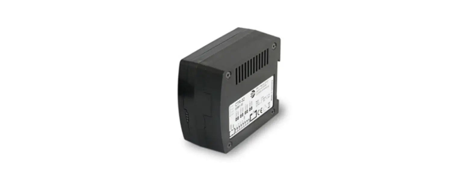
MBJ CTR-52 Controller
Safety Notes
- The device is designed for indoor use only.
- Health The device must be disconnected from the power source before the installation and/or maintenance can start. The device must not be used when a failure may cause personal injury.
- Electricity The housing is electrically isolated from the ground of the power supply. Exceeding the permissible operating voltage or exceeding the maximum allowed switching current per channel can lead to the destruction of the device or to a significant shortening of the lifetime of the connected LED lighting module.
- Mechanical integration The controller is made for top hat rail mounting. A clip can be used to lock the unit to the top hat rail. For optimal heat flow a left/right distance of 10mm to next unit is recommended.
Mechanical Integration
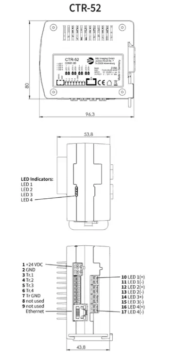
Status LED’s CTR-52
| LED | Status | Meaning |
| LED 1 | OFF ON | Trigger low state Trigger high state |
| LED 2 | OFF ON | Trigger low state Trigger high state |
| LED 3 | OFF ON | Trigger low state Trigger high state |
| LED 4 | OFF ON | Trigger low state Trigger high state |
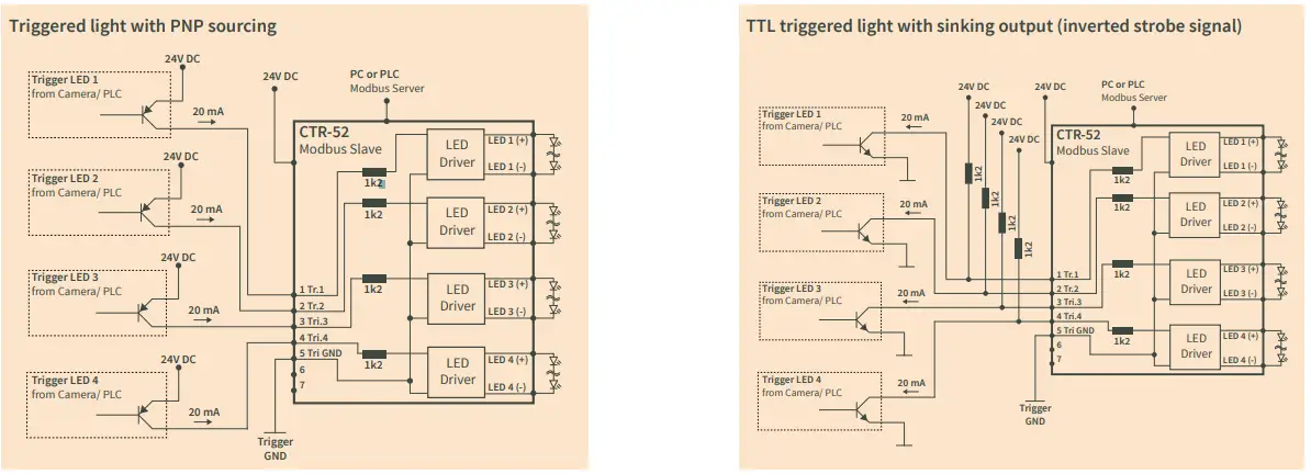
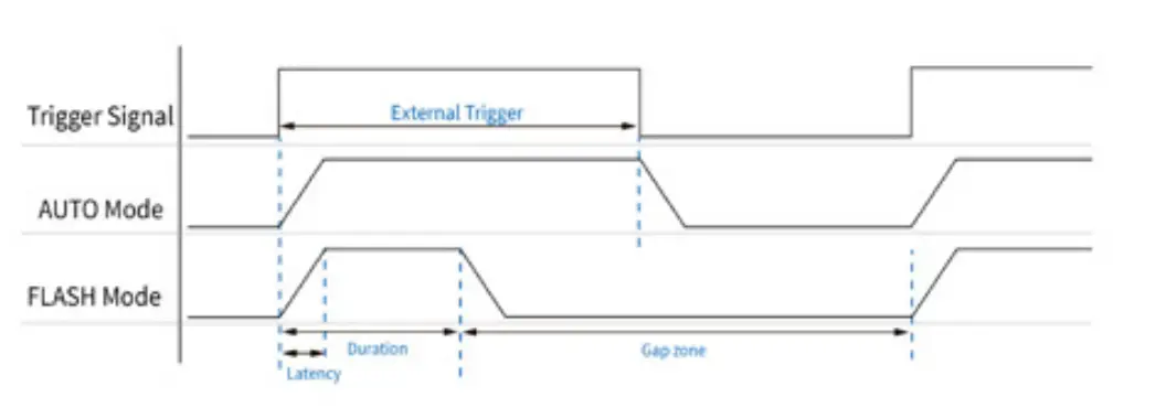
Trigger Signals
CTR-52
- 4 channel LED driver
- Current controlled operation for continuous and brightness controlled LED light
- Voltage controlled operation for short, precise and high-power LED flashes, precise
- flash pulses from 10µs to 100ms
- Full control via Modbus TCP/IP
- MS Windows 10® based control software and SDK available
- Straight flash control via the camera’s ‘exposure time’,
- the ‘strobe‘ signal or manual flash set-up
- 4 individual trigger I/O lines with flexible assignment to the LED channels
- Passive cooling and overheat protection
Electrical Connections
| Pin | Pin Name | CTR-52 Function | Comment |
| 1 | 24VDC | 24V DC | Power supply input |
| 2 | GND | Ground | Power supply ground |
| Pin Name | Function | Comment | |
| 3 | Tr.1 | Trigger1 12-24V 1) | Internally opto-coupled |
| 4 | Tr.2 | Trigger2 12-24V | Internally opto-coupled |
| 5 | Tr.3 | Trigger3 12-24V | Internally opto-coupled |
| 6 | Tr.4 | Trigger4 12-24V | Internally opto-coupled |
| 7 | Tr. GND | Trigger ground | Common Tr. ground, isolated |
| 8 | — | not used | |
| 9 | — | not used | |
| Pin Name | Wire2) | Output to light | |
| 10 | LED1+ | black + blue | Channel 1 |
| 11 | LED1-3) | white + brown | Channel 1 |
| 12 | LED2+ | black + blue | Channel 2 |
| 13 | LED2-3) | white + brown | Channel 2 |
| 14 | LED3+ | black + blue | Channel 3 |
| 15 | LED3-3) | white + brown | Channel 3 |
| 16 | LED4+ | black + blue | Channel 4 |
| 17 | LED4-3) | white + brown | Channel 4 |
| Port | Function | Comment | |
| Eth | RJ45 network | Modbus over Ethernet |
- Signal high >=10V, signal low <=5V
- For MBJ connecting cable and MBJ LED light (-x) without integrated controller
- Do NOT connect LED(-)to the external ground of the power supply or the ground of the trigger signal! This might destroy connected lights or devices
Operating Mode
The CTR-52 factory setting of the operation mode is FLASH. Other operating modes are selectable via the Modbus interface
| Mode | CTR-52 Function |
| STEADY | Continuous light, LED always on |
| AUTO | LED output follows the trigger status |
| FLASH1) | Manual set-up for flash, delay and duration via Modbus protocol |
| OFF | LED output is switched off |
Modbus Control
Hardware
The standard fieldbus provided with the CTR LED controller product line is based on Modbus TCP. Modbus is a data communications protocol for use with programmable logic controllers (PLCs).
Modbus Setup Information
The CTR controller is a Modbus device that allows you to access the light settings via Ethernet. The controller communicates using a master-slave technique in which only one device (the master) can initiate transactions (called queries). The other devices (slaves) respond by supplying the requested data to the master, or by taking the action requested in the query. The CTR light controller is implemented as a Modbus slave. The CTR receives messages from the master, processes them and responds to them. The product does not send messages by itself
| Modbus Setup Information | |
| Modbus Type: | Slave (Server) |
| Modbus Format: | Modbus TCP |
| Output Data Mode: | Auto |
Notes
- The default device IP address is 192.168.0.99. The address can be changed via the command line tool provided with the MBJ software package
- The RESET Button on the back of the device can be used to return to the factory default settings
- Please refer to the fieldbus communication protocol definition for details Software
- The CTR-52 can be programmed via different alternative methods:
- Direct Modbus access for which a detailed protocol definition is provided
- SDK library to integrate the communication into your software
- The easy to use MBJ software user interface based on MS Windows 10®
- For further information and download of the CTR-52 software components visit: www.mbj-imaging.com/en/products/led-controller
Specification
- LED current less than 100mA may cause LED light jitter
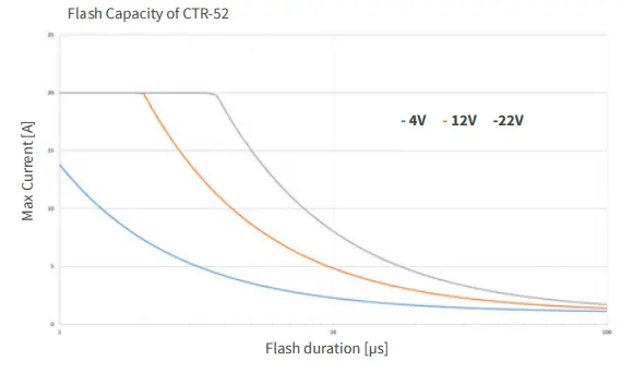
- The flash energy is provided by a capacitor and requires sufficient time for recharging. The flash energy (flash frequency * flash duration * current) is limited to 1A. E.g.: 100 flashes/s * 100µs * 30A = 0.3A
- The higher the current and the shorter the cycle time, the greater the latency can be
Specification CTR-52 Electrical parameter Operating Voltage 24V DC / 4A 12V – 26V, min. 2V above the forward voltage of the LED light source
LED steady current1) (ON & AUTO mode)
1 Channel: 1800mA 2 Channels: 1500mA p. Channel 3 Channels: 1200mA p. Channel 4 Channels: 900mA p. Channel
LED flash current2) 100mA…21A Min flash duration 10µs depending on LED working point and duty cycle
Max. flash duration 59s Max. flash latency3) 3µs Flash duration & delay: smallest adjustable step
1µs Voltage range for LED modules approx. 2.5V to 22V Mechanical parameter Dimension (H x W x D) 53mm x 80mm x 93mm Weight 220g Connectors 1x 2 Pin plug contact (RM5.08), 1x 7 Pin plug contact (RM3.81), 4x 2 Pin inv. plug contact (RM3.81)
1x RJ45 Ethernet
Certifications CE, RoHS Degree of protection IP20 (made for control cabinet) Humidity 30% to 70% Operating temperature 10°C to 30°C Accessories Top rail mounting clip and plugs (scope of de- livery). For cable, mounts and lighting modules please check www.mbj-imaging.com
Application Samples for CTR-52 Controller