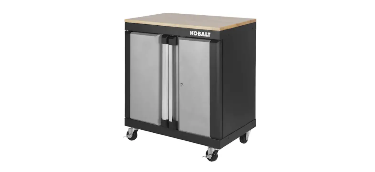
KOBALT 0019002 28-in 2 Door Base Cabinet Instruction Manual
PRODUCT SPECIFICATION
CMPONENTS | SPECIFICATION |
Maximum load for wood top | 100 lbs. |
| Maximum load for bottom shelf | 100 lbs. |
Maximum load for adjustable shelf | 100 lbs. |
| Maximum total load | 300 lbs. |
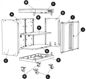
PACKAGE CONTENTS
| PARTS | DESCRIPTION | QUANTATY |
A | Left back panel | 1 |
| B | Right back panel | 1 |
C | Left side panel | 1 |
| D | Right side panel | 1 |
E | Base panel | 1 |
F | Top panel | 1 |
| G | Bottom shelf | 1 |
H | Adjustable | 1 |
I | Left door | 1 |
| J | Right door | 1 |
K | Fixed caster | 2 |
| L | Swivel caster with brake | 2 |
M | Wood top | 1 |
HARDWARE CONTENTS (shown actual size)
- ST4.8 x 10 mm Screw Qty. 12 + 2

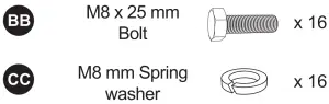
- M8 x 25 mm Bolt Qty. 16 + 2

- M8 mm Spring washer Qty. 16 + 2

- M8 mm Falt washer Qty. 16 + 2

- Lock (Preassembled to right door(J)) Qty. 1

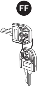
- Key (Preassembled to locking bar of right door(J)) Qty. 2


SAFETY INFORMATION
Please read and understand this entire manual before attempting to assemble or operate this product. Failure to follow may result in serious injury. Save all warnings and instructions for future reference.
![]() WARNING
WARNING
- Do not stand on, step on, or alter this unit for anything outside the designed function of storage.
- Use care when handling and assembling metal plates. Lock wheels when the product is not being moved.
- The metal may have sharp edges or corners. The use of protective gloves is recommended.
- Close and lock the doors before moving this product.
- Always remember to use proper lifting techniques when moving the boxed or assembled unit.
CAUTION
- Do not exceed maximum load capacities listed in Product Specifications.
- When storing articles, equally distribute loads. Always balance the loads to avoid tipping.
- Place more than half the total load weight on the bottom cabinet when possible.
- Keep the product on level surfaces. The product may become unstable and it may tip over if stored or moved on an uneven surface, which may cause personal injury or product damage.
- Do not store flammable liquids in the unit unless they are secured in an approved container.
- Do not store gasoline in the unit under any circumstances.
- Do not leave children unattended near this product. Cabinet may tip over if improperly opened.
- Always use common sense and be cautious when using this product.
PREPARATION
Before beginning assembly of product, make sure all parts are present. Compare parts with package contents list and hardware contents above. If any part is missing or damaged, do not attempt to assemble the product. Contact customer service for replacement parts.
It is recommended that this product to be assembled on a clean, soft surface, such as a piece of cardboard.
Estimated Assembly Time: 30 minutes (does not include unpacking time)
Tools Required for Assembly (included): 14 mm Wrench
Tools Required for Assembly (not included): Drill, PH2 screwdriver, Rubber mallet.
ASSEMBLY INSTRUCTIONS
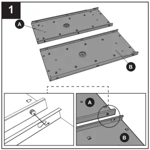
- Slide preassembled screws in left back panel (A) into key slots of right back panel (B) to connect the two back panels together. Tighten the screws.
Note: Be sure to keep the back panels on a soft surface, such as carpeting or a piece of cardboard, to protect them from scratches.
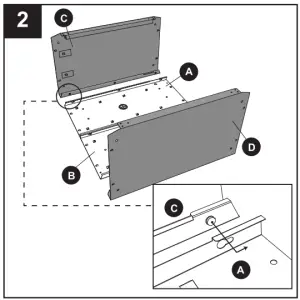
- Slide preassembled screws into key slots of the assembled unit from Step 1 to connect left side panel (C) and right side panel (D) to the assembled unit. Tighten the screws.
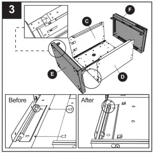
- Align the base panel (E) with the assembled unit from Step 2 carefully. Tap the base panel (E) into the unit until the clips are secured tightly. Repeat this step to attach the top panel (F) to the assembled unit.
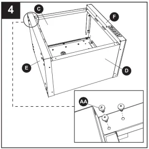
Note: Recommended to use a rubber mallet to tap the components together. - Check and verify the holes in front edge of base panel (E) and top panel (F) are aligned with the holes in left side panel(C) and right side panel (D). If not, check and make sure the base panel (E) and top panel (F) are located at the right place. Tighten the ST4.8 x 10 mm screws (AA) to the holes to make the unit securely fixed.
Hardware Used
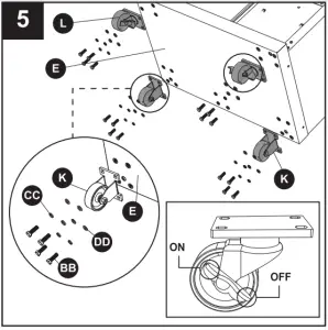
- Mount the two fixed casters (K) to the base panel (E) using M8 x 25 mm bolts (BB), M8 mm spring washers (CC) and M8 mm falt washers (DD). Repeat this process for the swivel casters with brake (L) on the opposite side of the base panel (E). Lock the swivel casters with brake (L) before you proceed to the step 6. Place the cabinet upright.
Note: The swivel casters with brake (L) must be installed in the front of the cabinet. Be sure to lock both casters to prevent cabinet from rolling or swiveling. Do not over tighten the screws.
Hardware Used


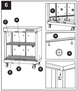
- Install the bottom shelf (G) by tipping it to the side and inserting it into the cabinet. With bottom shelf (G) at an angle, align the cut-outs on the bottom shelf (G) with the back seams caused by side panels (C and D) and back panels (A and B). Carefully lower the bottom shelf (G), ensuring the front of the bottom shelf (G) ° goes over the front flange of the base panel (E).
Determine the location for the adjustable shelf (H). Hold the adjustable shelf (H) at an angle to make it easier to install. Please make sure adjustable shelf (H) snaps into the hooks on the unit.
Note: If the hooks are flatted during assembly, use a slotted screwdriver (not included) to recover them.
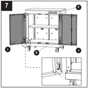
- Lift and pull the L-shaped pivot pin on the edge of the left door (I), aligning the assembling holes of the base panel (E) and top panel (F), then release. Repeat for right door (J).


TROUBLESHOOTING
PROBLEM | POSSIBLE CAUSE | CORRECTIVE ACTION |
Screw(s) will not align into hole(s). |
|
|
LIFETIME HASSLE-FREE GUARANTEE
This product carries a lifetime warranty. If the product is found to be defective, please call 1-888-3KOBALT, 8 a.m. – 8 p.m., EST, Monday – Sunday, or return the tem to the place of purchase with a copy of the original sales receipt. The distributor will, at its option, repair or replace the product.
This warranty gives you specific legal rights, and you may have other rights that vary from state to state.
REPLACEMENT PARTS LIST
For replacement parts, call our customer service at 1-888-3KOBALT, 8 a.m. – 8 p.m., EST, Monday – Sunday.
PARTS | DESCRIPTION | PARTS# |
| A | Left back panel | 2368779-A |
| B | Right back panel | 2368779-B |
| C | Left side panel | 2368779-C |
| D | Right side panel | 2368779-D |
| E | Base panel | 2368779-E |
| F | Top panel | 2368779-F |
| G | Bottom shelf | 2368779-G |
| H | Adjustable shelf | 2368779-H |
| I | Left door | 2368779-1 |
| J | Right door | 2368779-J |
| K | Fixed caster | 106453-FC |
| L | Swivel caster with brake | 106453-SC |
| M | Wood top | 2368779-M |
| R | Door magnet | 106453-R |
| S | Door L shape pivot pin & spring | 106453-PS |
| T | Rubber grommet | 106453-RG |
| AA | ST4.8 x 10 mm Screw | 2368779-HDWR |
| BB | M8 x 25 mm Bolt | 2368779-HDWR |
| CC | M8 mm Spring washer | 2368779-HDWR |
| DD | M8 mm Falt washer | 2368779-HDWR |
| EE | Lock | 106453 LK |
| FF | Key | 106453-LK |
![]() Questions, problems, missing parts† Before returning to your retailer, call our 0 customer service department at 1-888-3KOBALT (1-888-356-2258), 8 a.m. – 8 p.m., EST, Monday – Sunday.
Questions, problems, missing parts† Before returning to your retailer, call our 0 customer service department at 1-888-3KOBALT (1-888-356-2258), 8 a.m. – 8 p.m., EST, Monday – Sunday.

SCAN ME
A STEP BY VIDEO ON HOW TO ASSEMBLY & THE TOOLS NEEDE