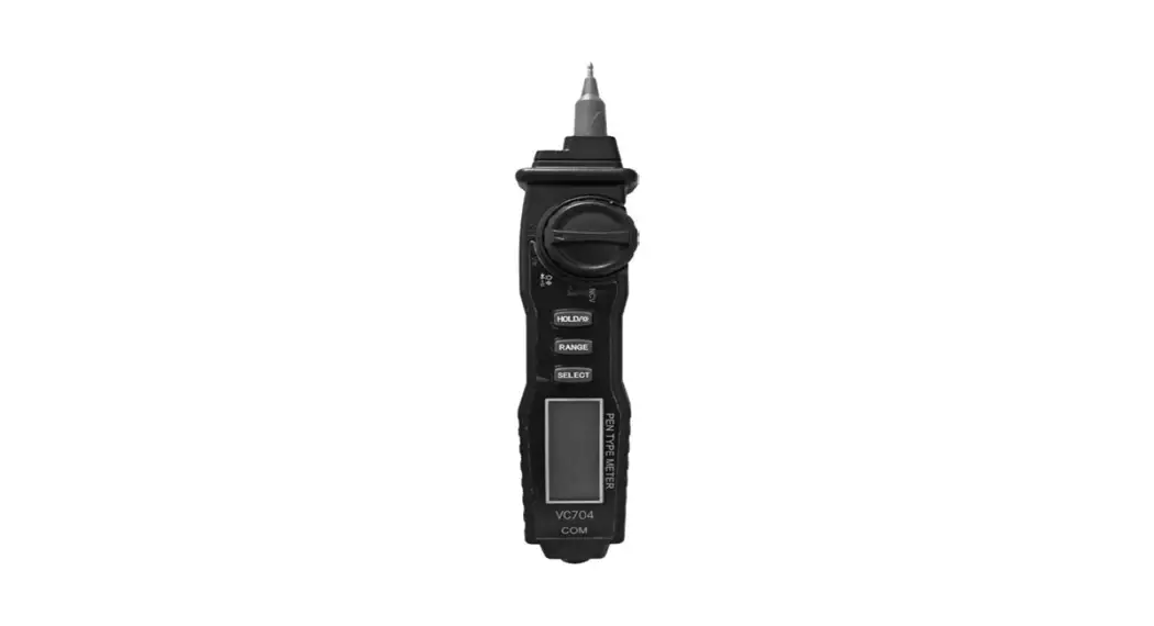
![]() VC704 Universal Multimeter
VC704 Universal Multimeter
User Manual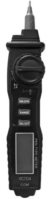 Universal multimeter
VC704
VC704 Universal Multimeter
General information
Universal multimeter with automatic selection of the measuring range and non-contact voltage detector (NCV)
- Measurements: AC/DC amperage and voltage, resistance, capacitors
- diode test
- circuit continuity test
- LCD display (3.5 digits)
- backlight
- low battery indicator
- overload protection
- power supply: 2 x AAA.
Safety guidelines
- Prior to initiation of device’s usage it is recommended to get thoroughly acquainted with operating manual and terms of safe use. This will allow avoiding an electric shock, health damages or loss of life, as well as it may prevent damages to the device.
- Prior to commencing measurements it is recommended to check for damages on device’s casing or measuring cables. In case any cable or device damages are detected device should not be used, as it may pose an electric shock threat.
- The device should not be used when insulation wrapping the probes and cables is damaged.
- Only gauging cables delivered with the set may be used for measurements. In case gauging cables are damaged they should be replaced with cables of exact technical parameters.
- The device can be used only for measurements compliant with the manual and its technical specification. Otherwise, device’s safety provisions may not be sufficient for safe usage.
- During measurements all metal ends and gauging slots should not be touched. Fingers should be kept above insulation sheaths.
- It is not allowed to make measurements with wet hands or in places with excessive air humidity.
- It is not recommended to exceed upper limits of electric values given for each gauging range. When the scale of measured electric value is not known selection of the highest range is recommended for gauging.
- It is not recommended to place any electronic elements into gauging slots during voltage measurements with gauging probes.
- Prior to transistor test you should make sure that gauging probes have been disconnected from another gauged circuit.
- Prior to measurement of resistance,circuit continuity and capacitor’s capacity the capacitances should be discharged and all power supply sources disconnected.
- Particular caution should be taken by measurements, which exceed DC 60 V or AC 30 V rms.
- Prior to commencement of measurement the function range switch should be set in an adequate position. Shifting switch during the measurement may cause damage to the device.
- Gauging probes should be removed from gauging slots prior to every change of measured parameters.
- The device should not be used, or kept, in high air humidity or temperature conditions, in strong electromagnetic field or in an explosive or flammable environment. Such conditions may influence gauging results and create an electric shock hazard.
- The device should not be used when the display indicates exhausted battery. Low battery level may lead to faulty gauging indications.
- Make sure that the device is switched off before batteries are replaced.
- In case device is not used for a longer period of time the battery should be removed in order to avoid spilling of electrolyte.
- Device should be used and stored in a place inaccessible for children.
- Device is designed to be used indoors, in room temperature.
- Device should not be used directly after it is relocated from a room with high air humidity, excessively low or high temperature conditions.
Technical specification
Measurement accuracy for particular gauging values is given for 1 year from calibration date and for an operating temperature of 23ºC
5ºC and air humidity of 75%. Accuracy:
% of indicated value
number of least significant digits. 3.5 digit LCD display
power supply: 2 x AAA
number of readouts: 2 / s
dimensions: 205 x 43 x 32 mm
operating conditions: od 0-40ºC, humidity < 75%
storage conditions: od –10ºC to +50ºC, humidity < 75%
weight: ok. 80g
Safety category
CAT I – gauging category CAT I defines safety requirements for measurements in devices which are not connected directly to a low voltage network, such as batteries, accumulators, flashlights.
CAT II – gauging category CAT II defines safety requirements for measurements carried out in devices directly connected to a low voltage network, such as home appliances, office equipment or workshop equipment.
CAT III – gauging category CAT III defines safety requirements for measurements carried out in the circuits of installations inside buildings.![]() Multimeter should not be used for measurements of devices defined by CAT IV.
Multimeter should not be used for measurements of devices defined by CAT IV.
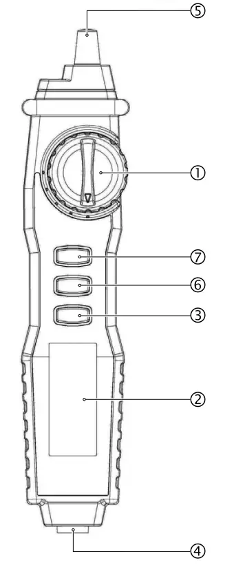
Description
- FUNCTION RANGE SWITCH
- LCD display
- SELECT – selection of measurement functions
- COM: gauging socket, to be connected with the black “-” cable
- TEST PEN „+”
- RANGE – manual or automatic selection of the measuring range
- HOLD – function remembering the last measurement (HOLD) / display backlight
AC/DC voltage measurement
- Set range switch 1 to position V
 /~.
/~. - Press SELECT button 3 and choose ACV or DCV function.
- Connect the black testing cable to COM socket 4.
- Connect the measuring tip 5 to measured circuit or device.
- Read voltage and polarity value on the display 2.
| AC/DC range | Resolution | Accuracy | Input impedance |
| DC 400 mV | 100 pV | ±0.8%+5 digits | 10 MS? |
| DC 4 V | 1 mV | ±0.8%+3 digits | |
| DC 40 V | 10 mV | ||
| DC 400 V | 100 mV | ||
| DC 600 V | 1V | ±1.0%+3 digits | |
| AC 4 V | 1 mV | ±1.0%+3 digits | |
| AC 40 V | 10 mV | ||
| AC 400 V | 100 mV | ||
| AC 600 V | 1V | ±1.2%+5 digits |
Frequency: 40–400 Hz![]() Never perform the measurement of current if open circuit voltage to earth exceeds DC 600 V.
Never perform the measurement of current if open circuit voltage to earth exceeds DC 600 V.
AC/DC amperage measurement
- Connect the black testing cable to COM socket 4.
- Set range switch 1 to position mA.
- Press SELECT button 3and choose ACA or DCA function.
- Connect the measuring tip 5to measured circuit or device.
- Read amperange and polarity value on the display 2.
| AC/DC range | Resolution | Accuracy | |
| DC 40 mA | 10 µA | ±1.0%+3 digits | voltage drop 200 mV |
| DC 200 mA | 100 µA | ||
| AC 200 mA | 10 µA | ±1.2%+5 digits | |
| AC 40 mA | 100 µA |
![]() Frequency: 40–400 Hz
Frequency: 40–400 Hz
The current measurement must be run in series in the circuit, and the measuring range should not exceed 200 mA.
Resistance measurement
- Connect the black testing cable to COM socket 4 .
- Set range switch 1 to position
 .
. - Press SELECT button 3 and choose Ω .
- Connect the measuring tip 5 to measured resistor.
- Read value on the display 2 .
| RangeΩ | Resolution | Accuracy |
| 400 Ω | 0.1 Ω | ±1.0%+5 digits |
| 4 kΩ | 1 Ω | |
| 40 kΩ | 10 Ω | |
| 400 kΩ | 100 Ω | |
| 4 MΩ | 1 kΩ | |
| 40 MΩ | 10 kΩ | ±1.2%+8 digits |
![]() The test tip polarity is „+”. Before measuring resistance, turn off power to the circuit and make sure all capacitors are discharged. The 200Mm range has a constant of 10 digits (1Mm ), this value will appear in the short-circuit state, it must be subtracted from the measurement result, e.g. when measuring a 100MΩ resistor, the display will show 101.0 and the last 10 digits should be subtracted. When the input is not connected, ie with an open circuit, the digit „1” will be displayed for the condition of exceeding the range.
The test tip polarity is „+”. Before measuring resistance, turn off power to the circuit and make sure all capacitors are discharged. The 200Mm range has a constant of 10 digits (1Mm ), this value will appear in the short-circuit state, it must be subtracted from the measurement result, e.g. when measuring a 100MΩ resistor, the display will show 101.0 and the last 10 digits should be subtracted. When the input is not connected, ie with an open circuit, the digit „1” will be displayed for the condition of exceeding the range.
Capacitance measurement
- Set range switch 1 to position .
- Press SELECT button 3and choose
 .
. - Connect the black testing cable to COM socket 4 .
- Connect the measuring tip 5 to anode and the black testing cable to cathode.
- Read value on the display 2.
| Range | Resolution | Accuracy |
| 4 nF | 1 pF | ± 3.0%+5 digits |
| 40 nF | 10 pF | |
| 400 nF | 100 pF | |
| 4 µF | 1 nF | |
| 40 µF | 10 nF | |
| 400 µF | 100 nF | |
| 4 mF | 1 µF | ± 5.0%+10 digits |
![]() To avoid damaging the Meter, disconnect circuit power and discharge all high-voltage capacitors before measuring capacitance. Never apply voltage to the input terminals, otherwise serious damage may result.=
To avoid damaging the Meter, disconnect circuit power and discharge all high-voltage capacitors before measuring capacitance. Never apply voltage to the input terminals, otherwise serious damage may result.=
Circuit continuity test
- Set range switch 1 to position .
- Press SELECT button 3 and choose
 .
. - Connect the black testing cable to COM socket 4 .
- Connect the measuring tip 5 to measured circuit or device.
- The continuity of the circuit will be signaled by an acoustic signal at resistance < 30 Ω .
Diode test
- Set range switch 1 to position .
- Press SELECT button 3 and choose
 .
. - Connect the black testing cable to COM socket 4 .
- Connect the measuring tip 5 to anode and the black testing cable to cathode of the diode.
- Read value on the display 2.
Voltage detector NCV
- Set range switch 1 to position NCV.
- Bring the measuring tip closer 5 to the tested live circuit.
- When voltage is detected, acoustic signal will appear and the display will show the voltage value.
Battery replacement
Replace the battery with a new one when the low battery symbol![]() 9 appears on the LCD display. Low battery level can cause erroneous measurements.
9 appears on the LCD display. Low battery level can cause erroneous measurements.
- Remove the back cover of the multimeter.
- Place new 2 x AAA batteries, paying attention to proper polarization.
- Before removing the back cover, disconnect all test leads from the meter and the measured circuit and the switch and the meter off
- It is recommended to use batteries and fuses consistent with device’s specification
- Used batteries as hazardous waste should be disposed of in a specially marked container in or sent to a selective collection point
- Do not throw batteries into a rubbish bin
- Do not use new and used batteries at the same time.
![]() Please refer to the local collection and segregation rules for electrical and electronic equipment. Observe the regulations and do not dispose electrical and electronic equipment with cosumer waste. Proper disposal of used products helps to reduce their harmful effects on the environment and human health.
Please refer to the local collection and segregation rules for electrical and electronic equipment. Observe the regulations and do not dispose electrical and electronic equipment with cosumer waste. Proper disposal of used products helps to reduce their harmful effects on the environment and human health.
![]() Electromalt Limited
Electromalt Limited
15, Level 1, Suite 4, Naxxar Road,
Birkirkara, BKR9049
Malta
tel. 00356 77028874
www.electromalt.com
[email protected]![]()


