 Pyle PLUTV42CH Marine Grade Waketower Speakers System
PRECAUTIONS
- This unit is designed for negative ground 12-14.50 Volts (DC) operation only.
- Use speakers with an impedance of 4 Ohms
- Avoid installing the unit where:
- It would be subject to high temperatures, such as from direct sunlight or hot air from the heater.
- It would be exposed to rain or moisture.
- It would be subject to dust or dirt.
- If your vehicle or boat is parked in direct sunlight and there is a considerable rise in temperature inside the car, allow the unit to cool off before operation.
- When installing the unit horizontally, be sure not to cover the heatsink fins with the floor carpet.
- If this unit is placed too close to the resources radio, interference may occur. In this case, separate the amplifier from the car radio.
- This power amplifier employs a protection circuit to protect the transistors and speakers if the amplifier malfunctions. Do not attempt to test the protection circuits by covering the heat sink or connecting improper loads.
- Do not use the unit with a weak auto battery as its optimum performance depends on a normal battery supply voltage.
- For safety reasons, keep the volume of your audio system moderate so that you can still hear normal traffic sounds in a reasonable distance.
WIRING INSTRUCTIONS
POWER CONNECTION
The battery terminal (BATT ) must be connected directly to the positive terminal of the vehicle battery to provide an adequate voltage source and minimize noise. Connecting the battery terminal lead to any other point (such as the fuse block) will reduce the power output and may cause noise and distortion. Use only #12 gauge or thicker (smaller gauge #) wire for this lead and connect it to the terminal of the battery after all other wiring is completed.
GROUND CONNECTION
The ground terminal (GND) connection is also critical to the correct operation of the amplifier. Use a wire of the same gauge as the power connection (#8 or thicker) and connect it between the ground terminal (GND) of the amplifier and a metal part of the vehicle close to the mounting location. This wire should be as short as possible and any paint or rust at the grounding point should be scraped away to provide a clean metal surface to which the end of the ground wire can be screwed or bolted.
REMOTE TURN-ON CONNECTION
The amplifier is turned on by applying +12V to the remote turn-on terminal (REM). The wire lead to this terminal should be connected to the “Auto-Antenna” lead from the vehicle/or boat stereo resources which will provide the +12V only when the stereo resources is turned on . If the car stereo does not provide an “Auto-Antenna” lead, the remote turn-on lead may be wired to an “Accessory” or “Radio” terminal in the vehicle’s/or boat’s fuse block. This will turn the amplifier on and off with the ignition key, regardless of whether the stereo resources is on or off.
The remote turn-on lead does not carry large currents. So #16 gauge wire may be used for this application.
SPEAKER CONNECTIONS
Depending on the type and number of speakers used with the amplifier wire them to the speaker terminals as per the appropriate wiring diagram. For most applications, #18 gauge wire should be used for the speaker leads but in no case thinner than #16 gauge. For leads is an excess of 10 feet #12 gauge is recommended. When wiring the speakers, pay careful attention to the polarity of the terminals on the speakers and make certain they correspond to the polarity of the corresponding terminals on the amplifier. Do not ground any speaker leads to the chassis of the vehicle/or boat.
OPERATION
After the amplifier has been installed and all connections have been made carefully and securely, turn the radio on so that the amplifier is switched on automatically. After a short power-on period, the amplifier reaches its full performance. Now turn up the volume slowly using the volume control of the radio. If there is no sound or only a distorted replay, switch off the radio immediately – the amplifier will also switch off automatically – and check if all connections have been made correctly.
GND (-) = GROUND CONNECTION
Connect the GND terminal to the chassis ground of your vehicle/or boat and take care of the best electric and mechanic contact. In doing so, drill a hole into the vehicle/or boat chassis near the amplifier then remove color, dirt or any other substance from the ground point. Thereafter fasten the cable end with added ring terminal by using a screw. Ensure that the ground connection is as short as possible and that the cable diameter is sufficient (min 4mm). Route the ground cables from the radio and all other equipment parts, like equalizer, active crossover network or other amplifiers, to the same ground point.
+ 12V = POWER SUPPLY
Connect the BATT terminal to the positive pole of the battery with a lead cable and add a fuse into the power cable at a distance of not more than 30 cm from the battery. The lead cable’s diameter should be at least 4 mm for a length of 3 m and 6 mm for a length of 6 m.
REM (ON/OFF) REMOTE CONTROL
Connect the REM terminal to the automatic antenna connector of your vehicle/or boat radio. Now when turning on and off your vehicle/or boat radio, the amplifier automatically switches ON and OFF. A cable diameter of 0.5mm2 is sufficient.
SPEAKERS CONNECTIONS
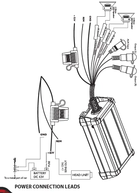
Speaker output
- +CHI White
- -CHI White + Black
- +CH2 Grey
- -CH2 Grey + Black
Level Input / Output
- IN Black (AUX)
- OUT White (L)
- OUT Red (R)
Power
- +12V Red
- GND Black
- REM Blue
NOTES ON THE POWER SUPPLY
- Connect the +12V power input lead only after all other leads have been connected.
- Be sure to connect the ground wire of the unit securely to a metal part of the vehicle/or boat.
- The loose or faulty connection may cause amplifier malfunction
- REM: The unit is turned on by applying +12 Volts to this terminal. This terminal does not draw heavy currents like the two Power Terminals so a thinner connecting wire is acceptable. Standard 18 GAUGE is fine and the standard color is red. If the radio is equipped with a Power Antenna control wire, it can drive this terminal. If the Power Antenna wire is already in use, you can still splice it into it. With this method, the unit will turn ON automatically with the radio.
- Use the power supply lead with a fuse attached whose value is the same as the original fuse.
- Place the fuse in the power supply lead as close as possible to the car battery.
- During a full-power operation, a Maximum current will run through the system. Therefore, make sure that the leads to be connected to the +12V and GND terminals of the unit respectively must be larger than 18-Gauge (AWG.18) proper Bridged operation. If only a mono signal is available, a “Y” adapter is required.
FUSE REPLACEMENT
If the fuse blows, check the power connection and replace the fuse. If the fuse blows again after replacement, there may be an internal malfunction. In this case, consult your dealer.
WARNING
- Use the specified amperage fuse. The use of a higher amperage fuse may cause serious damage.
PROTECTION CIRCUIT
This amplifier is provided with a protection circuit that operates in the following cases when:
- the unit is overheated.
- the speaker terminals are short-circuited.
HOW TO PROCEED IN CASE OF FAULTS
No Function:
- The connection cable is not connected correctly (=terminal +12V/GND/REM). Ensure that all connections and mechanic contact and that the jacket has been removed. The fuse is defective-pay attention to the correct value of a new fuse!
No Sound:
- The Speaker cable or speaker plug is not connected correctly.
- The plus and minus wires of the speaker cable have contact, thus eliminating the short circuit. If you use Pay attention only a 4-ohm load speaker is allowed. No 2 ohm or less impedance speaker connection is allowed.
Poor Sound Quality (Distortions):
If the speakers are overloaded, therefore turn down the volume level and check the volume control positions.
No Stereo Sound And A Weak Bass:
Speaker cables (+) and (-) are mixed up, the unit is wired out of phase.
INTERFERENCE
All cables can source and create interference. The power cable and Cinch/RCA audio cable are very prone to interference; the remote cables are less prone. There is often interference caused by the generator (piping), ignition (cracking), or another vehicle/or boat electronic parts. Most of these problems can be eliminated by correct and careful cabling. In doing so, here are the following guidelines:
- Use only a screened audio cable for the wiring between the “low level in” of the amplifier and the RCA or DIN output of the radio.
- Lay the signal, speaker, and power cables separately with enough distance from one another and also from each other car cable. If not possible, you can lay the circuit and ground cable together with the serial cables. Audio and speaker cables should be as far away from these as possible. The REM cable to the automatic antenna output of the radio can be laid together with the signal cables.
- Avoid ground loops by laying the ground wiring of all components to a center point in a star-like way. you can find the best central point in measuring the voltage directly at the battery. Now compare this voltage value with the chosen ground point and the (+) terminal of the amplifier. If the measured voltage is only slightly different, you’ve found the correct central. Otherwise, you have to look for another point. You should measure with the ignition point for the earth being switched on and additionally switched on consumers (rear window heating and light).
- If there are pickups from external electrical sources into the speaker cables, divide the core leads and twist them together.
- If there are noises from the car electrics, add an interference suppression choke into the power wiring.
- If there are humming noises, use thicker ground cables or add further ground cables to the chassis.
- To reduce contact resistance and bad and loose contacts, please solder the cable ends or use multi-core cable ends, spade terminals, or others. Gold Plated spade terminals are free of corrosion and have the lowest contact resistance.
- Should all these measures be without success, the use of a ground loop isolator may solve the problem.
SPEAKER INSTALLATION
Speaker Mounting suggestions as below: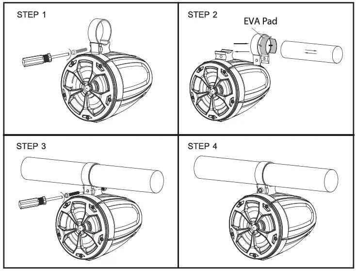
Auto Reconnection:
- Step 1: Unbolting the mounting bracket.
- Step 2: Slide in the buckle with a rubber pad attached to the bracket stand of the speaker. Attach the set to the handlebar of the vehicle/ship.
- Step 3/4: Attach the screw to lock the buckle.
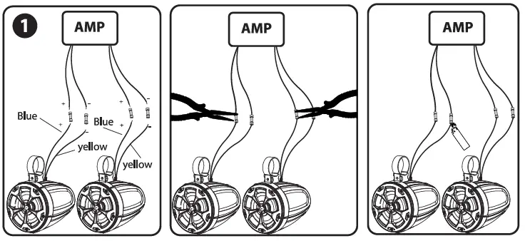
- Step 5: Use Butt Connector accessories to Connect Speaker wires (See Illustration 1,2,3).

FEATURES
- Waterproof Rated Speakers
- Pro Audio Power Sports Amplifier System Kit
- 2-Channel Marine Audio Amplifier
- Marine Grade Rugged Construction
- Waterproof Rated & Weather-Resistant Connectors
- Integrated Power Wiring Harness
- Perfect for Custom Installations & Applications
- Ability to Connect & Stream Audio from External Devices
- Wired RCA/AUX Audio Input
- Speaker Wiring Connectivity
- Anti-Thump Turn-On
- Soft Turn On / Off
- Pre-Amp RCA Out to Any OEM / Factory-Made Universal Mono Block/or Full Range Amplifier
- Overload & Power Protection Circuitry
- Used for Watercraft & Portable Mobile Vehicle Sound Systems
WHAT’S IN THE BOX
- (2) 4’’ -inch Marine Speakers
- Compact 2-Channel Marine Amp
- (2) 2 Meters Speaker Wire
- Audio Connection Cable, 3.5mm
- Owner’s Manual
- Warranty Card
- (2) 150x19x6mm (LxWxH) EVA Pads
- (2) 165x19x2mm (LxWxH) EVA Pads
- (4) Butt Connector (Red Color For A.W.G 16-22)
TECHNICAL SPECS
- Amplifier Type: 2-Ch. Audio Component
- Power Output: 800 Watt MAX
- 2 x 45 Watts RMS @ 4 Ohm
- 2 x 150 Watts MAX @ 4 Ohm
- Marine Grade IP-65 Rating
- H.D: 0.1%
- S/N Ratio: > 93dB
- Channel Separation: > 50dB
- Frequency Response: 20Hz-20kHz
- Fuse: 15A
- Power: DC 12V
- Amp Dimensions (L x W x H): 3’’ x 3.6’’ x 1.97’’ –inches
Warning: This product can expose you to a chemical or group of chemicals, which may include ”Di (2-Ethylhexyl) phthalate (DEHP)” which is known in the state of California to cause cancer, birth defects, or other reproductive harm. For more info, go to https://www.p65warnings.ca.gov/.
FAQs
Does the amplifier have an attenuator?
There is no attenuator on it. Please visit our website, pyleaudio.com, for more information. Enter PLUTV42CH in the search box as the model number.
Is it possible to get wet Pyle PLUTV42CH maritime speakers?
Marine surroundings can withstand products that are Marine Rated or Marine Grade. Marine grade parts can be exposed to rain, wind, and the sun (although not necessarily submersion). When a little water is splashed on them, they won’t burn because they can survive high ambient temperatures.
What materials are used in Pyle PLUTV42CH marine speakers?
Sea speakers are built with sturdy materials to ensure their durability in the more demanding marine environment. They are made of special plastic to withstand the elements and have stainless steel parts to withstand sudden temperature changes.
Is it possible to get wet Pyle PLUTV42CH maritime speakers?
Marine surroundings can withstand products that are Marine Rated or Marine Grade. Marine grade parts can be exposed to rain, wind, and the sun (although not necessarily submersion). When a little water is splashed on them, they won’t burn because they can survive high ambient temperatures.
What materials are used in Pyle PLUTV42CH marine speakers?
Sea speakers are built with sturdy materials to ensure their durability in the more demanding marine environment. They are made of special plastic to endure the environment and have stainless steel parts to tolerate rapid temperature changes.
Waterproof Pyle PLUTV42CH Marine audio?
For outside use, marine speakers are designed to withstand splashes, rain, and even hose water. They are waterproof, to use a phrase we like.
What materials are used in Pyle PLUTV42CH marine speakers?
Sea speakers are built with sturdy materials to ensure their durability in the more demanding marine environment. They are made of special plastic to endure the environment and have stainless steel parts to tolerate rapid temperature changes.
What does a marine grade Pyle PLUTV42CH speaker do?
Shop weatherproof and direct weather speakers for marine environments, exposure to corrosive atmospheres, outdoor use, and other applications.
What does Pyle PLUTV42CH maritime speaker stand for?
To be referred to as marine certified, a speaker must pass rigorous maritime testing by the American Society for Testing and Materials. Here, UV light and sea fog are used to assess the durability of the speakers.
What are the applications for Pyle PLUTV42CH marine speakers?
The marine audio system, which is used to play music on boats, consists of a number of speakers, amplifiers, and other gadgets.
Are the Pyle PLUTV42CH marine speakers bass-friendly?
The marine speaker has a good full-range sound response between 80 Hz and 20 kHz and produces passable bass performance.
How can I improve the audio quality on my boat speakers?
Install the required marine audio equipment, choose a suitable design, and confirm that your boat is correctly wired. Select the perfect speaker setup for high-quality audio. Make your audio system future-proof. A trained marine audio installer should set up a sound system.
Do you need an amp for wakeboard tower speakers?
They lack the power to play loudly in front of a boat that is moving quickly on their own. Distortion could be caused by the quick sound dispersion. And this might make wakeboarding unpleasant. Fortunately, by using the appropriate marine amplifier, you can maximize the performance of these tower speakers.
Do wake tower speakers have good bass?
Even when placed far from the source over water, these models still produce a wide spectrum of sound. They don’t sacrifice clarity and deliver strong highs and deep bass.


