![]() Manual version: 1.0.A
Manual version: 1.0.A
Product code: G2009
Product Version: 1.0
G2009A1 SOLAR SIMULATOR
LED Solar Simulator Lamp
User Manualb
Overview
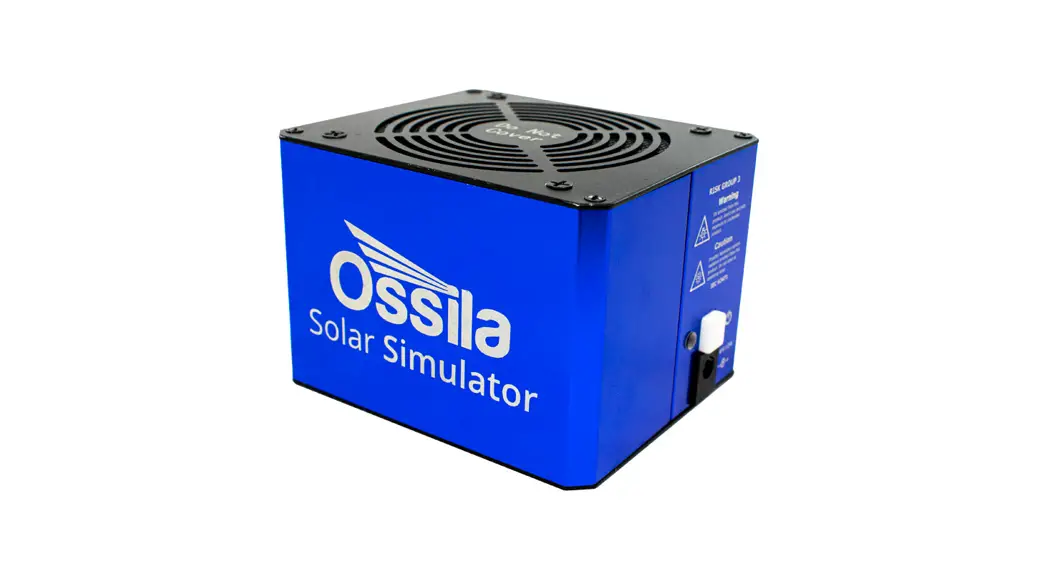
The Ossila Solar Simulator is a small area, LED-based steady-state solar simulator. It can be used as a stand-alone unit or integrated into the Ossila Solar Cell I-V Test Systems for a complete characterisation system. Providing class AAA performance (IEC 60904-9:2020 Edition 3.0) over a 15 mm diameter area, it is an affordable solution for photovoltaic characterisation and any other analysis requiring an artificial solar spectrum.
The Ossila Solar Simulator is part of our Solar Cell Prototyping Platform, a complementary collection of substrates, materials, and equipment as part of a high-performance standard photovoltaic reference architecture. This platform enables researchers to produce high-quality, fully functional solar cells which can be used as a reliable baseline.
For more information: ossila.com/pages/solar-cell-prototyping-platform. 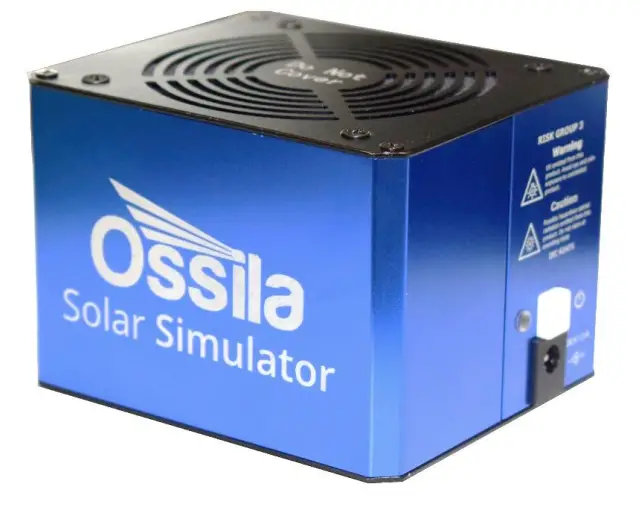
EU Declaration of Conformity (DoC)
We
Company Name: Ossila BV
Postal Address: Biopartner 3 building, Galileiweg 8
Postcode: 2333 BD Leiden
Country: The Netherlands
Telephone number: +31 (0)71 3322992
Email Address: [email protected]
declare that the DoC is issued under our sole responsibility and belongs to the following product:
Product: Solar Simulator (G2009A1), Solar Simulator with Manual Stage (G2009B1)
Serial number: G2009A1-xxxx
Object of declaration:
Solar Simulator (G2009A1)
The object of declaration described above is in conformity with the relevant Union harmonisation legislation:
EMC Directive 2014/30/EU
RoHS Directive 2011/65/EU
Photobiological safety of lamps and lamp systems IEC 62471:2006
Signed:  Name: Dr James Kingsley
Place: Leiden
Date: 16/11/2021
Safety
3.1 Use of Equipment
The Ossila Solar Simulator is designed to be used as instructed. It is intended for use under the following conditions:
- Indoors in a laboratory environment (Pollution Degree 2)
- Altitudes up to 2000m
- Temperatures of 5°C to 40°C; maximum relative humidity of 80% up to 31°C.
The unit is supplied with a 24 VDC power adapter, in accordance with European Commission regulations and British Standards. Use of any other electrical power cables, adaptors, or transformers is not recommended.
3.2 Hazard Icons
The following symbols can be found at points throughout the rest of the manual. Note and read each warning before attempting any associated operations associated with it:
Table 3.1. Hazard warning labels used in this manual.
| Symbol | Associated Hazard |
| Electrical shock | |
| Optical radiation | |
| Ultraviolet radiation |
3.3 Power Cord Safety![]() Emergency power disconnect options: use the power cord as a disconnecting method and remove from wall. To facilitate disconnect, make sure the power outlet for this cord is readily accessible to the operator.
Emergency power disconnect options: use the power cord as a disconnecting method and remove from wall. To facilitate disconnect, make sure the power outlet for this cord is readily accessible to the operator.
3.4 Optical Hazards![]() The Ossila Solar simulator emits intense optical radiation in the ultraviolet, visible, and infrared regions of the electromagnetic spectrum. The device has been assessed according to IEC 62471:2006 (Photobiological safety of lamps and lamp systems) and assigned to Risk Group 3.
The Ossila Solar simulator emits intense optical radiation in the ultraviolet, visible, and infrared regions of the electromagnetic spectrum. The device has been assessed according to IEC 62471:2006 (Photobiological safety of lamps and lamp systems) and assigned to Risk Group 3.
3.5 Servicing
If servicing is required, please return the unit to Ossila Ltd. The warranty will be invalidated if:
- Modification or service has been carried out by anyone other than an Ossila engineer.
- The Unit has been subjected to chemical damage through improper use.
- The Unit has been operated outside the usage parameters stated in the user documentation associated with the Unit.
- The Unit has been rendered inoperable through accident, misuse, contamination, improper maintenance, modification, or other external causes.
Requirements
Table 4.1 details the power requirements and connectivity of the Ossila Solar Simulator.
Table 4.1. Ossila LED Measurement System requirements.
| Power | 24 VDC |
| Connectivity | USB-C |
Unpacking
5.1 Packing List
The standard items included with the Ossila Solar Simulator (G2009A1) are:
- The Ossila Solar Simulator lamp.
- 24 VDC, 45 W power adaptor.
- USB memory stick loaded with data sheet, calibration data, and test data.
5.2 Damage Inspection
Examine the components for evidence of shipping damage. If damage has occurred, please contact Ossila directly for further action. The shipping packaging will come with a shock indicator to show if there has been any mishandling of the package during transportation.
Specifications
The Ossila Solar Simulator specifications are shown in Table 6.1. See the data sheet included with the Solar Simulator for detailed specifications of the unit.
Table 6.1. Ossila Solar Simulator specifications.
| Solar simulator type | Steady state |
| Illumination source | LED |
| Spectral match classification | A |
| Spatial non-uniformity classification (minimum diameters) | 15 mm – A 25 mm – B 32 mm – C |
| Temporal instability classification | A |
| Spectral deviation | <70% |
| Spectral coverage | >80% |
| Working distance | 85 mm |
| Warm up time | 5 minutes |
| Dimensions | Length: 105 mm; Width: 90 mm; Height: 80 mm |
| Weight | 600 g |
System Components
The Ossila Solar Simulator Lamp is supplied with a 24 VCD, 45 W power adapter. 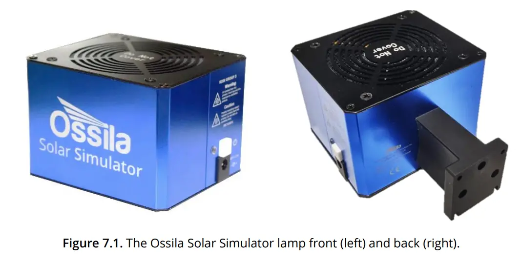
Installation
The solar simulator lamp should be mounted appropriately such that air is free to circulate above and below the unit. There are 3 available mounting options:
- Height adjustable stage (sold separately). The solar simulator lamp bracket is directly attached to the Z-stage platform, allowing manual adjustment of the lamp height. The lamp is attached to the stage using four M3 bolts as shown in Figure 8.1.
 Figure 8.1. Mounting positions for attaching the Solar Simulator to the vertical stage platform.
 - Fixed bracket integrated with the Ossila Solar Cell I-V Test System – Automated (sold separately). The solar simulator lamp is affixed to a bracket mounted onto the automated version of the Ossila Solar Cell I-V Test System with four M3 bolts. There are two possible mounting positions available. The lower position is used when a 20 x 15 mm substrate measurement bracket is attached to the IV system, while the higher position is used when a 25 x 25 mm substrate measurement bracket is attached to the I-V system. The two possible positions are shown in Figure 8.2.
 Figure 8.2. Bracket for mounting Solar Simulator on an Ossila Solar Cell I-V Test System – Automated. Left mounting is for 20 x 15 mm substrates, right for 25 x 25 mm substrates.
 - Custom mounting. The solar simulator lamp can be mounted to any user-supplied mounting platform using four M3 bolts and/or two M6 bolts, so long as there is unrestricted airflow 5 cm above and below the lamp unit. The mounting bracket dimensions are shown in Figure 8.3
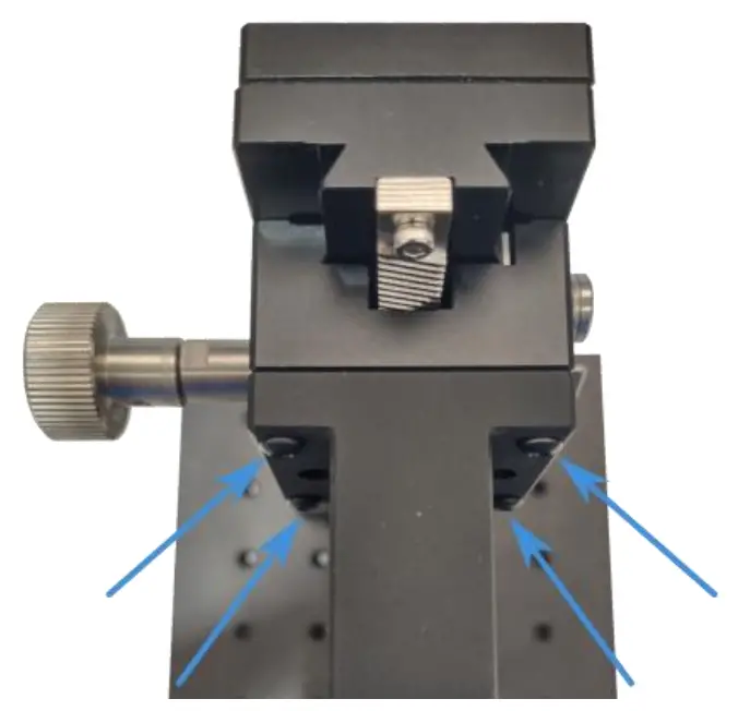 Figure 8.1. Mounting positions for attaching the Solar Simulator to the vertical stage platform.
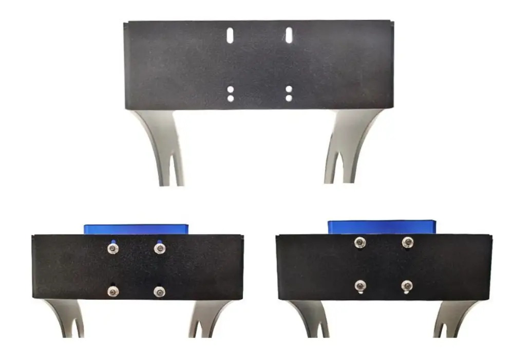 Figure 8.2. Bracket for mounting Solar Simulator on an Ossila Solar Cell I-V Test System – Automated. Left mounting is for 20 x 15 mm substrates, right for 25 x 25 mm substrates.
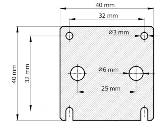 Figure 8.3. Mounting bracket dimensions.
Mount the solar simulator lamp according to one of options above. Connect the 24 VDC power adaptor to the power socket on the side of the unit.
Operation
When the system is first powered on, the light output will be 1 Sun (1000 W/m² ) at 85 mm below the bottom faceplate of the system. While the LEDs are turning on, the ndicator light (next to the power button) will illuminate white. When the system reaches one sun after approximately 2 seconds, the indicator light will turn green. We suggest leaving the system to run for 5 minutes before starting measurements to allow the system temperature and LED output to stabilise.
The colour of the indicator light specifies the system operating conditions as listed in Table 9.1.
Table 9.1. Indicator light meanings.
| Indicator Light Colour White | Meaning |
| White | System is changing LED power |
| Green | Output is 1 sun (100 mW/cm2) |
| Blue | Output is a calibrated power value other than 1 sun |
| Yellow | Output is uncalibrated (user has specified individual LED channel powers) |
| Intermittent flashing red | High temperature warning |
| Continuous flashing red | System error (see section 13). |
The Ossila Solar Simulator connects to a computer through a USB connection. The device has a USB-C port located on the underside of the lamp, as shown in Figure 9.1. A USB cable should be used to connect the solar simulator to the computer. Communication is only possible when the system is turned on.
Warning: Ensure that the system is powered off when plugging and unplugging a USB cable.![]()
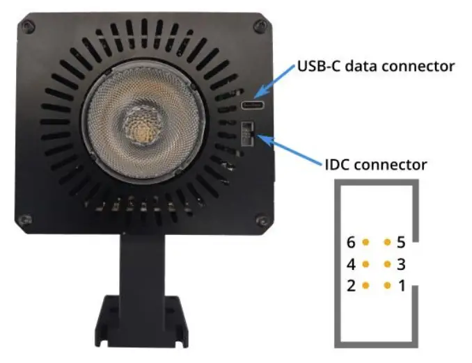 Figure 9.1. Connectivity ports of the Solar Simulator.
An external shutter control pin is provided through the IDC connector interface. The shutter pin is controlled through a serial command (see Section 11.2).
Table 9.2. ICD connector pin layout.
| Pin | Function |
| 1 | Shutter |
| 2 | GND |
| 3 | NC |
| 4 | NC |
| 5 | NC |
| 6 | GND |
Maintenance
The Ossila Solar Simulator is a sealed unit and requires no maintenance if used under the recommended conditions.
11. Command Library
The solar simulator communicates with a host computer through a serial command library. When connected to a PC, the system will appear as a COM port, to which the serial commands could be sent. This section describes the command protocol and lists the available commands.
10.1 Command Format
Commands should be sent to the solar simulator in ASCII format, and responses from the solar simulator will also be in ASCII format.
All commands sent to the solar simulator have a start and end delimiter, < and > respectively. Only commands enclosed by these delimiters will be acknowledged by the device. If any invalid commands are sent between delimiters, the system will return <Invalid Command>. Commands can be setting commands or query commands.
Setting commands have the format <parameter:value>, where parameter is the setting to be changed, and value is the new value. The new value will be either a floating-point number, integer, or Boolean (0 or 1). Floating point numbers can be sent in scientific notation (e.g., 123e4 or 123E4).
If a command requires an integer and a floating-point value is sent, the system will round the number down to an integer. If a Boolean is required and a non-zero floating-point number (or integer other than 0 or 1) is sent, the system will interpret it as a 1. If a setting command is successfully implemented, the system will echo back the command.
Query commands have the format <parameter?>. These commands allow the user to find current system settings without modifying them. If a query command is successfully interpreted, the system will return <parameter:value>./
11.2 Setting Command List
| Command | Function | Expected Value |
| <power:value> | Sets the calibrated irradiance at the working distance. | 0 or integer between 10 and 100. This is the irradiance (in mW/cm² ). Irradiances calibrated at every 10 mW/cm 2are stored in the system memory (i.e., 10 mW/cm² , 20 mW/cm² , 30 mW/cm² etc.). Power can be set at an intermediate value, but the LED powers will be based on an interpolation between the calibrated values. |
| <chX:value> | Sets the power of LED channel X (see Table 11.1). | Integer between 0 and 100. This is the power in % of the maximum LED power. Setting an LED power in this way will put the system in to custom power mode. |
| <save:1> | Save the current setting to memory so that it is recalled when the system is powered on. | |
| <shutter:value> | Activates or deactivates shutter pin. | 0 (output is 0V) or 1 (output is 3.3V). |
11.3 Query Command List
| Command | Function | Function |
| <power?> | Returns the current | <power:value> where value is an integer between 0 and 100, representing the irradiance (in mW/cm 2 ). If the system is in custom power mode, the device will return ² <power:undef>. |
| <chX?> | Returns the % power of LED channel X(see Table 11.1) | <chX: value> where vaLue is an Integer. |
| <device?> | Returns the device name. | <device:G2009> |
| <firmware?› | Returns the firmware number. | <firmware: value> where value is the firmware version (returned as a float). |
| <serial?> | Returns the serial number. | <serial:value> where value is the serial number (returned as an integer). |
| <temp?› | Returns the system temperature. | <temp: vaLue> where vaLue Is the temperature In degrees Celsius. |
| <shutter?> | Returns the state of the shutter pin. | <shutter : value> where value is either 0 (shutter pin at OV) or 1 (shutter pin at 3.3V). |
| <ledtime?› | Returns the total time the LED has been active. | <ledtime: value> where value is the number of minutes at least one LED channel has been turned on. |
| <error?› | Returns the current error state. | <error: value> where vaLue is either: 0 – no error 1 – low voltage detected 2 – high temperature 3 – LED fault If an error other than 0 is returned, please see Section 13. |
11.4 LED Channels
Table 11.1. LED channels and their central wavelengths.
| Channel | Central Wavelength |
| 1 | 390 nm |
| 2 | 450 nm |
| 3 | 515 nm |
| 4 | Cool white (400 – 750 nm) |
| 5 | Warm white (400 – 800 nm) |
| 6 | 600 nm |
| 7 | 630 nm |
| 8 | 660 nm |
| 9 | 730 nm |
| 10 | 850 nm |
| 11 | 950 nm |
Example Code
The following code is written in the Python programming language and shows how to set up the device, read, and plot a spectrum.
# The PySerial library is required to communicate with the solar simulator
# Ensure that it is installed on your system before running this script import serial
# Open a serial connection to the solar simulator
# Here we use the ‘with’ statement to connect to the Solar Simulator, as this will automatically
# handle closing the connection when the with-block is exited, even if an error occurs
# In this example, the Solar Simulator is attached to COM port 18
# It is likely to be a different port on your computer
# In windows, you can see which port has been assigned in the Device Manager with serial.Serial(‘COM18’) as simulator:
# We can read the current irradiance from the device using the <power?> command
# The command needs to be converted into a byte array before being sent to the spectrometer
# This is done using the encode() function simulator.write(‘<power?>’.encode())
# The solar simulator will return the current irradiance
# We can read its response with the readline() function
# The decode() function is used to convert the response to a string response = simulator.readline().decode()
# If we print the response, we will see <power:xxx> where xxx is the irradiance at the working
# distance in in mW/cm^2 print(response)
# The irradiance can be changed using the <power:xxx> command
# Here we set it to 50 mW/cm^2 simulator.write(‘<power:50>’.encode())
# The spectrometer will echo back the command if successful response = simulator.readline().decode()
# The response will be <power:50> print(response)
# Once the script is complete, close the interface to the solar simulator simulator.close()
Troubleshooting
Most of the issues that may arise will be detailed here. However, if you encounter any issues that are not detailed here, then contact us by email at [email protected]. We will respond as soon as possible.
| Problem | Possible | Action |
| No power. | The power supply may not be connected properly. | Ensure the system is firmly plugged into the power supply, and that the plug is connected to both the adaptor and a working power socket. |
| The power supply adaptor has a fault. | Contact Ossila for a replacement power supply adaptor. | |
| The system loses power. | Incorrect power adapter. | Ensure that the power adapter is 24V and can supply a minimum of 1.87A |
| Cannot connect to the system via USB. | The USB cable may not be connected properly. | Ensure the USB cable is firmly plugged in at both ends. |
| The USB cable may not be connected to a working USB port. | Try connecting the unit to a different USB port on the computer. | |
| The USB cable is defective. | Try using a different USB-B cable and contact Ossila if necessary. | |
| Intermittent red flashing indicator light. Solar simulator output is on. | High temperature. | Reduce ambient temperature if possible. Ensure vents at the top and bottom of the system are not blocked. |
| Continuous red flashing indicator light. Solar simulator output is off. | Low Input voltage. System will return error code 1. | Ensure the correct power adapter (24V) is used. |
| Temperature limit exceeded. System will return error code 2. | Turn off the system and allow to cool. | |
| LED failure. System will return error code 3. | Contact Ossila for repair. | |
| The indicator LED does not turn green. | The start-up power has been modified. | Use the USB connection to send the command <power:100> followed by <save:1> to reset it to 1 sun. |
14.1 Related Consumables 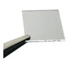 ITO Coated Substrates
Our range of ITO substrates for OPV, OLED, and sensing applications.
Product codes: S111 / S211 / S2006  FTO Coated Substrates
Designed to be used as transparentelectrodes for thin-film photovoltaics.
Product codes: S301 / S302 / S303 / S304 Flat Tip Tweezers
Provides a good substrate grip without scratching. Product code: C121 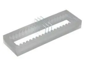 Substrate Cleaning Rack
Holds 20 substrates for a variety of processing techniques.
Product codes: E101 / E102
14.2 Related Equipment  Solar Cell I-V Test System
Reliable and accurate characterisation of photovoltaic devices – no programming knowledge necessary!
Product codes: T2002 / T2003  Push-Fit Test Boards
For fast and secure electrical connections, this product makes PV and OLED device testing easy.
Product code: P2008A1 / P2011A1 / P2012A1 Source Measure Unit
Source voltage, measure current, get data. Simplify and accelerate your data collection!
Product code: P2005A2 Spin Coater
Product high-quality coatings without any substrate warping. Perfect for busy labs with limited space.
Product code: L2001A3
Ossila.com
Ossila Limited © 2022


