ProPlex Floppy Drive Digital Portable Mount
INTRODUCTION
PRODUCT OVERVIEW
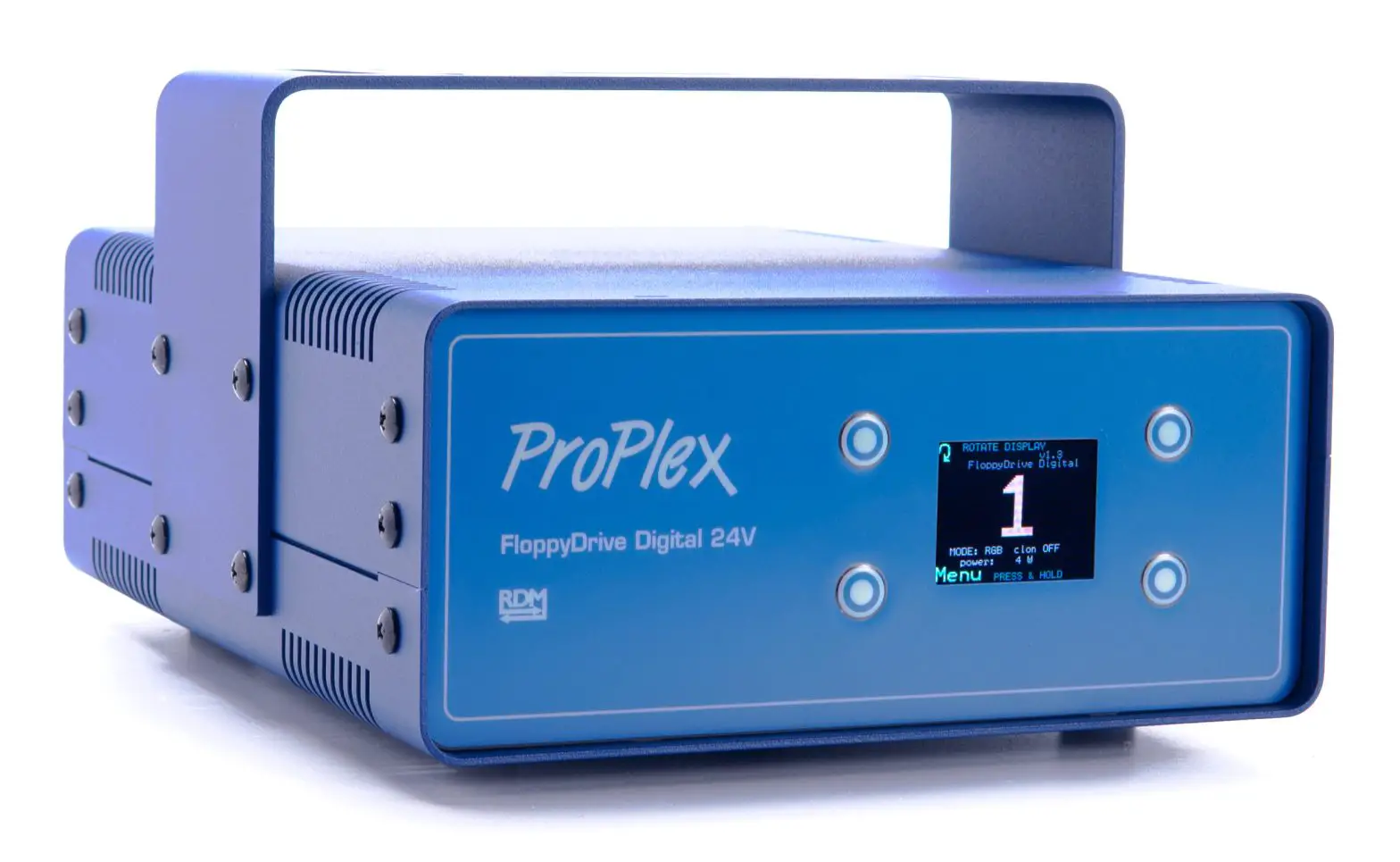
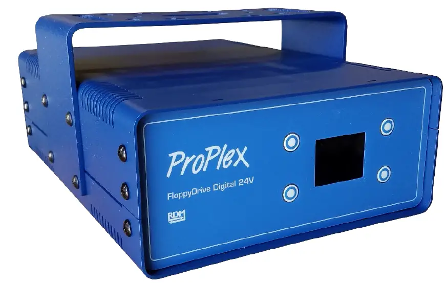
The ProPlex FloppyDrive Digital is a 24V DMX controller for Floppy Flex Digital LED neon. Features include:
- Rugged, tour-ready ProPlex “Blue Box” PortableMount chassis. Packaged for extreme Conditions. Shock-mounted circuitry. Advanced thermal management
- Many onboard preprogrammed “looks” with RGB presets
- Perfect for Firefly FloppyFlex Digital RGB LED neon. Connect 1 x 15-meter run.
- Color LCD Display with easy function control buttons for easy setup and configuration
- Heavy-duty yoke for truss mounting. Optional RackMount Kit available.
- One 24VDC, Floppy Flex Digital RGB output
- RDM functionality for complete system monitoring and addressing via RDM
- Self-healing overcurrent / short circuit protection
- Neutrik connectors throughout
UNPACKING INSTRUCTIONS
Upon receipt of the unit, carefully unpack the carton and check the contents to ensure that all parts are in good condition. Notify the shipper immediately and retain packing material for inspection if any parts appear to be damaged from shipping or if the carton itself shows signs of mishandling. Save the carton and all packing materials. If a unit must be returned to the factory, it is important that it unit be returned in the original factory box and packing.
POWER REQUIREMENTS
Before powering the unit, make sure the line voltage is within the range of accepted voltages. This unit accommodates 90-240 VAC, 50/60 Hz. All units must be powered directly from a switched circuit and cannot be operated with a rheostat (variable resistor) or dimmer circuit, even if the rheostat or dimmer channel is used solely for a 0-100% switch.
SAFETY INSTRUCTIONS
WARNING: Please read these instructions carefully. This user manual contains important information about the installation, usage and maintenance of this product.
- Keep this user manual for future reference. If unit is sold to another user, make sure they also receive this instruction booklet.
- Ensure the unit is connected to proper voltage, and that line voltage is not higher than that stated on the device.
- Make sure there are no flammable materials close to the unit while operating.
- Always disconnect from the power source before servicing or fuse replacement. Always use the fuse specified in this manual.
- Always use a safety cable when hanging unit overhead.
- Maximum ambient temperature (Ta) is 40 °C (104 °F). Do not operate unit at temperatures above this rating.
- In the event of a serious operating problem, stop using the unit immediately. Repairs must be carried out by trained, authroized personnel. Conact the nearest authorized technical assistance center. Only OEM spare parts should be used.
- Do not connect the device to a dimmer pack.
- Make sure power cord is never crimped or damaged.
- Never disconnect power cord by pulling or tugging on the cord.
Caution! There are no user serviceable parts inside the unit. Do not open the housing or attempt any repairs yourself. In the unlikely event your unit may require service, please contact your distributor.
WARNING: Disconnect the power cord before replacing a fuse and always replace with the appropriate fuse.
FUSE REPLACEMENT
The FloppyDrive Digital uses a 6.0A, 250V barrel fuse, 5x20mm (0.2×0.8 in.). To replace fuse:
- With a screwdriver turn the fuse cap counter-clockwise to remove fuse cap with fuse.
- Replace fuse attached to fuse cap.
- Reinsert fuse cap with new fuse and tighten clockwise
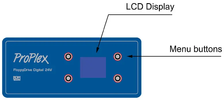
PANEL FRONT: FLOPPYDRIVE DIGITAL 24V
PANEL REAR: FLOPPYDRIVE DIGITAL 24V
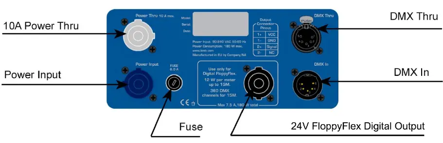
FEATURES
1 LED strip output for use with FloppyFlex Digital
24V DC output
Maximum 180 W total power
Power input- 90-240 VAC, 50/60Hz
LINKING
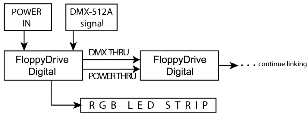
1) Connect the male 5-pin XLR connector of the DMX cable to the output (female) 5-pin XLR connector of the DMX console.
2) From the DMX console, connect the female 5-pin XLR connector of the DMX cable to the input connector (male) of the ProPlex RGB Drive.
3) Connect from the fixture output as stated above to the input of the following FloppyDrive and so on.
4) Continue the link until last FloppyDrive Digital is connected in your DMX signal data chain.
5) Attach LED strips to each ProPlex FloppyDrive as planned.
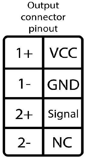
LED STRIP PIN OUT
RGB LED strip connection pin out.
Note: NC Connector does not get connected
OPERATION
NAVIGATING THE CONTROL PANEL
Access control panel functions using the four control panel buttons surrounding the LCD display.
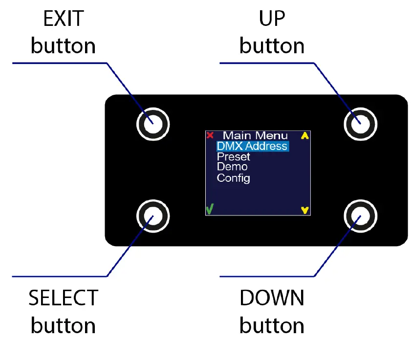
Press and hold the <MENU> button to scroll through the top level menu items. This is the top of the menu map. Use the <UP> and <DOWN> buttons, located right from LCD screen,
to navigate the menu map and menu options.
Press the <SELECT> button to access the menu function currently displayed or to enable a menu option. To return to the top of the menu map or menu without changing the value, press the <EXIT> button.
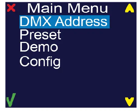
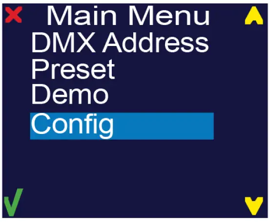
Main Menu Functions:
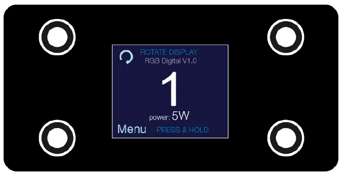
During normal operation of the ProPlex FloppyDrive Digital, the LCD of the control panel displays the current DMX address. If the unit is not receiving a DMX signal, the address blinks in RED color.
| Level 1 | Level 2 | Level 3 | Function |
| DMX Address | Set the DMX start address | ||
| Preset | This mode is made for stand-alone DMX | ||
| RED | 000 ↔ 255 | Set the DMX value from 0-100% for RED color | |
| GREEN | 000 ↔ 255 | Set the DMX value from 0-100% for GREEN color | |
| BLUE | 000 ↔ 255 | Set the DMX value from 0-100% for BLUE color | |
| DEMO | Pre-programmed fixture tests. | ||
| Demo 1 | Red color test | ||
| Demo 2 | Green color test | ||
| Demo 3 | Blue color test | ||
| Demo 4 | White color test | ||
| Demo 5 | Yellow color test | ||
| Demo 6 | Cyan color test | ||
| Demo 7 | Magenta color test | ||
| Demo 8 | RGBW Full test | ||
| Demo 9 | Rainbow Long test | ||
| Demo 10 | Rainbow short test | ||
| Demo 11 | Rainbow + Run Soft test | ||
| Demo 12 | Rainbow + Run Hard test | ||
| Demo 13 | White + Run hard test | ||
| Demo 14 | Strobe Red test | ||
| Demo 15 | Strobe Green test | ||
| Demo 16 | Strobe Blue test | ||
| Demo 17 | Strobe White test | ||
| Config | Configuration menu | ||
| DMX hold | Select what will happen after fixture loses its DMX signal | ||
| ON | Holds the last received DMX values when DMX signal is lost | ||
| OFF | Does not hold the last received DMX values when DMX signal is lost and stops light output | ||
| Backlight | Screen backlight setting | ||
| Always ON | Backlight is always ON | ||
| OFF in 10s | Backlight will turn OFF in 10s of idle |
DMX ADDRESS
To set the required DMX address, you must:
- Press and hold <MENU> button to open the Main Menu.
- Use <UP> and <DOWN> buttons to find the ”DMX Address” submenu.

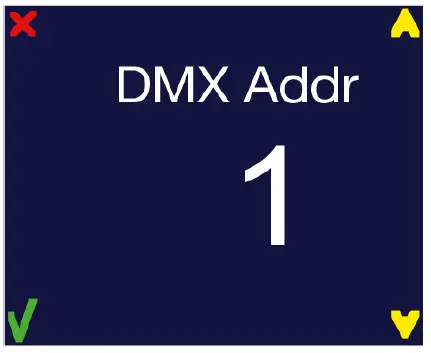
- Press <Select> button to access the DMX address value change submenu.
- Use <UP> and <DOWN> buttons to set necessary DMX address value (for example: “DMX Addr: 1”).

- Use <SELECT> button to confirm the new DMX address.
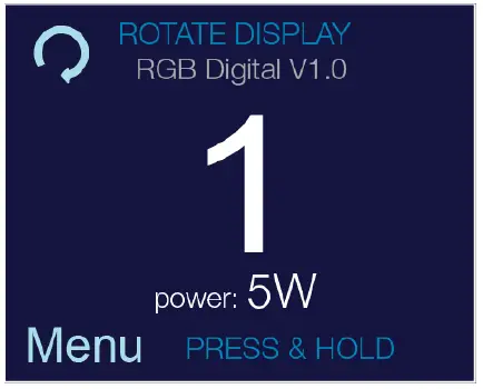
- When the new DMX address is confirmed, Main Menu appears. Press <EXIT> button to return the working state.
- Working state control panel display shows current DMX address, in this case it is 1.
Furthermore, the current power usage can be seen there (in this case it is 5 W).
CONTROL
The FloppyDrive Digital LED neon strip controller has one default 3-channel controlling mode which can’t be changed.
| Channel | Value | Function | Pixel numb. |
| 1 | 000 ↔ 255 | RED intensity 0% – 100% | 1 |
| 2 | 000 ↔ 255 | GREEN intensity 0% – 100% | 1 |
| 3 | 000 ↔ 255 | BLUE intensity 0% – 100% | 1 |
| 4 | 000 ↔ 255 | RED intensity 0% – 100% | 2 |
| 5 | 000 ↔ 255 | GREEN intensity 0% – 100% | 2 |
| 6 | 000 ↔ 255 | BLUE intensity 0% – 100% | 2 |
| … | … | … | … |
| … | … | … | … |
| … | … | … | … |
| 358 | 000 ↔ 255 | RED intensity 0% – 100% | 120 |
| 359 | 000 ↔ 255 | GREEN intensity 0% – 100% | 120 |
| 360 | 000 ↔ 255 | BLUE intensity 0% – 100% | 120 |
Each meter of FloppyFlex Digital consists of 8 pixels. Each meter of FloppyFlex Digital takes 24 DMX channels (8 pixels x 3 RGB channels).
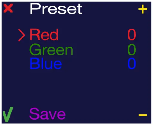
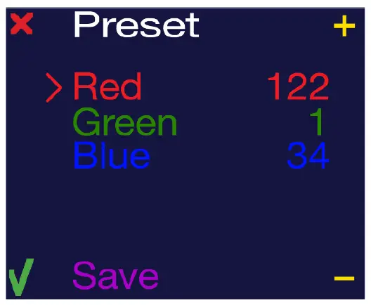
Preset – This is a manual stand-alone mode where you can set your LED strips as a static RGB wash. Even if the fixture is turned off and on, the preset mode values will be saved.
To work with preset mode, there are 3 settings:
• RED (000 ↔ 255) – intensity of RED color
• GREEN (000 ↔ 255) – intensity of GREEN color
• BLUE (000 ↔ 255) – intensity of BLUE color
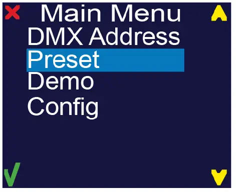
- Press and hold <MENU> button to open the Main Menu.
- Use <UP> and <DOWN> buttons to find the Preset submenu and press <Select> button.

- Manual mode submenu will open.
- RED – color intensity (000 ↔ 255)
- GREEN – color intensity (000 ↔ 255)
- BLUE – color intensity (000 ↔ 255)

- To change values of preset mode, you use the <+> and < – > buttons. After selecting the desired value of the first color (RED), press the <SELECT> button to edit the next value in the list (BLUE). When all values have been set as desired, select “Save”. It will flash “Saved”.

- Now the device should have a LED output.
- Press <EXIT> button. All settings will be saved.
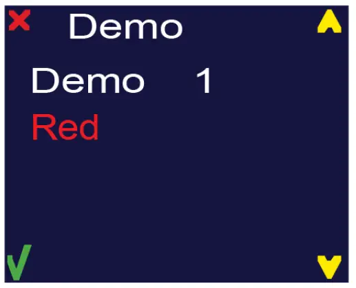
DEMO
in this menu, select the following demo scenes:
- Red color test
- Green color test
- Blue color test
- White color test
- Yellow color test
- Cyan color test
- Magenta color test
- RGBW Full test
- Rainbow Long test
- Rainbow short test
- Rainbow + Run Soft test
- Rainbow + Run Hard test
- White + Run hard test
- Strobe Red test
- Strobe Green test
- Strobe Blue test
- Strobe White test
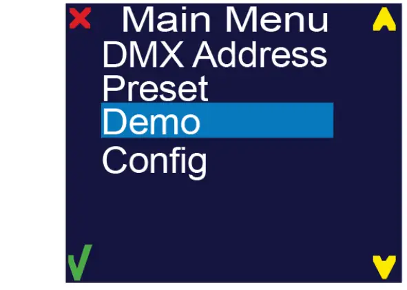
- Press and hold <MENU> button to open the Main Menu.
- Use <UP> and <DOWN> buttons to find the Demo submenu and press select button.

- Choose the desired demo using <UP> and <DOWN> buttons.
After the demo has completed playback, press <SELECT> or <EXIT> button to return to the main menu.
CONFIG
Under this menu, change the devices configuration settings.
- Press and hold <MENU> button to open the Main Menu.
- Use <UP> and <DOWN> buttons to find the Demo submenu and press select button.

- Another submenu will open:
- Using <UP> and <DOWN> buttons choose the setting to be modified and press the <SELECT> key.

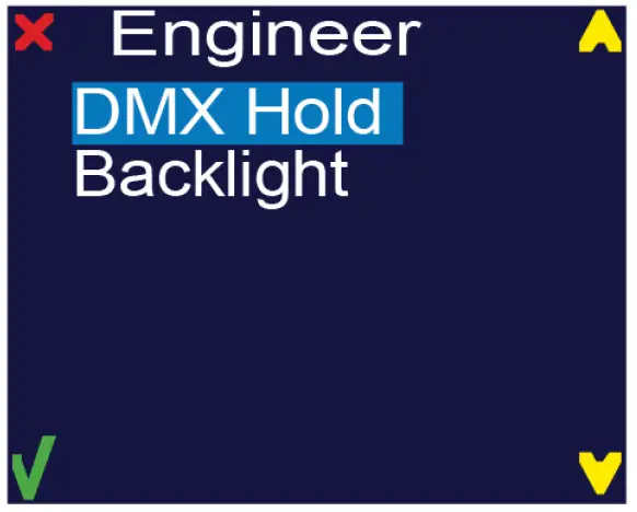
DMX HOLD
Set the FloppyDrive’s reaction to lost DMX signal.
HOLD – Holds the last received DMX values when DMX signal is lost
OFF – Doesn’t hold the last received DMX values when DMX signal is lost; stops light output.
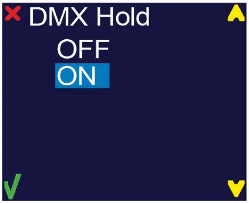
Use <UP> and <DOWN> keys to find the desired option and press <SELECT> button. After selecting correct setting, press <EXIT> key to exit this submenu.
BACKLIGHT – Display backlight settings
Always ON – Backlight is always turned on
OFF in 10s – Backlight is turned off after 10 seconds of idle.
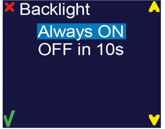
Use <UP> and <DOWN> keys to find the desired option and press <SELECT> button. After selecting correct setting, press <EXIT> key to exit this submenu.
INSTALLATION
MOUNTING / RIGGING
Orientation – ProPlex Mini units may be mounted in any position, using the standard yoke. Always make sure there is adequate room for ventilation.
Rigging – Always consult a certified rigging specialist before suspending any device overhead.
Use ProBurger® couplers or equivalent C- or O-type clamps for attaching to truss. After establishing the desired position, tighten all appropriate bolts.
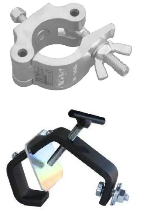
• Always use safety cables!
• When selecting installation location, consider routine maintenance.
• Never mount Mini enclosure where it will be exposed to moisture, high humidity, extreme temperatures, or restricted ventilation.
RACKMOUNT KIT
Optional RackMount Kits are available for mounting a ProPlex PortableMount enclosure in a 19” EIA rack.
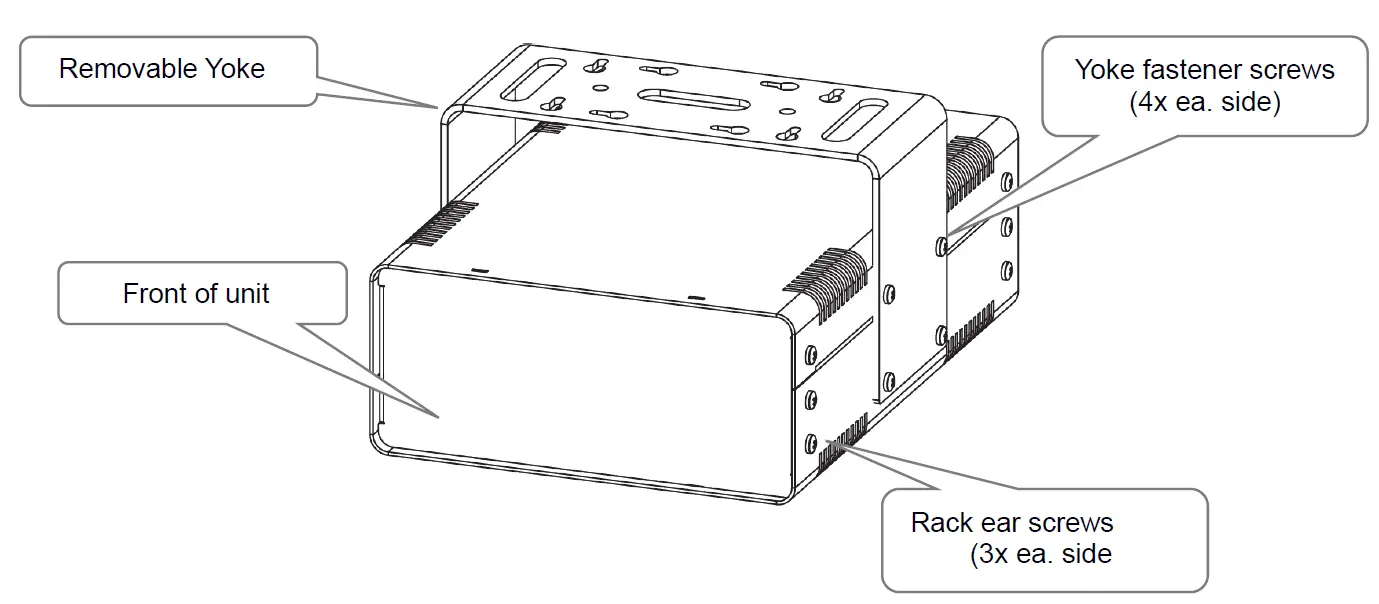
- ProPlex PortableMount enclosures include a yoke for truss mounting. Before attaching any RackMount Kit, remove the yoke by unscrewing the four Phillips-head screws which fasten the yoke to the chassis.
Important: Regardless of the configuration of the specific RackMount Kit being installed, all original yoke screws must be installed back into the ProPlex PortableMount device. - The 2U RackMount Kit Single is comprised of two rack ears, one long and one short. To fasten the ears to the ProPlex PortableMount chassis, remove the three chassis screws that align with the rack ear mounting holes at the front of the chassis. Then use the same screws to securely fasten the ears to the chassis, per below illustrations. The short and long ears included in the RackMount Kit can be mounted to either side of the chassis.

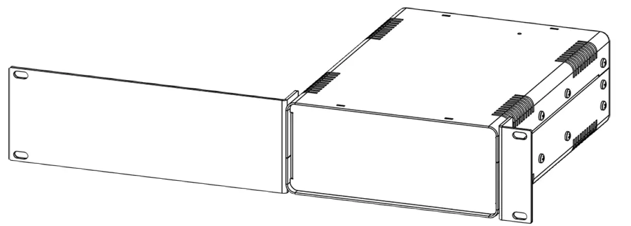
- The drawing below depicts the 2U Large Single RackMount Kit attached to a FloppyDrive PortableMount.

- Caution: Rack-Mounting ProPlex FloppyDrives. ProPlex LED Drives must have adequate airflow. When installing multiple units, they must be mounted on alternating sides of the rack, so one is NOT located directly above another, with at least one-half 1U space between each assembly, per below illustration.

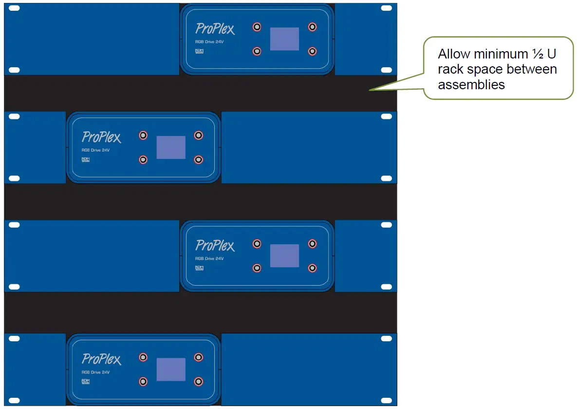
Warning: Placing two FloppyDrives directly next to each other – vertically or horizontally
in a rack or enclosed space will prevent adequate air circulation and may result in overheating of the device. Misapplication will void the warranty of the ProPlex device.
Appendix
RDM FUNCTIONALITY
ProPlex FloppyDrive Digital PortableMount devices have RDM Functionality. Below are the RDM functions available in these devices. TMB has many options for RDM control of your devices: ProPlex RDMigo and ProPlex Software; ProPlex Striker; and ProPlex MasterFade. Additionally, ProPlex RDM Opto-Splitters and the ProPlex IQ product range offer many means of RDM over DMX data distribution.
| Main | Display | Temperature |
| Mode | Display invert | Lowest value |
| DMX address | Display level | |
| RDM version | ||
| Software version |
LIMITED WARRANTY
ProPlex Data Distribution Devices are warranted by TMB against defective materials or workmanship for a period of two (2) years from the date of original sale by TMB.
TMB’s warranty shall be restricted to the repair or replacement of any part that proves to be defective and for which a claim is submitted to TMB before the expiration of the applicable warranty periods.
This Limited Warranty is void if the defects of the Product are the result of:
• Opening the casing, repair, or adjustment by anyone other than TMB or persons specifically authorized by TMB.
• Accident, physical abuse, mishandling, or misapplication of the product.
• Damage due to lightning, earthquake, flood, terrorism, war, or act of God.
TMB will not assume responsibility for any labor expended, or materials used, to replace and/or repair the Product without TMB’s prior written authorization. Any repair of the Product in the field, and any associated labor charges, must be authorized in advance by TMB. Freight costs on warranty repairs are split 50/50: Customer pays to ship defective product to TMB; TMB pays to ship repaired product, ground freight, back to Customer.
This warranty does not cover consequential damages or costs of any kind.
A Return Merchandise Authorization (RMA) Number must be obtained from TMB prior to return of any defective merchandise for warranty or non-warranty repair. For all repairs please contact TMB Tech Support Repair using the contact information below or email [email protected]
US
527 Park Ave.
San Fernando, CA 91340
Tel: +1 818.899.8818
Fax: +1 818.899.8813
[email protected]
www.tmb.com
UK
21 Armstrong Way Southall, UB2 4SD England
Tel: +44 (0)20.8574.9700
Fax: +44 (0)20.8574.9701
[email protected]
www.tmb.com
RETURN PROCEDURE
Please send returned merchandise prepaid and in the original packing. Freight call tags will not be issued for shipping the product to TMB, but TMB will pay the freight for return to the customer. Clearly label package with a Return Merchandise Authorization Number (RMA #). Products returned without an RMA # will delay service. Please contact TMB and request an RMA # prior to shipping the unit. Be prepared to provide the model number, serial number, and a brief description of the cause for the return. Be sure to properly pack the unit; any shipping damage resulting from inadequate packaging is the customer’s responsibility. TMB reserves the right to use its own discretion to repair or replace product(s). Proper UPS packing or double-boxing will better ensure product integrity when shipped.
Note: If you are given an RMA #, please include the following information on a piece of paper inside the box:
1) Your name
2) Your address
3) Your phone number
4) The RMA #
5) A brief description of the symptoms
TECHNICAL SPECIFICATIONS – FLOPPYDRIVE DIGITAL 24V
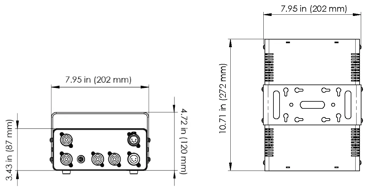
WEIGHT & DIMENSIONS (W/YOKE)
WIDTH ……………………………………………………………………………………………….. 8 IN / 202 MM
DEPTH …………………………………………………………………………………………… 10.7 IN / 272 MM
HEIGHT ……………………………………………………………………………………………. 7.3 IN / 186 MM
WEIGHT ………………………………………………………………………………………… 8.75 LB / 3.98 KG
POWER
AC POWER …………………………………………………………………………….. 90-240VAC, 50-60Hz
DC POWER ……………………………………………………………………. 24VCD, max. 6A per output
POWER CONSUMPTION …………………………………………………………………………… Up to 400W
CONTROL
AC POWER …………………………………………………………………………. 100s-240VAC, 50-60Hz
DC POWER ……………………………………………………………………. 24VCD, max. 6A per output
THERMAL
OPERATING TEMPERATURE ……………………………………………………………………. -20 TO +40 °C
COOLING ………………………………………………………………………………………. Passive / Active
CONTROL / PROGRAMMING
DMX IN / OUT …………………………………………………………………………………………. XLR 5-PIN
DMX CHANNELS …………………………………………………………………………………………….. 3-12
WARRANTY INFORMATION
WARRANTY ……………………………………………………………………….. 2-YEAR LIMITED WARRANTY
CONTACT INFORMATION
LOS ANGELES HEADQUARTERS
527 Park Avenue | San Fernando, CA 91340, USA
Tel: +1 818.899.8818 | Fax: +1 818.899.8813
[email protected]
TMB 24/7 TECH SUPPORT
US/Canada: +1.818.794.1286
Toll Free: 1.877.862.3833 (1.877.TMB.DUDE) UK: +44 (0)20.8574.9739
Toll Free: 0800.652.5418
[email protected]
LOS ANGELES +1 818.899.8818
LONDON +44 (0)20.8574.9700
NEW YORK +1 201.896.8600
BEIJING +86 10.8492.1587
CANADA +1 519.538.0888
A full service company providing technical support, customer service, and follow-up.
Providing products and services for the industrial, entertainment, installation, defense, broadcast, research, telecommunications, and signage industries. Servicing the global market from offices in Los Angeles, London, New York, Toronto, and Beijing.


