1/Safety Statements
Please read this user manual carefully before using the product. The user manual contains information on safe use, please keep it for future reference. Users can visit our website to learn about the update of the user manual.
1.1 General Safety 
- Please only use power adapter/source specially designed for this product or certified by your country/region (please refer to P3 for detailed power standards)
- Do not operate in humid environment;
- Do not operate in flammable and explosive environment;
- Please keep the product surface clean and dry.
1.2 Warnings
When using TS101,
- Please turn off the power when not in use or left unattended to prevent fire;
- After the power is turned on, the temperature of the soldering tip in operation will reach 50°C to 400°C (122°F to 752°F), so be careful to prevent burns;
- Do not soak TS101 in water or use it with wet hands to prevent electricity shock.
- Do not use DC and USB-C interface at the same time.
1.3 Precautions 
- TS101 controller is composed of precision components, dropping shall be avoided;
- After 5 minutes of continuous operation at full power above 350°C, or 40 minutes of continuous use, the controller temperature will reach above 50°C.
- For the first time using, due to the heating of the heating element,soldering tip may generate a light smoke, which is a normal phenomenon.
1.4 Liability Statements
Any special, indirect, incidental or subsequent damage or loss caused by the operation of the product that does not follow the contents of this manual (including but not limited to the operating conditions, warnings, precautions, instruction, etc.), the liability will belong to the user.
The user is responsible for any damage or loss caused by disassembling or modifying the product without permission.
Please keep this product in a safe place to prevent children from using this product without being supervised.
1.5 Operating Environment
| Working state | Non-working state | ||
| Temperature | +0°C~+50°C | -20°C~+60°C | |
Humidity | High temperature | 40°C~50°C 0%~60%RH | 40°C~60°C 5%~60%RH |
| Low temperature | 0°C~40°C 10%~90%RH | 0°C~40°C 5%~90%RH |
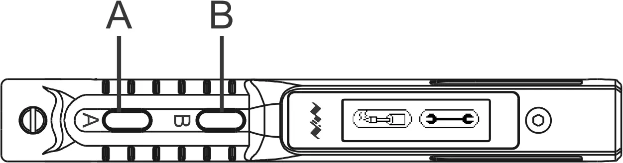
2/Product Overview
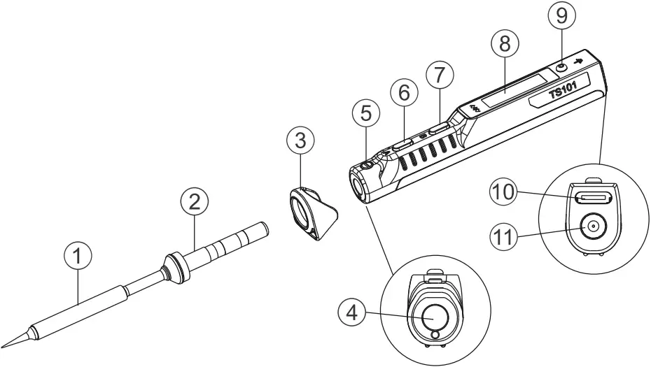
(1) Soldering Tip Heating End
(2) Soldering Tip Connection End
(3) Anti-slip Cap
(4) Soldering Tip Insertion End
(5) Ball screw
(6) Button A (heating, temperature adjustment)
(7) Button B (setting, temperature adjustment)
(8) OLED Screen
(9) Ground Screw
(10) USB TYPE-C interface
(11) DC5525 interface
2.2 Product Parameters
Screen | OLED (128*32 pixels) | |
USB interface | USB TYPE-C (for power source and firmware upgrade) | |
DC interface | DC5525 | |
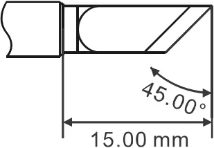
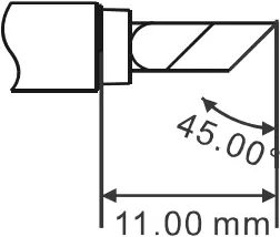
Size | Controller | L 98mm, φ13-16.5mm |
Soldering tip | φ5.5mm, L about 105mm (different types of soldering tips are slightly different) | |
Controller weight | 20g |
2.3 Working Parameters
| Working voltage and power | DC 9-24V 65W MAX / PD 45W MAX |
| Temperature control range | 50°C ~ 400°C |
| Temperature stability | ±3% |
| Soldering tip resistance to ground | <2Ω |
3/Power Source Selection
Smart Soldering Iron TS101 supports two power inputs: DC power source with DC5525 (9-24V) interface (including power adapter, power supply or battery pack, etc.) and PD power source with USB TYPE-C (9V and above) interface (including charger, power bank, etc.).
For DC power source, please check that the power source meets the following requirements:
Working Voltage | Working current | Power | The fastest time required to heat up from 30°C to 300°C |
| 9V | ≥1.0A | 9W | 95s |
12V | ≥1.3A | 16W | 43s |
| 16V | ≥1.8A | 30W | 22s |
19V | ≥2.2A | 40W | 15s |
| 24V | ≥2.8A | 65W | 9s |
For PD power source please select a standard PD power supply with the following parameter that supports more than 9V:
Working Voltage | Working current | Power | The fastest time required to heat up from 30°C to 300°C |
| 9V | ≥1.0A | 9W | 95s |
12V | ≥1.4A | 16W | 43s |
| 15V | ≥1.7A | 25W | 25s |
20V | ≥2.3A | 45W | 15s |
4/How to use
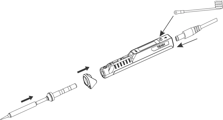
4.1 Install
1) Put the anti-slip cap into the front end of the soldering controller, and then insert the soldering tip into the controller;
2) Fix the ground wire with the ground screw;
3) Use a USB TYPE-C power cable or a DC power cable to connect the power source with TS101 (the two power supply methods cannot be used at the same time), turn on the power, and follow the instructions on the screen.
Note:
After the power is turned on, if TS101 shows No tip!”, it means the soldering tip is not firmly installed, please re-install the soldering tip.
Usage of anti-slip cap:
- When using the soldering iron, the anti-slip cap can prevent fingers from slipping;
- Acts as a simple stand to prevent the controller from rolling when placing the soldering iron;
- Hold the anti-slip cap and push it forward to help remove the soldering tip.
4.2 Factory Settings
Preset temperature unit | °C | |
| Preset temperature | T1 Temp | 300°C |
T2 Temp | 330°C | |
| T3 Temp | 350°C | |
Sleep temperature | 250°C | |
| Sleep time | 180S |
4.3 Basic Operations
4.3.1 Screen display
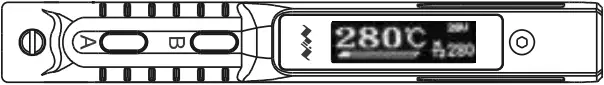
After the power is turned on, TS101 will firstly display the brand icon, personalized icon, product model and firmware version, then enters standby state and displays standby menu. If the temperature of soldering tip exceeds the safety temperature (40°C) in standby state, the screen will display the temperature as a warning to prevent burns.
Brand icon, not modifiable Personalized icon, modifiable;
the brand icon will be displayed by default if not modified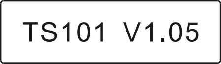
Product model and firmware version 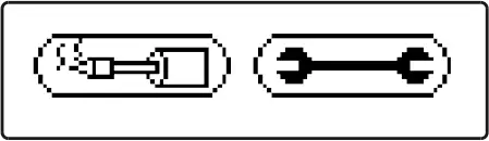
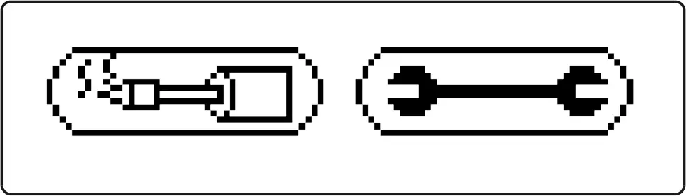
Heating and setting icons 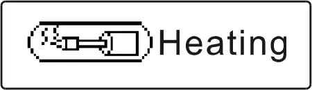
Heating icon 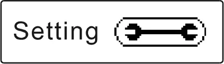
Setting icon 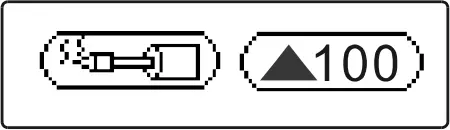
Warning icon of high temperature of soldering tip, the number indicates the current soldering tip temperature
4.3.2 Parameter Settings
1) In standby mode, press B to enter setting mode;
2) In setting mode, press A/B to select the setting item that needs to be modified, long press A to enter the modification state, press A/B to select the appropriate setting value and wait for 5 seconds after selection, the parameter is successfully modified and will automatically return to setting mode. Other settings can be modified in the same way;
3) After the setting is completed, long press B to save the modification and return to standby mode;
4) In standby state, long press A, TS101 screen will display the current internal resistance of the soldering tip as “Tip R:xx”;
5) In standby state, long press B, TS101 screen will display the current firmware version as “Ver:V1.xx”.
Note: In standby state, TS101 will enter the off screen state if it stay still for a long time. You can wake it up by shaking the controller to enter standby state.
Parameter Definitions: Default Setting 300 330 350 10 250 180 240 3 °C Right 380 DC 3500 OFF OFF 3Parameter Parameter Name Definition Parameter Range T1 Temp Preset temperature 1 System preset working temperature 1 °C: 50~400,
°F: 122~752T2 Temp Preset temperature 2 System preset working temperature 2 T3 Temp Preset temperature 3 System preset working temperature 3 Temp Step Temperature step The stepping of each button operation when adjusting temperature 1~25 Sleep Temp Sleep temperature(1) Standby temperature in sleep mode, it is recommended to set the value not higher than working temperature °C: 50~400,
°F: 122~752Sleep Time Sleep Time 1. Time needed to enter sleep mode from working mode when controller stays still; 2. Time needed to enter off screen state from standby mode. 60~999,
unit: secondIdle Time Idle time Time needed to enter from standby mode to sleep mode 60~999,
unit: secondBacklight Screen brightness LED Screen brightness 1 to 10; the larger the number, the brighter the screen TempUnit Temperature unit Temperature display unit °C: Celsius,
°F: FahrenheitDisplayDir Display direction Screen display direction; in different modes, the screen display direction will be reversed, yet the button function will remain unchanged Right: right hand mode,
Left: left hand modeBoostTemp Boost temperature Preset working temperature for boost mode (by holding Button A in working mode) °C: 50~400,
°F: 122~752PowerSrc DC power source Types of DC power source DC: DC power adapter, 3S~6S: series battery pack MinVolt Unit minimum voltage Minimum working voltage per cell when powered by a series battery pack 3300~4000,
unit: mVLowCurrent Low current wakeup (2) In TS101 standby mode, this feature can keep power bank in active state OFF, ON PDPwMax PD power limit Maximum power when using PD power source 0: OFF,
18~45:18~45,
unit: wattMsenUnit Sensitivity Adjust the sensitivity of the internal sensor, the higher the value, the more sensitive 1~5 TempCalib Temperature calibration Calibrate the soldering tip temperature; let the soldering tip cool to room temperature before calibrating Restore Reset (3) Reset
Note:(1) The Low current wakeup function is only valid when connected with a PD power source (such as a PD power bank). After the function is turned on, the soldering tip may be warm in standby mode, so beware of burns; (2)The setting value of Sleep Time can not only control the time from the working mode to the sleep state, but also the time from standby mode to off screen state; (3)Restoring the factory settings will restore the temperature calibration parameters of the soldering iron to the default values.
4.3.3 Heating Operation
- Heating operation: In standby state, press A, TS101 will enter heating working mode, after the temperature is heated to the preset working temperature, TS101 will automatically maintain a constant temperature;
- Boost operation: in heating working state, hold A, TS101 will enter boost heating mode, and the temperature of the soldering tip will rise to the boost heating temperature and maintain a constant temperature. When Button A is released, the temperature will drop back to stay in preset working temperature;
- Long press B in heating mode to return to standby mode.
Note: If the power source voltage is too low, the screen will show “Low volt!”, please replace the power source (please refer to P3 for detailed power source standards).
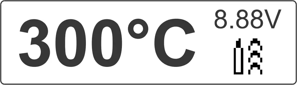
Interface icon description: Screen Area A B C D E F G![]()
Display Content Definition Current temperature value and unit Current temperature of the soldering tip ![]()
TS101 is in boost mode No display TS101 is in normal working state Voltage value and unit Current power source voltage Solid line Instant working power bar, the length of the power bar indicates the ratio of the current instant power to the maximum power M TS101 is moving No display TS101 is still T1/T2/T3 Preset temperature T1-T3 zZ TS101 is in sleep mode Numerical value Current preset temperature
4.3.4 Temperature Adjustment
TS101 has two temperature adjustment methods: select preset temperature or directly adjust temperature.
1) Select preset temperature: in standby state, press A to select preset temperature T1/T2/T3, after selection, TS101 will heat up to the selected preset temperature and maintain a constant temperature;
2) Direct temperature adjustment: in heating state, press B to enter “Work Temp” menu of the working temperature setting, and press NB to adjust temperature (long press A/B for quick adjustment). The setting will be automatically saved and returned to heating mode after 5 seconds of no operation, heated to the set temperature and then keep in the temperature (this modification is valid for one time setting, and will not be saved after power off).
4.3.5 Sleep and Standby Mode

In working mode, if TS101 stays still for 180 seconds (factory default setting, which can be modified by “Sleep Time”), it will enter sleep mode, the “zZ” symbol will appear on the screen, and the soldering tip will cool down to sleep temperature (can be adjusted by the “Sleep Temp”).
When movement is detected, TS101 will exit the sleep mode and automatically return to working mode, and the soldering tip will heat up to the working temperature before sleep mode.
When left still in sleep mode for 240 seconds (factory default setting, can be modified by “Idle Time”), TS101 will return to standby mode. Another 180 seconds in standby mode (factory default setting, can be modified by “Sleep Time”), and the screen of TS101 will turn off.
4.4 Configuration File
1) Use a USB TYPE-C data cable to connect TS101 to the computer, a virtual disk will appear on the computer, and TS101 will enter USB mode and display “CONFIG” on screen;
2) Open the CONFIG.TXT file in the virtual disk, and modify the setting parameters (the parameter setting value should be within the adjustable range);
3) After the setting parameters are saved, they will be updated to TS101 immediately.
The parameter setting ranges are as follows:
| Parameter | Parameter Name | Range | Default |
| T1_Temp | Preset working temperature 1 | °C: 50~400, °F: 122~752 | 300 |
| T2_Temp | Preset working temperature 2 | °C: 50~400, °F: 122~752 | 330 |
| T3_Temp | Preset working temperature 3 | °C: 50~400, °F: 122~752 | 350 |
| SlpTemp | Sleep temperature | °C: 50~400, °F: 122~752 | 250 |
| BoostTemp | Boost temperature | °C: 50~400, °F: 122~752 | 380 |
| SlpTime | Sleep time | 60~999 (unit: second) | 180 |
| IdleTime | Idle time | 60~999 (unit: second) | 240 |
| Backlight | Screen brightness | 1~10 | 3 |
| TempUnit | Temperature unit | 0: Celsius, 1: Fahrenheit | 0 |
| DisplayDir | Display direction | 1: Right hand mode, 2: Left hand mode | 1 |
| TempStep | Temperature step | 1~25 | 10 |
| PowerSrc | Types of DC power source | 0: DC power adapter, 3~6: 3S~6S series battery pack | 0 |
| MinVolt | Unit minimum voltage | 3300~4000 (unit: millivolt) | 3500 |
| LowCurrent | Low current wakeup | 0: OFF, 1: ON | 0 |
| PDPwMax | PD power limit | 0: OFF, 18~45: 18~45 (unit: watt) | 0 |
| MsenUnit | Sensitivity | 1~5, the higher the value, the more sensitive | 3 |
5/Soldering Tips
5.1 Replace A Soldering Tip
1) Please replace the soldering tip after power off;
2) Pull out the original soldering tip and reinsert another soldering tip;
3) Power on again. If TS101 shows “No tip!”, it means that the soldering tip is not firmly installed, please reinsert the soldering tip.
Note: The soldering tip insertion end of TS101 controller uses a ball screw to fix the soldering tip, and the tightness of the screw has been adjusted before leaving the factory. If necessary, users can adjust it by themselves.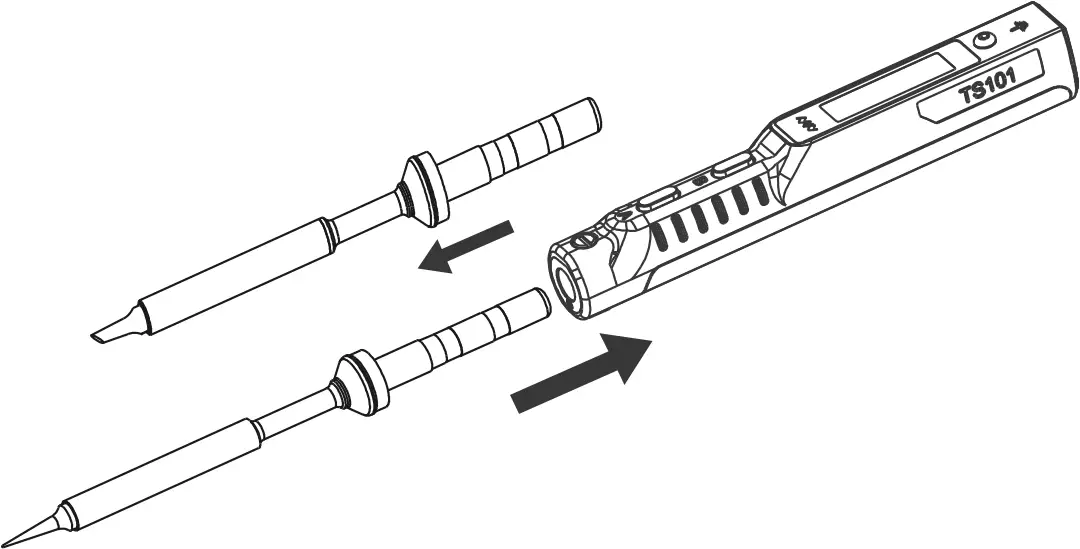
5.2 Choosing A Soldering Tip
TS101 uses the same soldering tips with TS100 Mini Soldering Iron. Choosing a right soldering tip can make your job more efficient.
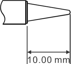
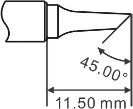
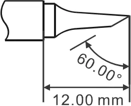
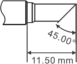
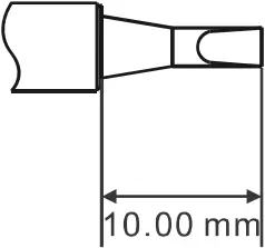
TS-B2 TS-BC2 TS-C1 TS-C4 TS-D24
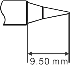
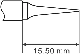
TS-I TS-ILS TS-K TS-KU
5.3 Maintenance of Soldering Tips
1) When not in use for a long time, it is recommended that the soldering tip be properly tinned to prevent oxidation;
2) Do not let the soldering tip be heated at a high temperature for a long time to avoid dry burning;
3) When soldering, do not apply too much pressure on the soldering tip to rub the solder joints to avoid damage to the soldering tip;
4) Never use rough materials or files to clean the tip of the soldering iron;
5) If the surface of the soldering tip has been oxidized and does not stick to tin, User can carefully rub it with 600-800 mesh gold steel emery cloth and clean it with ethyl propanol or an equivalent solution as needed, then heat to 200 °C, and dip tin immediately to prevent oxidation;
6) Do not use chlorine or acid-rich flux, only use synthetic resin or activated resin flux.
6/FAQ
1. Check power source and cable;
2. Check if TS101 can enter DFU mode after connecting to the computer and read the virtual disk.
1. Is the soldering tip used for the first time or stored in a humid environment?
When the soldering tip is fully heated, the temperature can be maintained;
2. Whether the soldering tip has been installed correctly;
3. Whether the power cable is in poor contact.
1. Whether the power supply is plugged in and powered on normally;
2. Whether the power parameters meet the usage requirements.
1. Whether the soldering tip has been installed correctly;
2. Whether the soldering tip is in poor contact;
3. Long press A to check the internal resistance of the soldering tip.
1. Whether the temperature of the soldering tip exceeds 400°C;
2. Whether the soldering tip is not properly tinned;
3. Whether there is a lack of flux or using solder with low purity or low tin;
4. Whether you have ever wiped the soldering tip with a dry sponge or shredded with high sulfur content or dryness?
5. Whether the tip has come into contact with organic substances such as plastics, silicon (silicon) grease or other chemicals.
Set the “LowCurrent” menu option as “ON”.
7/Service and Upgrade
7.1 After-sales Service
The soldering iron controller has a one-year free warranty service in the case of non-artificial damage. Please contact the dealer for warranty service. Soldering tips are consumables, if there is no quality problem once used they will not be returned.
7.2 Customize Personalized Icons
1) Prepare a 128*32 pixel monochrome BMP image, and set the file name as logoin.bmp;
2) Use a USB TYPE-C data cable to connect the controller to the computer and enter the virtual disk;
3) Copy the prepared image to the root directory of the virtual disk, disconnect to complete the update.
7.3 Firmware Update
1) Visit www.miniware.com.cn and download the applicable soldering iron firmware to the computer;
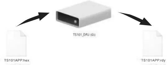
2) Hold Button A of TS101 and connect it to the computer via a USB TYPE-C date cable. TS101 enters DFU mode, the screen displays “DFU: 1.03”, and a virtual disk appears on the computer;
3) Copy the prepared .hex firmware to the root directory of the disk. When the firmware suffix changes from .hex to .rdy, disconnect to complete firmware upgrade.
8/Legal Statements

This device is complied with the regulation in the 15th part of FCC regulation. Operation is subject to the following two conditions:
(1) This device may not cause harmful interference.
(2) This device must accept any interference received, including the interference that may cause undesired operation.

The CE mark is a registered trademark of European Community.
This CE mark shows that the product complies with all the relevant European Legal Directives.

UKCA (United Kingdom Conformity Assessed) mark is a certification mark for UK conformity.
This device complies with the standard testing and certification under British regulations required for electrical and electronic products to enter the British market.

This product contains batteries and/or recyclable electronic parts. Please do not dispose of the product together with household garbage. Please handle it according to your local laws and regulations.


