![]() Inch Diameter Head Drive Pins
Inch Diameter Head Drive Pins
Instruction Manual’
GENERAL INFORMATION
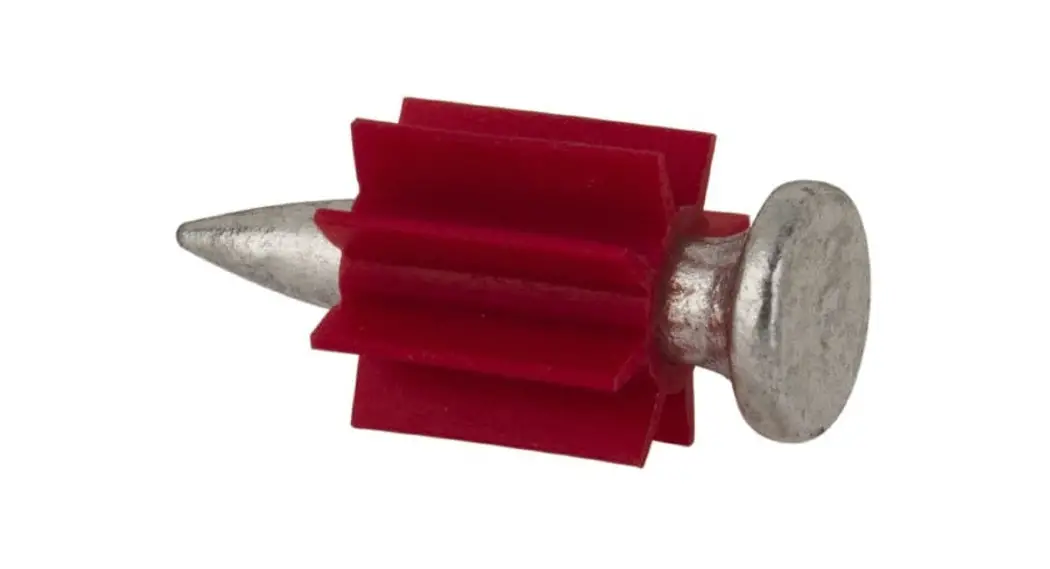
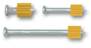
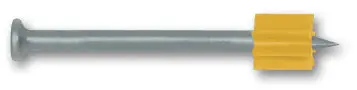
0.300″ HEAD DRIVE PINS
Standard Flat Head Fasteners
INTRODUCTION
Drive pins with a 0.300″ diameter head are designed for permanently fastening a fixture to concrete, concrete over steel deck, concrete masonry walls and A36 or A572 / A992 structural steel. The fasteners are manufactured with a 0.145″ diameter shank in various lengths. Knurled shank designs are available for installations in thick steel base materials. A plastic flute is mounted on the pin shank to retain the drive pin in the barrel of the tool and provide guidance during the driving operation. The fasteners are also available in with a mechanically galvanized (MG) coating for use in treated lumber.
GENERAL APPLICATIONS AND USES
- Attaching light gauge steel to concrete, concrete over steel deck, concrete masonry or steel
- Attaching wood members to concrete, concrete masonry or steel
- Attaching accessories, fixtures and components to concrete, concrete over steel deck, concrete masonry or steel
- Sill plate anchorage
APPROVALS AND LISTINGS
- International Code Council, Evaluation Service (ICC-ES), ESr-2024
- Code compliant with the International Building Code/International residential Code: 2018 IBC/IrC, 2015 IBC/IrC, 2012 IBC/IrC, and 2009 IBC/IrC
- Tested in accordance with ASTM E1190 and ICC-ES AC70 for use in concrete, concrete over steel deck, concrete masonry and steel
GUIDE SPECIFICATION
- CSI Divisions: 03 15 00 – Concrete Accessories, 05 05 23 – Metal Fastenings, 06 05 23 – wood,Plastic and Composite Fastenings, 09 22 16.23 – Fasteners.Power-driven fasteners shall be 0.300″ head drive pins as supplied by DEwALT, Towson, MD. Fasteners shall be installed in accordance with published instructions and the Authority Having Jurisdiction.
SUITABLE BASE MATERIALS
- Normal-weight concrete
- Lightweight concrete
- Concrete over steel deck
- Grouted concrete masonry (CMU)
- Hollow concrete masonry (CMU)
- Steel
FASTENER SIZE RANGE
- 1/2″ length through 3″ length
CODE LISTED
ICC-ES ESR-2024
CONCRETE, MASONRY, STEEL.
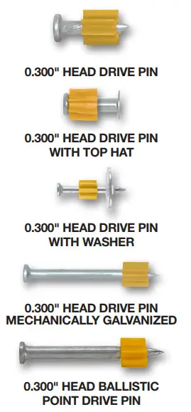
SELECTION GUIDE
| Pin / Fastener Description | Dimensions | Base Material | DEWALT Tools | Approvals & Listings | ||||||||||
| Shank Diameter | Shank Length | Concrete | Lightweight Concrete | Concrete over Steel Deck | Concrete Masonry (CMU) | Steel | P1000 /T1000 | P2201 | P35s | P3500 / PA3500 | Sniper | DFD270 | ||
| 0.300″ Head Pin (including MG pins) | 0.145″ | 1/2″ to 1-1/2″ | • | • | • | • | • | • | • | • | • | • | • | ICC-ES ESR-2024 |
| 0.145″ | 2″ to 3″ | • | • | • | • | • | • | • | • | • | ICC-ES ESR-2024 | |||
| 0.300″ Head Pin with Top Hat | 0.145″ | 1/2″ to 1″ | • | • | • | • | • | • | • | • | • | • | • | ICC-ES ESR-2024 |
| 0.300″ Head Pin with Washer including MG pins) | 0.145″ | 3/4″ to 1-1/2″ | • | • | • | • | • | • | • | • | • | • | • | ICC-ES ESR-2024 |
| 0.145″ | 2″ to 3″ | • | • | • | • | • | • | • | • | • | ICC-ES ESR-2024 | |||
| 0.300″ Head Ballistic Point Pin | 0.181/0.150″ | 1-7/8″ | • | • | • | • | • | • | • | • | • | ICC-ES ESR-2024 | ||
| • Suitable • May be Suitable | ||||||||||||||
| MG = Mechanical Galvanized | ||||||||||||||
PERFORMANCE DATA
Allowable Load Capacities for Powder Actuated Fasteners in Normal-Weight Concrete1,2,3,4,5,6
| Fastener Description | Minimum Embed. Depth in. (mm) | Minimum Concrete Compressive Strength (f’c) | |||||||
| 2,000psi | 2,500psi | 3,000psi | 4,000psi | ||||||
| Tension lbs. (kN) | Shear lbs. (kN) | Tension lbs. (kN) | Shear lbs. (kN) | Tension lbs. (kN) | Shear lbs. (kN) | Tension lbs. (kN) | Shear lbs. (kN) | ||
| 0.300″ Head Drive Pin (0.145″ Shank) | 5/8 (15.9) | 25 (0.1) | 45 (0.2) | 80 (0.4) | 150 (0.7) | 85 (0.4) | 150 (0.7) | 85 (0.4) | 150 (0.7) |
| 3/4 (19.1) | 60 (0.3) | 95 (0.4) | 85 (0.4) | 195 (0.9 | 90 (0.4) | 195 (0.9) | 90 (0.4) | 195 (0.9) | |
| 1 (25.4) | 100 (0.4) | 140 (0.6) | 145 (0.6) | 400 (1.8) | 145 (0.6) | 400 (1.8) | 145 (0.6) | 400 (1.8) | |
| 1-1/4 (31.8) | 110 (0.5) | 155 (0.7) | 305 (1.4) | 495 (2.2) | 305 (1.4) | 495 (2.2) | 305 (1.4) | 495 (2.2) | |
| 1-1/2 (38.1) | 115 (0.5) | 175 (0.8) | 305 (1.4) | 495 (2.2) | 465 (2.1) | 505 (2.2) | 465 (2.1) | 505 (2.2) | |
1. Fasteners must not be driven until the concrete has reached the minimum designated compressive strength. Linear interpolation may be used to determine allowable loads for intermediate compressive strengths. | |||||||||
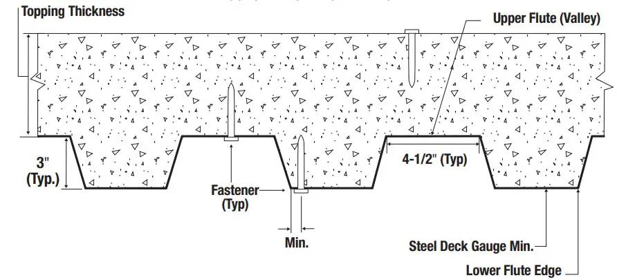
Allowable Load Capacities for Powder Actuated Fasteners in Lightweight Concrete and Lightweight Concrete over Steel Deck1,2,3,8
| Fastener Description | Minimum Embed. Depth in. (mm) | Minimum Concrete Compressive Strength, f ‘c = 3,000 psi | |||||
| Directly into Concrete4,5 | Through Soffit of Steel Deck Into Concrete (3-inch Deep Profile) | ||||||
| Upper Flute6,7 | Lower Flute6,7 | ||||||
| Tension | Shear | Tension | Shear | Tension | Shear | ||
| Allowable lbs (kN) | Allowable lbs (kN) | Allowable lbs (kN) | Allowable lbs (kN) | Allowable lbs (kN) | Allowable lbs (kN) | ||
| 0.300″ Head Drive Pin (0.145″ Shank) | 3/4 (19) | 70 (0.3) | 70 (0.3) | 165 (0.7) | 280 (1.3) | 95 (0.4) | 290 (1.3) |
| 7/8 (22) | 135 (0.6) | 145 (0.6) | 165 (0.7) | 280 (1.3) | 165 (0.7) | 290 (1.3) | |
| 1 (25) | 200 (0.9) | 215 (1.0) | 175 (0.8) | 290 (1.3) | 165 (0.7) | 290 (1.3) | |
| 1-1/4 (32) | 250 (1.1) | 305 (1.4) | 280 (1.2) | 340 (1.5) | 190 (0.8) | 340 (1.5) | |
| 1-1/2 (38) | 340 (1.5) | 375 (1.7) | 280 (1.2) | 380 (1.7) | 235 (1.0) | 380 (1.7) | |
1. Fasteners must not be driven until the concrete has reached the minimum designated compressive strength. For a concrete compressive strength of 4,000 psi, the tabulated allowable loads may be increased by 12 percent. Fasteners may also be installed in 2,500 psi concrete provided the allowable loads are reduced by 11 percent. | |||||||
Allowable Load Capacities for Powder Actuated Fasteners used to Install Wood Sill Plates into Normal-Weight Concrete1,2,3,4,5,6,7,8,9,10
| Fastener Description | Minimum Embedment Depth in. (mm) | Minimum Concrete Compressive Strength, f ‘c = 2,000 psi | ||
| Tension | Load Perpendicular to Edge | Load Parallel to Edge | ||
| Shear | Shear | |||
| Allowable lbs. (kN) | Allowable lbs. (kN) | Allowable lbs. (kN) | ||
| 0.300″ Head Drive Pin (0.145″ Shank) | 1-1/2 (38) | 125 (0.6) | 150 (0.7) | 230| (1.0) |
1. Fasteners must not be driven until the concrete has reached the minimum designated compressive strength. | ||||
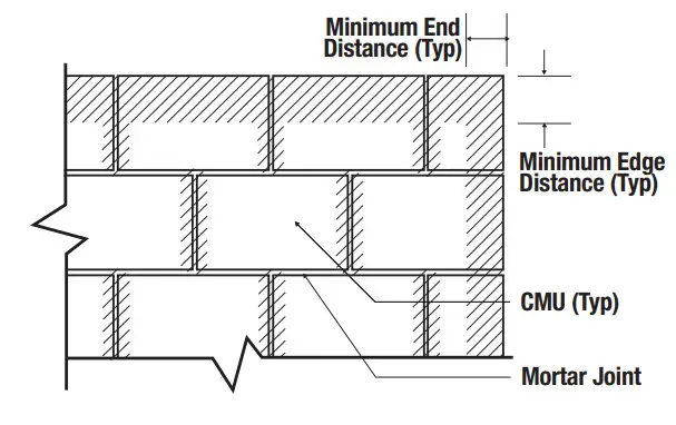
Allowable Load Capacities for Powder Actuated Fasteners in Concrete Masonry (CMU)1,2,3,9,10,11
| Fastener Description | Min. Embed. Depth in. (mm) | Minimum Masonry Compressive Strength, f ‘c = 1,500 psi | |||||||
| Hollow CMU4,5 | Grout-filled Concrete Masonry6,7,8 | ||||||||
| Cell Face | Cell Face | Mortar Joint | Top of Grouted Wall | ||||||
| Tension | Shear | Tension | Shear | Tension | Shear | Tension | Shear | ||
| Allowable lbs (kN) | Allowable lbs (kN) | Allowable lbs (kN) | Allowable lbs (kN) | Allowable lbs (kN) | Allowable lbs (kN) | Allowable lbs (kN) | Allowable lbs (kN) | ||
| 0.300″ Head Drive Pin (0.145″ Shank) | 1| (25) | 35 (0.2) | 95 (0.4) | 150 (0.7) | 155(0.7) | 140 (0.6) | 170 (0.8) | 45 (0.3) | 115 (0.5) |
1. Fasteners must not be driven until the masonry has reached the minimum designated compressive strength. Concrete masonry must be minimum 8-inch wide, minimum Grade N, Type II, lightweight, medium-weight or normal-weight units conforming to ASTM C90. Mortar must be minimum Type N complying with ASTM C270. Grout must be coarse grout complying with ASTM C476. | |||||||||
Allowable Load Capacities for Powder Actuated Fasteners in ASTM A36 Steel1,2,3,5,6
|
Fastener Description | Nominal Steel Thickness (inch) | |||||||||
| 1/8 | 3/16 | 1/4 | 3/8 | 1/2 (4) | ||||||
| Tension lbs. (kN) | Shear lbs. (kN) | Tension lbs. (kN) | Shear lbs. (kN) | Tension lbs. (kN) | Shear lbs. (kN) | Tension lbs. (kN) | Shear lbs. (kN) | Tension lbs. (kN) | Shear lbs. (kN) | |
| 0.300″ Head Drive Pin (0.145″ Knurled Shank) | 220 (1.0) | 200 (0.9) | 340 (1.5) | 610 (2.7) | 445 (2.0) | 560 (2.5) | 520 (2.3) | 605 (2.7) | 490 (2.2) | 575 (2.6) |
| 0.300″ Head Drive Pin (0.145″ Smooth Shank) | 170 (0.8) | 265 (1.2) | 355 (1.6) | 565 (2.5) | 410 (1.8) | 560 (2.5) | 465 (2.1) | 390 (1.7) | 390 (1.7) | 520 (2.3) |
1.Fastener capacities are based on the base steel with a minimum yield strength (Fy) of 36 ksi and a minimum ultimate tensile strength (Fu) of 58 ksi. The pointed portion of the fastener must penetrate the steel member unless otherwise noted. | ||||||||||
Nominal and Allowable Pull-Over Strengths for Light Gauge Steel Framing with Power-Driven Fasteners1,2,3
| Fastener Description | Shank Diameter | Minimum Thickness of Steel or Framing Member | |||||||||
| 16 Gauge | 18 Gauge | 20 Gauge | 22 Gauge | 25 Gauge | |||||||
| Nominal (lbs) | Allowable (lbs) | Nominal (lbs) | Allowable (lbs) | Nominal (lbs) | Allowable (lbs) | Nominal (lbs) | Allowable (lbs) | Nominal (lbs) | Allowable (lbs) | ||
| 0.300″ Head Drive Pin with 7/8″ or 1″ washer | 0.145″ | 3,120 | 1,040 | 2,495 | 830 | 1,875 | 625 | 1,560 | 520 | 1,090 | 365 |
| 0.300″ Head Drive Pin | 0.145″ | 1,560 | 520 | 1,250 | 415 | 935 | 310 | 780 | 260 | 545 | 180 |
| 1.Tabulated pull-over strengths were calculated in accordance with ICC-ES AC70 and AISI S100-16. Allowable load values are based on a safety factor of 3.0. 2. Allowable pullover capacities of sheet steel or framing member should be compared to the fastener tensile capacity in concrete, masonry or steel to determine the controlling resistance load. 3 Steel or framing member with tensile strength of 58 ksi assumed for calculating tabulated values. | |||||||||||
OPDERING INFORMATION
0.300″ Diameter Head Drive Pins
| Cat. No. | Shank Length | Shank Diameter | Ctn Qty | Mstr Qty |
| 50012-PWR | 1/2″ (K) | 0.145″ | 100 | 5,000 |
| 50016-PWR | 5/8″ (K) | 0.145″ | 100 | 5,000 |
| 50022-PWR | 3/4″ | 0.145″ | 100 | 5,000 |
| 50023-PWR | 3/4″ (black) | 0.145″ | 100 | 5,000 |
| 50026-PWR | 1″ | 0.145″ | 100 | 5,000 |
| 50032-PWR | 1-1/4″ | 0.145″ | 100 | 1,000 |
| 50034-PWR | 1-1/2″ | 0.145″ | 100 | 1,000 |
| 50038-PWR | 2″ | 0.145″ | 100 | 1,000 |
| 50040-PWR | 2-1/4″ | 0.145″ | 100 | 1,000 |
| 50044-PWR | 2-1/2″ | 0.145″ | 100 | 1,000 |
| 50048-PWR | 3″ | 0.145″ | 100 | 1,000 |
| (K) = knurled Black pins have a black coating instead of zinc plating. | ||||
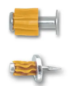
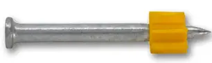
0.300″ Diameter Head Drive Pins with Top Hat
| Cat. No. | Shank Length | Shank Diameter | Ctn Qty | Mstr Qty |
| 50136-PWR | 1/2″ (K) | 0.145″ | 100 | 5,000 |
| 50138-PWR | 5/8″ (K) | 0.145″ | 100 | 5,000 |
| 50140-PWR | 3/4″ | 0.145″ | 100 | 5,000 |
| 50144-PWR | 1″ | 0.145″ | 100 | 5,000 |
| (K) = knurled | ||||
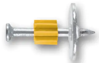
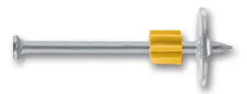
0.300″ Diameter Head Drive Pins with 3/4″ Washer
ORDERING INFORMATION
| Cat. No. | Shank Length | Shank Diameter | Ctn Qty | Mstr Qty |
| 50090-PWR | 1″ | 0.145″ | 100 | 1,000 |
| 50092-PWR | 1-1/4″ | 0.145″ | 100 | 1,000 |
| 50094-PWR | 1-1/2″ | 0.145″ | 100 | 1,000 |
| 50096-PWR | 2″ | 0.145″ | 100 | 1,000 |
| 50098-PWR | 2-1/2″ | 0.145″ | 100 | 1,000 |
| 50100-PWR | 3″ | 0.145″ | 100 | 1,000 |
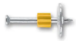
0.300″ Diameter Head Drive Pins with 1″ Washer
| Cat. No. | Shank Length | Shank Diameter | Ctn Qty | Mstr Qty |
| 50108-PWR | 1-1/4″ | 0.145″ | 100 | 1,000 |
| 50110-PWR | 1-1/2″ | 0.145″ | 100 | 1,000 |
| 50112-PWR | 2″ | 0.145″ | 100 | 1,000 |
| 50114-PWR | 2-1/2″ | 0.145″ | 100 | 1,000 |
| 50116-PWR | 3″ | 0.145″ | 100 | 1,000 |
| 50120-PWR* | 3″ | 0.145″ | 100 | 1,000 |
| *Square Washer | ||||
0.300″ Diameter Head Drive Pins (Mechanically Galvanized)
| Cat. No. | Shank Length | Shank Dia. | Ctn Qty | Mstr Qty |
| 50034MG-PWR | 1-1/2″ | 0.145″ | 1,000 | 5,000 |
| 50038MG-PWR | 2″ | 0.145″ | 1,000 | 5,000 |
| 50045MG-PWR | 2-1/2″ | 0.145″ | 1,000 | 5,000 |
| 50047MG-PWR | 3″ | 0.145″ | 1,000 | 5,000 |
Mechanically Galvanized (MG) fasteners meet ASTM B695, Class 55. Fasteners are designed for fastening through pressure treated lumber. The fasteners are available with a round washer for increased pullover resistance. | ||||
0.300″ Diameter Head Drive Pins with 1″ Washer (Mechanically Galvanized)
| Cat. No. | Shank Length | Shank Dia. | Ctn Qty | Mstr Qty |
| 50110MG-PWR | 1-1/2″ | 0.145″ | 1,000 | 5,000 |
| 50112MG-PWR | 2″ | 0.145″ | 1,000 | 5,000 |
| 50113MG-PWR | 2-1/2″ | 0.145″ | 1,000 | 5,000 |
| 50115MG-PWR | 3″ | 0.145″ | 1,000 | 5,000 |
| Mechanically Galvanized (MG) fasteners meet ASTM B695, Class 55. Fasteners are designed for fastening through pressure treated lumber. The fasteners are available with a round washer for increased pullover resistance. | ||||
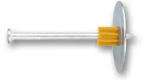
0.300″ Diameter Head Drive Pins with 1-7/8″ Insulation Washer
| Cat. No. | Shank Length | Shank Dia. | Ctn Qty | Mstr Qty |
| 50122-PWR | 1-1/2″ | 0.145″ | 100 | 1,000 |
| 50126-PWR | 2-1/2″ | 0.145″ | 100 | 1,000 |
0.300″ Diameter Head Ballistic Point Drive Pins
| Cat. No. | Shank Length | Shank Dia. | Ctn Qty | Mstr Qty |
| 50057-PWR | 1-7/8″ | 0.181/0.150″ | 100 | 1,000 |
| Ballistic point pins have a zinc plating. | ||||
![]() TECHNICAL GUIDE
TECHNICAL GUIDE
POWDER ACTUATED ©2022 DEWALT – REV. A
www.DeWALT.Com


