ENGEL MT60F-U1-C AC DC Combi Fridge Freezer

SPECIFICATIONS
Specifications Table
| MODEL | MT60F-U1 | MT80F-U1-S | MT60F-U1-C | |
| STORAGE VOLUME | liter | 60 | 80 | 25 (Freezing side) 32 (Refrigerator side) |
| EXTERNAL DIMENSIONS W×D×H | in | 31.6×20.5×17.4 | 31.6×20.5×22.1 | 31.6×20.5×17.4 |
| mm | 802×520×441 | 802×520×561 | 802×520×441 | |
| INTERNAL DIMENSIONS W×D×H | in | 20.4×14.9×12.4 | 20.2×16.1×14.8 | 8×15×12.5 (FREEZER) 10×15.5×12.5 (FRIDGE) |
| mm | 517×378×315 | 514×410×375 | 205×378×315 (FREEZER) 260×400×315 (FRIDGE) | |
| OUTER ENCLOSURE | DOOR | Cold rollomg steel sheet. (Melamine baking finish) | ||
| CABINET | ||||
| INNER ENCLOSURE | DOOR | ABS resin | ||
| CABINET | ||||
| HEAT INSULATOR | DOOR | Foamed Polyurethane | ||
| CABINET | ||||
| INPUT VOLTAGE | AC | 120V | ||
| DC | 12V / 24V | |||
| RATED AMPERAGE | AC | 1.2A | ||
| DC | 4.2A / 2.1A | |||
| COMPRESSOR RATING | AC 16 V, 3A 48W | |||
| REFRIGERANT | Dichlorodifluoromethane (HFC-134a) | |||
| AVERAGE INNER TEMPERATURE (at ambient temp 30℃) | 7℃±3℃ (with dial notch at ‘1’) | |||
| TEMPERATURE CONTROL DIAL AT ‘5’ OR ABOVE (at ambient temp 30℃) | lees than −18 ℃ | <Refrigerator side> must be MAX5℃ MIN- | ||
| <Freezing side> lees than −18 ℃ | ||||
| TEMPERATURE CONTROL | Digital temperature control with electronic thermostat | |||
| WEIGHT | LBS. | 72 | 86 | 73 |
| Kg | 32 | 39 | 33 | |
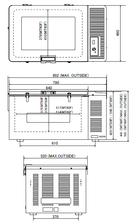
Dimensions (MT60F-U1 / MT80F-U1-S)
- Tolerance is omitted

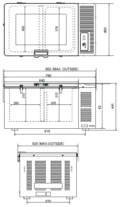
Dimensions (MT60F-U1-C)
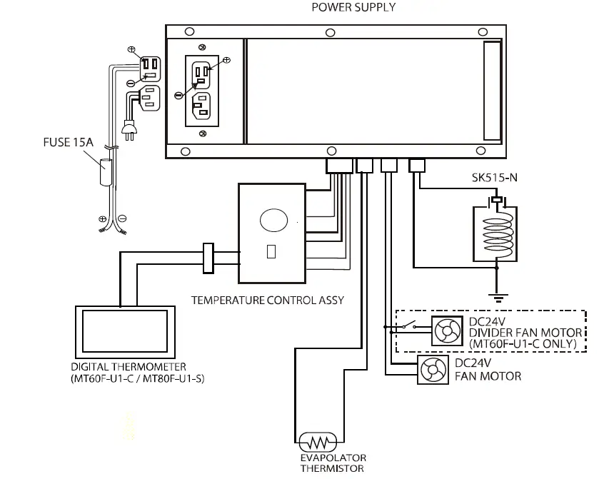
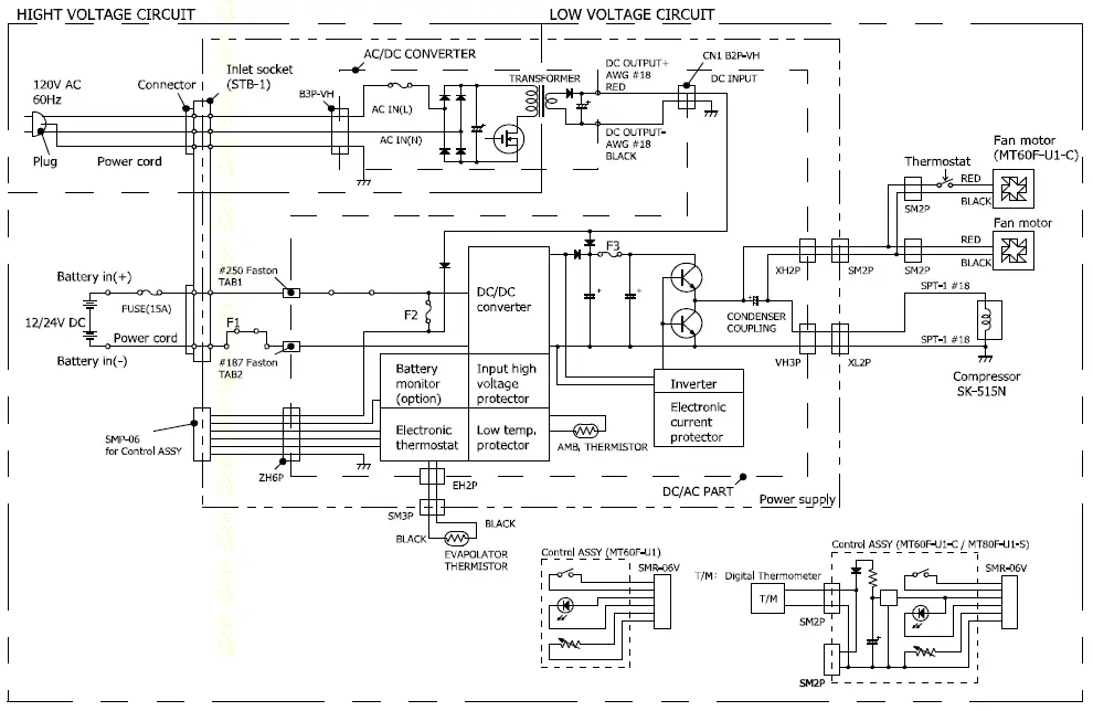
WIRING DIAGRAM
- Block Diagrams

- Wiring Diagrams
 PARTS NAME
 PARTS NAME
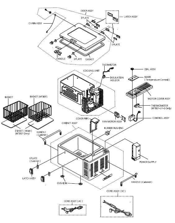
Parts name (MT60F-U1 / MT80F-U1-S)
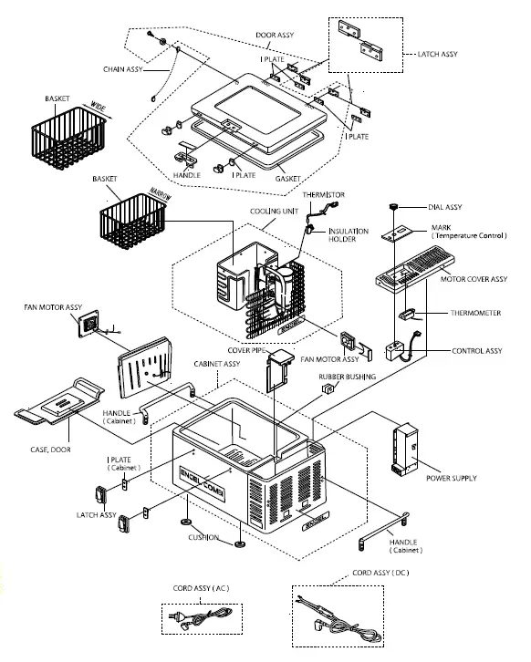
Parts name (MT60F-U1-C)
INSTALLING A REFRIGERATOR
How to Install the Refrigerator.
- Your shockproof fridge is best installed on a solid surface.
- Be sure your fridge is not placed near a gas stove, heater or other heat-generating appliances.
- Adequate ventilation and a suitable distance from each wall (at least 150mm or more) is necessary for maximum cooling efficiency and minimum electric current consumption for “free-standing use” (see Fig. shown below).
- Avoid installing your fridge close to the kitchen sink or faucet.
- If you use the fridge under the counter or in the fixing box, please note the following air ventilation conditions.
- Make vent opening both under fridge or bottom and above fridge top cover.
- The vent opening size must be larger than 160㎠ for each opening (the more air circulation over the condenser, the more efficiently fridge will operate).

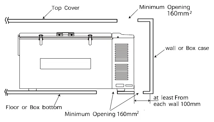
WORK TIPS
Failure to provide the necessary venting will result in poor refrigeration, continuous compressor operation, accelerated battery discharge and sometimes shorten the life of fridge.
TROUBLESHOOTING
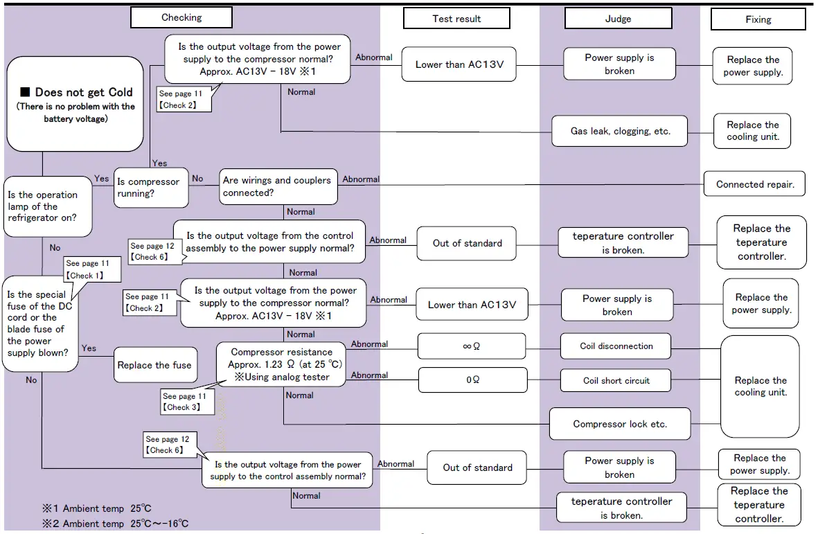
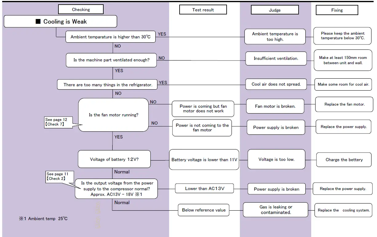
CHECKING POINT & METHOD
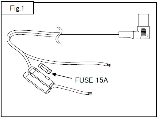
【Check 1】 Fuse (Fig.1)
- Check the resistance of fuse by tester.
Test result Assessment 0Ω Normal ∞Ω Broken 
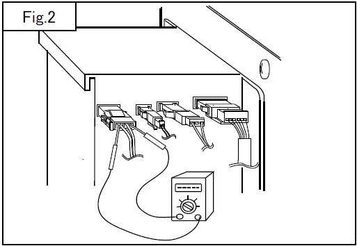
- 【Check 2】 Input Voltage of the Compressor (Fig.2)
- Checking point
- Check at 2 pin coupler of Inverter (Fig.2) or at input terminals of the compressor. ( Should be checked when the compressor is connected )
Test result Assessment Approx. AC13~18V Normal AC 0 V Inverter is broken Approx. AC13V or lower Compressor is locked 
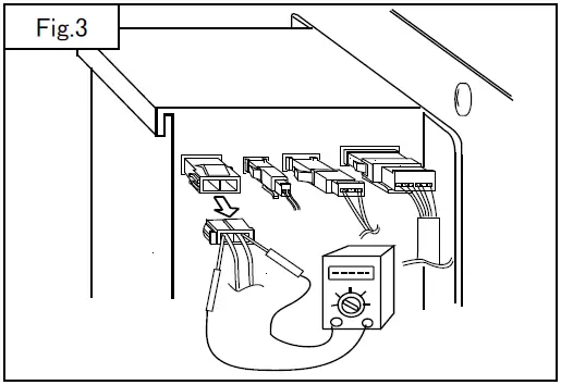
- 【Check 3】 Check the Resistance at the Coil of Compressor (Fig.3)
- Checking point Remove 2 pin couplers at motor cord, and check.
Test result Assessment Approx. 0.84Ω Normal ∞Ω Broken 0Ω Coil of compressor is short circuit 
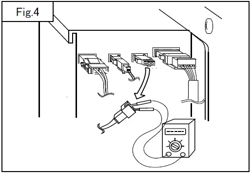
- 【Check 4】 Resistance of Thermistor (Fig.4)
- Checking points Remove the 3 pin couplers from Inverter, and test.
Test result Assessment Approx. 2 kΩ~10 kΩ Normal ∞Ω Broken 0Ω Short Circuit 
- 【Check 5】 Resistance of Control Assy (Fig.5)

- Checking point Remove 6pin coupler. Check the resistance at between terminals brown and black.
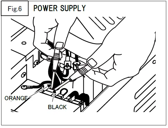
Test result Assessment Dial position OFF ~ 5 Approx. 17kΩ~5kΩ Normal ∞Ω Broken 0Ω Short Circuit - 【Check 6】 Check the temperature controller. (Fig.6)

- Checking points Check the voltage at between terminals ORANGE and BLACK.
Test result Judge Approx. DC12-14V Normal DC 0 V Temperature controller is broken 12V less than Test result Judge Approx. DC12V Normal DC 0 V Temperature controller is broken 11V less than Test result Judge Approx. DC24V Normal DC 0 V Temperature controller is broken 23V less than - 【Check 7】 Checking the operation of the fan motor. (Fig.7)

- Checking point If want to check the start-up of the fan motor directly, can check by connecting the DC24V directly.

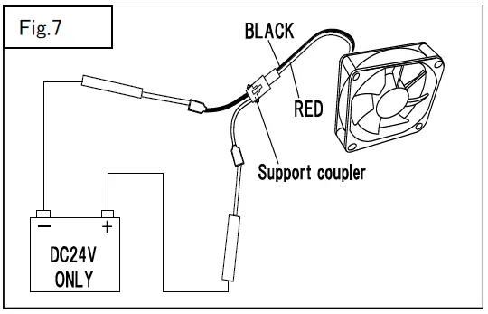
CAUTION
- Please be careful not to mistake the polarity of the power supply.
- When connect with DC24V or wrong polarity, fan motor will fail.
- Please use such as support coupler so as not to short-circuit power.
PROCEDURES FOR REPLACING
How to Replace Cooling Unit
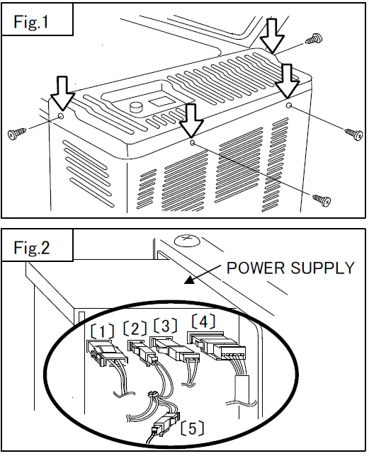
- Remove the motor cover (Fig.1)
- Take out the basket first
- Remove 4 screws which hold Motor Cover.
- Take out the basket first
- Pull out all the couplers at power supply. (Fig.2)
- Motor input coupler. 〔1〕
- Fan motor coupler. 〔2〕
- Thermistor coupler. 〔3〕
- Control assy coupler. 〔4〕
- Fan motor coupler (From refrigerator inside). 〔5〕

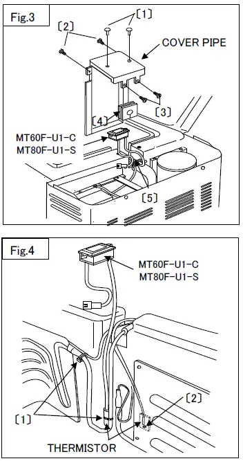
- Remove the cover pipe (Fig.3)
- Remove 2 fasteners. 〔1〕 (MT80F ONLY)
- Remove 2 screws. 〔2〕 (MT60F ONLY)
- Remove 2 screws and take off the pipe cover. 〔3〕
- Detach the rubber grommet. 〔4〕
- Cut the fasteners. 〔5〕
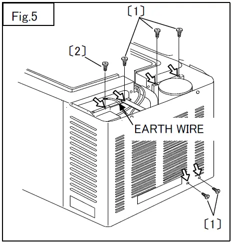
- Remove the thermistor (Fig.4)
- Cut the 2 fasteners. 〔1〕
- Remove screw. 〔2〕
- Remove the thermistor

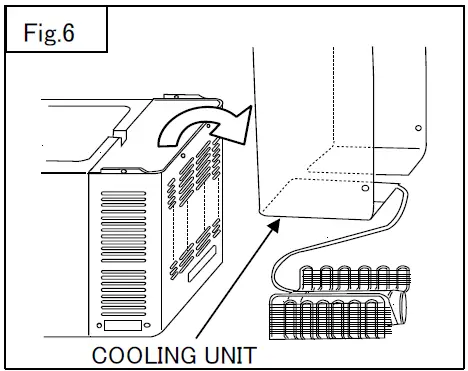
- Remove screws at the hanger of the compressor. (Fig. 5)

- Remove 5 screws. 〔1〕
- Remove the earth wire.
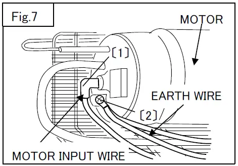
- Remove the cooling unit. (Fig.6), (Fig.7)


- Take out the cooling unit from the cabinet.
WORK TIPS
Please remove the evaporator and capillary tube carefully for not to damage them. In addition, please be careful for not to bend capillary tube.
How to Replace Power Supply
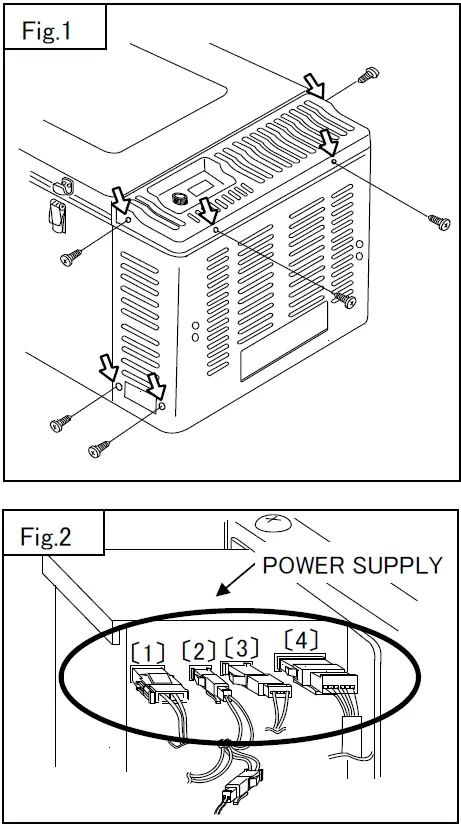
- Remove motor cover. (Fig.1)
- (1) Remove 6 screws.
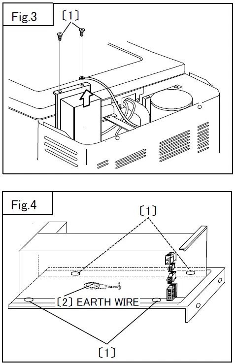
- Pull out all the couplers at the power supply. (Fig.2)
- Motor input coupler. 〔1〕
- Fan motor coupler. 〔2〕
- Thermistor coupler. 〔3〕
- Control assy coupler. 〔4〕

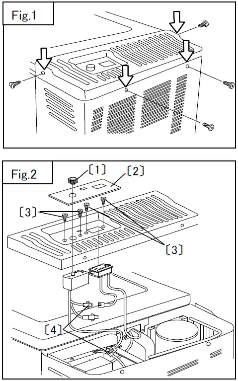
- Remove the power supply (Fig.3)
- Remove 2 screws. 〔1〕
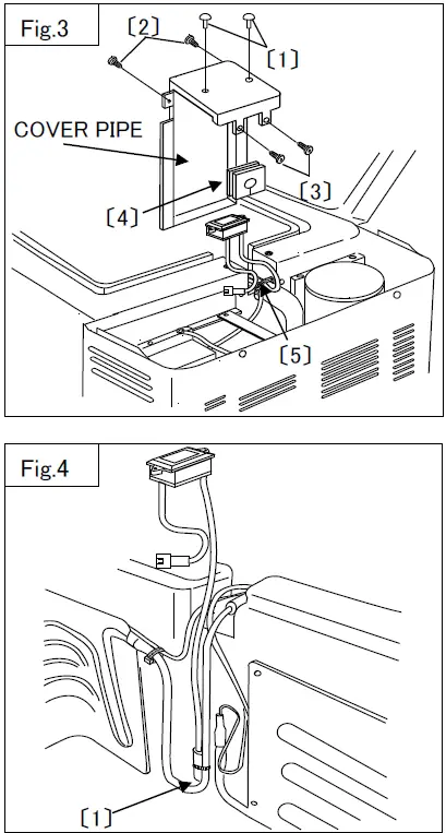
- Remove power supply from cover. (Fig.4)
- Remove 4 screws frome power supply plate.〔1〕
- Remove earth wire. 〔2〕

How to Replace Control Assy and Degital Thermometer (MT60F-U1-C / MT80F-U1-S)
- Remove the motor cover (Fig.1)
- Remove 4 screws which hold Motor Cover.
- Remove the control assy and degital thermometer. (Fig.2)
- Remove the dial assy. 〔1〕
- Take off a mark. 〔2〕
- Remove 4 screws. 〔3〕
- Remove the coupler connection. 〔4〕

- Take out the cover pipe (Fig.3)
- Remove 2 fasteners. 〔1〕(MD80F ONLY)
- remove 2 screws. 〔2〕 (MD60F ONLY)
- Remove 2 screws and take off the pipe cover. 〔3〕
- Detach the rubber grommet. 〔4〕
- Cut the fasteners. 〔5〕
- Take out the thermistor (Fig.4)
- Cut the fasteners. 〔1〕

- Cut the fasteners. 〔1〕
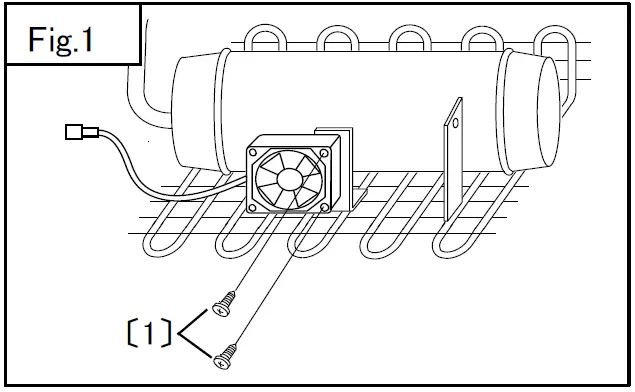
How to Replace Fan Motor
<Compressor side>
- Remove the cooling unit. (See page 13)
- Remove the fan motor. (Fig.1)
- Remove 2 screws. 〔1〕

- Remove 2 screws. 〔1〕
<Refrigerator inside> (MT60F-U1-C)
- Remove the cooling unit. (See page 13)
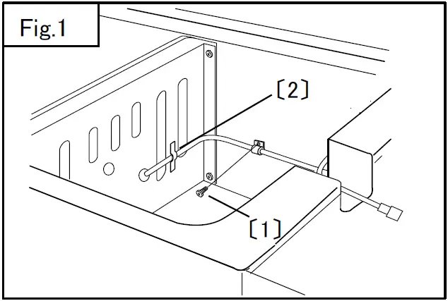
- Remove the fan code. (Fig.1)
- Remove the screw from the clamp. 〔1〕
- emove the sponge seal. 〔2〕

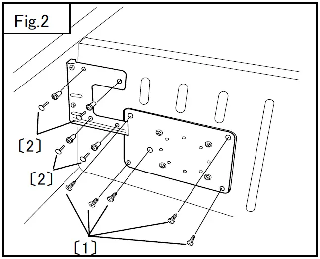
- Remove the fan cover. (Fig.2)
- Remove 5 screws. 〔1〕
- Remove 4 fasteners. 〔2〕

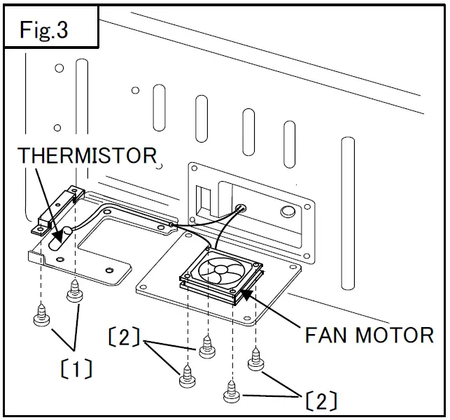
- Take out fan motor (Fig.3)
- Remove 2 screws. 〔1〕
- Remove 4 screws. 〔2〕