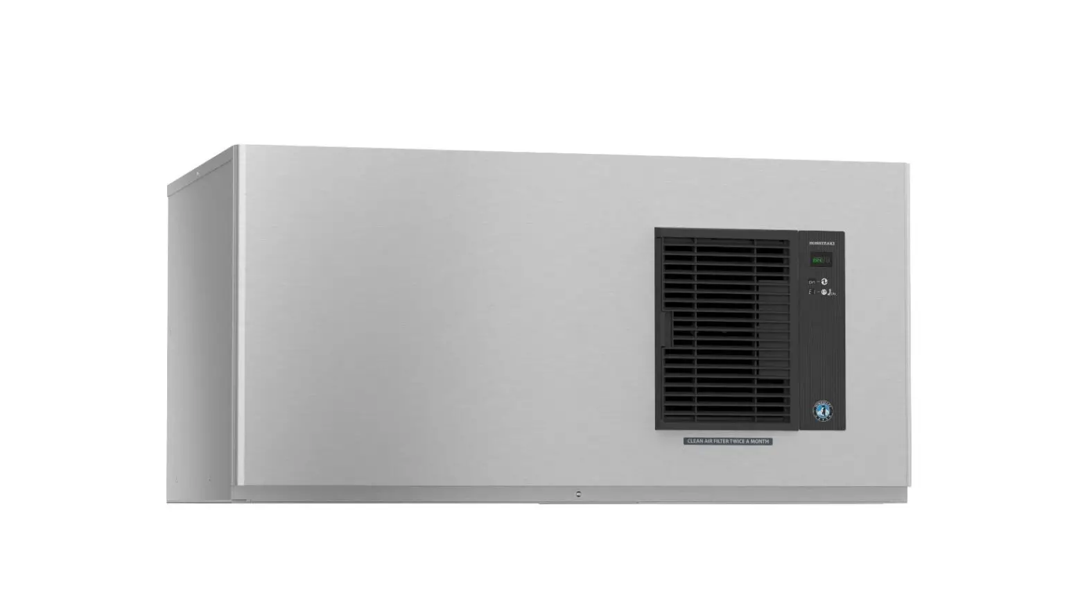
HOSHIZAKI IM-500SAB Modular Cuber Instruction Manual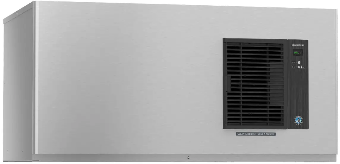
Auxiliary Codes
IM-500SAB
J-0 March 2019
K-0 January 2020
K-1 September 2020
K-2 November 2020
L-0 January 2021
M-0 January 2022
Auxiliary Code Breakdown
The auxiliary code is the first two characters in the serial number. The first character indicates the year. Years progress or regress in alphabetical order. The series runs from “A” through “V” and the letters “I” and “O” are skipped. The second character indicates significant part changes within a year. Base is “0” and this number advances for each change. In cases where there is a letter in parentheses, this designates the month. This is the last character in the serial number. The series runs from “(A)” through “(M)” and the letter “(I)”is skipped. This designation is only included when identifying a parts change within an auxiliary code.
Note About Ordering Parts
Most assemblies cannot be ordered as complete units; parts in the assemblies generally must be ordered separately.
Main Assembly & Refrigeration Circuit
Main Assembly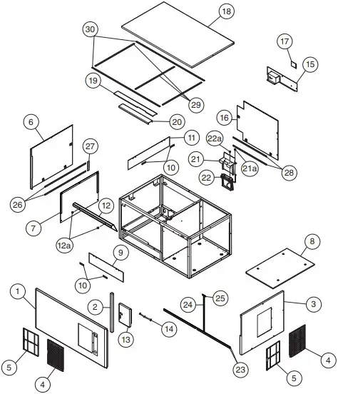
Refrigeration Circuit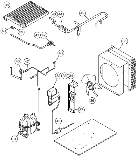
| Title: A. Main Assembly & Refrigeration Circuit Model: IM-500SAB | ||||||||||||
| Index No. | Description | Material or Model Number | Part Number | Required Number | ||||||||
| J-0to K-1 | K-2toL-0(H) | L-0(J)to M-0 | ||||||||||
| Main Assembly | ||||||||||||
| 1 | Front Panel Assembly (includes item 2 and all labels and 1 of item 4 and 5) | 2A8984A01 | 1 | 1 | – | |||||||
| 2B0094A01 | 1 | |||||||||||
| 2 | Front Insulation Separator | 4Y6575P02 | 1 | 1 | 1 | |||||||
| 3 | Right Side Panel(includes 1 of item 4 and 5) | 3B0091A01 | 1 | 1 | 1 | |||||||
| 4 | Louver | 1A0548-01 | 2 | 2 | 2 | |||||||
| 5 | Air Filter | 2A2063G01 | 2 | 2 | 2 | |||||||
| 6 | Left Side Panel | 3B0095G01 | 1 | 1 | 1 | |||||||
| 7 | Separator | 483781G01 | 1 | 1 | 1 | |||||||
| 8 | Chassis Insulation (refrigeration circuit base) | 476401P01 | 1 | 1 | 1 | |||||||
| 9 | Shield A | 377294P01 | 1 | 1 | 1 | |||||||
| 10 | Shield Plate | 477674M01 | 4 | 4 | 4 | |||||||
| 11 | Shield B | 377296P01 | 1 | 1 | 1 | |||||||
| 12 | Cube Guide | 3B0321-01 | 1 | 1 | 1 | |||||||
| 12a | Thumbscrew | 415949G10 | 2 | 2 | 2 | |||||||
| 13 | Control Box Cover | 376269M01 | 1 | 1 | 1 | |||||||
| 14 | Wire Harness | 264542S– | 1 | 1 | 1 | |||||||
| 15 | Upper Rear Panel | 3B0050G01 | 1 | 1 | 1 | |||||||
| 16 | Lower Rear Panel | 3B0094G01 | 1 | 1 | 1 | |||||||
| 17 | Junction Box Cover | 433410-01 | 1 | 1 | 1 | |||||||
| 18 | Top Panel | 1A5445-01 | 1 | 1 | 1 | |||||||
| 19 | Connector Guide A | 312762-01 | 1 | 1 | 1 | |||||||
| 20 | Connector Guide B | 4H5619-01 | 1 | 1 | 1 | |||||||
| 21 | Bin Control Mounting Bracket | 4A6431G01 | 1 | 1 | 1 | |||||||
| 21a | Thumbscrew | 415949G10 | 2 | 2 | 2 | |||||||
| 22 | Bin Control | 2A8598G01 | 1 | 1 | 1 | |||||||
| 22a | Thumbscrew | 415949G10 | 2 | 2 | 2 | |||||||
| 23 | Gasket (Frame) | 1055 mm | 4A0808L02 | 2 | 2 | 2 | ||||||
| 24 | Gasket (Frame) | 490 mm | 4A0808L02 | 1 | 1 | 1 | ||||||
| 25 | Gasket (Frame) | 50 mm | 4A0808L02 | 1 | 1 | 1 | ||||||
| 26 | Gasket (Frame) | 650 mm | 4A0808L02 | 2 | 2 | 2 | ||||||
| 27 | Gasket (Frame) | 120 mm | 4A0808L02 | 1 | 1 | 1 | ||||||
| 28 | Gasket (Frame) | 530 mm | 4A0808L02 | 2 | 2 | 2 | ||||||
| 29 | Gasket (Frame) | 620 mm | 4A0808L02 | 3 | 3 | 3 | ||||||
| 30 | Gasket (Frame) | 1080 mm | 4A0808L02 | 2 | 2 | 2 | ||||||
| 31 | Compressor | P04980-01 | 1 | 1 | 1 | |||||||
| 32 | Start Relay | P02866-01 | 1 | 1 | 1 | |||||||
| 33 | Run Capacitor | 35MFD,400VAC | P02699-01 | 1 | 1 | 1 | ||||||
| 34 | Start Capacitor | 243-292MFD,250VAC | P02867-01 | 1 | 1 | 1 | ||||||
| 35 | Condenser | P03406-01 | 1 | 1 | 1 | |||||||
| 36 | Condenser Fan Motor (includes fan blade) | P02596-01 | 1 | 1 | 1 | |||||||
| 37 | Condenser Fan Bracket | 3B0062A01 | 1 | 1 | 1 | |||||||
| 38 | Evaporator | 2H7526G01 | 1 | 1 | 1 | |||||||
| 39 | Thermistor | P00350-01 | 1 | 1 | 1 | |||||||
| 40 | Thermistor Holder | 315479-01 | 1 | 1 | 1 | |||||||
| 41 | Thermostatic Expansion Valve | 453008-01 | 1 | – | ||||||||
| 4A6938-01 | 1 | 1 | ||||||||||
| 42 | Thermostatic Expansion Valve Cover | 3Y3196P01 | 1 | 1 | 1 | |||||||
| 43 | Thermostatic Expansion Valve Bulb Holder | 3A0112-01 | 1 | 1 | 1 | |||||||
| 44 | Clamp | 443461-01 | 1 | 1 | 1 | |||||||
| 45 | Drier | 4A1113-01 | 1 | 1 | 1 | |||||||
| 46 | Hot Gas Valve | 464103-01 | 1 | 1 | 1 | |||||||
| 47 | Strainer | 441569-02 | 1 | 1 | 1 | |||||||
| 48 | High-Pressure Switch | 463180-04 | 1 | 1 | 1 | |||||||
| 49 | Heat Exchanger | 386557G01 | 1 | 1 | 1 | |||||||
Water Circuit & Mechanism Assembly
Mechanism Assembly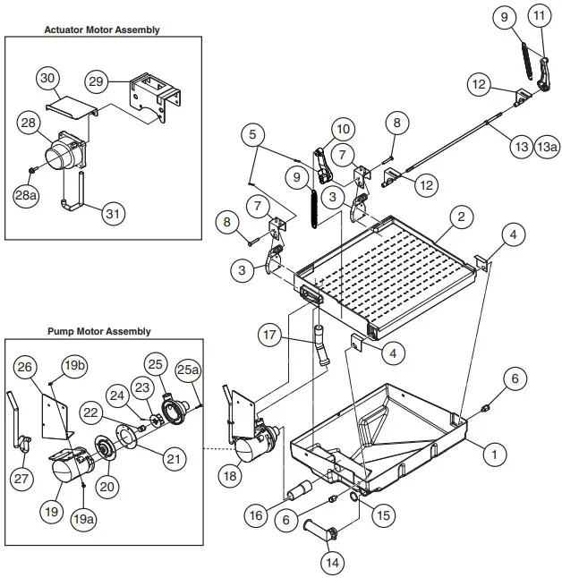
Water Circuit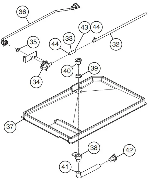
| Title: B. Water Circuit & Mechanism Assembly Model: IM-500SAB | |||||||||||||
| Required Number | |||||||||||||
| J-0 | K-0(J) | M-0 | |||||||||||
| Index | Material or | to | to | to | |||||||||
| No. | Description | Part Number | K-0(H) | L-0 | M-0(C) | M-0(D) | |||||||
| Model Number | |||||||||||||
| 1 | Water Pan | 1H0888-02 | 1 | 1 | 1 | 1 | |||||||
| 2 | Water Plate | 208020G01 | 1 | 1 | 1 | 1 | |||||||
| 3 | Water Pan Hanger | 3H2059-01 | 2 | 2 | 2 | 2 | |||||||
| 4 | Water Pan Bracket | 402957-01 | 2 | 2 | 2 | 2 | |||||||
| 5 | Snap In | 715S-0006 | 2 | 2 | 2 | 2 | |||||||
| 6 | Boss Holder | 4H2582G01 | 2 | 2 | 2 | 2 | |||||||
| 7 | Bearing Plate | 3H1440G03 | 2 | 2 | 2 | 2 | |||||||
| 8 | Shaft B | 4H1184-02 | 2 | 2 | 2 | 2 | |||||||
| 9 | Spring | 481332M01 | 2 | 2 | 2 | 2 | |||||||
| 10 | Cam A | 306543G04 | 1 | 1 | 1 | 1 | |||||||
| 11 | Cam B | 376546P01 | 1 | 1 | 1 | 1 | |||||||
| 12 | Cam Shaft Bearing | 3X8307-02 | 2 | 2 | 2 | 2 | |||||||
| 13 | Cam Shaft | 425511G02 | 1 | 1 | 1 | 1 | |||||||
| 13a | Cotter Pin | 711S-0212 | 1 | 1 | 1 | 1 | |||||||
| 14 | Drain Pipe | 315530-01 | 1 | 1 | 1 | 1 | |||||||
| 15 | O-Ring | 7611-G025 | 1 | 1 | 1 | 1 | |||||||
| 16 | Suction Tube | 4Y6641R01 | 1 | 1 | 1 | 1 | |||||||
| 17 | Discharge Tube | 4Y6642R01 | 1 | 1 | 1 | 1 | |||||||
| 18 | Pump Motor Assembly (includes items 19 through 27) | 261541A01 | 1 | 1 | 1 | 1 | |||||||
| 19 | Pump Motor | 2A2758-01 | 1 | 1 | 1 | 1 | |||||||
| 19a | Hex Head Bolt | 7B0230412 | 4 | 4 | 4 | 4 | |||||||
| 19b | Flange Nut | 7J02-0400 | 4 | 4 | 4 | 4 | |||||||
| 20 | Pump Flange | 3A2988-01 | 1 | 1 | 1 | 1 | |||||||
| 21 | Pump Gasket | 4A2974-01 | 1 | 1 | 1 | 1 | |||||||
| 22 | Mechanical Seal | 465627-01 | 1 | 1 | 1 | – | |||||||
| 465627-03 | 1 | ||||||||||||
| 23 | Impeller | 433522-01 | 1 | 1 | 1 | 1 | |||||||
| 24 | Pin | 4A0648-01 | 1 | 1 | 1 | 1 | |||||||
| 25 | Pump Housing | 261284P01 | 1 | 1 | 1 | 1 | |||||||
| 25a | Screw | 4×20 | 4A3871-01 | 4 | 4 | 4 | 4 | ||||||
| 26 | Pump Motor Bracket | 3B0111-01 | 1 | 1 | 1 | 1 | |||||||
| 27 | Pump Motor Tube | 1050 mm | 8104-0004 | 1 | 1 | 1 | 1 | ||||||
| 28 | Actuator Motor | P02382-01 | 1 | 1 | 1 | 1 | |||||||
| 28a | Hex Head Bolt | 6×20 | FBK0620S0 | 2 | 2 | 2 | 2 | ||||||
| 29 | Actuator Motor Bracket | 3Y2924M01 | 1 | 1 | 1 | 1 | |||||||
| 30 | Actuator Motor Shield | 476684M01 | 1 | 1 | 1 | 1 | |||||||
| 31 | Actuator Motor Tube | 8104-0003 | 1 | 1 | 1 | 1 | |||||||
| 32 | Water Supply Pipe | 376015G01 | 1 | 1 | 1 | 1 | |||||||
| 33 | Silicon Hose | 50 mm | 7730I3812 | 1 | 1 | 1 | 1 | ||||||
| 34 | Inlet Water Valve | SP-5616 | P01559-01 | 1 | – | ||||||||
| 4A6722-03 | 1 | 1 | 1 | ||||||||||
| 35 | Rubber Gasket | 413854-03 | 1 | 1 | 1 | 1 | |||||||
| 36 | Water Supply Pipe A | 376037A01 | 1 | 1 | 1 | 1 | |||||||
| 37 | Drain Pan | 208186-01 | 1 | 1 | 1 | 1 | |||||||
| 38 | Drain Pipe | 376019P01 | 1 | 1 | 1 | 1 | |||||||
| 39 | Packing | 413857-02 | 1 | 1 | 1 | 1 | |||||||
| 40 | Drain Flange | 418296-01 | 1 | 1 | 1 | 1 | |||||||
| 41 | Hose B | 436599-01 | 1 | 1 | 1 | 1 | |||||||
| 42 | Drain Fitting | 477775G01 | 1 | 1 | – | ||||||||
| 4A5527-02 | 1 | 1 | |||||||||||
| 43 | Hose Clamp | 13.5 mm | 427443-07 | 1 | – | ||||||||
| 44 | 15 mm | 435934-03 | 1 | 2 | 2 | 2 | |||||||
Control Box Assembly
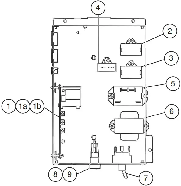
| Title: B. Control Box Assembly Model: IM-500SAB | ||||||||||||
| Index No. | Description | Material or Model Number | Part Number | Required Number | ||||||||
| J-0to M-0 | ||||||||||||
| 1 | Control Board | P01873-01 | 1 | |||||||||
| 1a | Control Board Support | P04204-01 | 4 | |||||||||
| 1b | Control Board Fuse | 1A-6.3A,250VAC | P01873F01 | 1 | ||||||||
| 2 | Fan Motor Capacitor | 6MFD,220VAC | 443158-02 | 1 | ||||||||
| 3 | Pump Motor Capacitor | 5.5MFD,250VAC | 443192-03 | 1 | ||||||||
| 4 | Actuator Motor Capacitor | 0.8MFD,250VAC | 416969-01 | 1 | ||||||||
| 5 | Compressor Relay | 120VAC | 4A3140-01 | 1 | ||||||||
| 6 | Control Transformer | 3A4395-01 | 1 | |||||||||
| 7 | Toggle Switch | P00033-01 | 1 | |||||||||
| 8 | Fuse Holder | P02829-01 | 1 | |||||||||
| 9 | Fuse | AGC-5A, 250VAC | P04203-01 | 1 | ||||||||
Accessories & Labels
| Title: D. Accessories & Labels Model: IM-500SAB | |||||||||||
| Index No. | Description | Material or Model Number | Part Number | Required Number | |||||||
| J-0to M-0 | |||||||||||
| 1 | Operation Label | 376391L01 | 1 | ||||||||
| 2 | Mounting Bracket | 4A6437-01 | 2 | ||||||||
| 3 | Hex Head Bolt | 5×12 | 7B0230512 | 2 | |||||||
QR Code