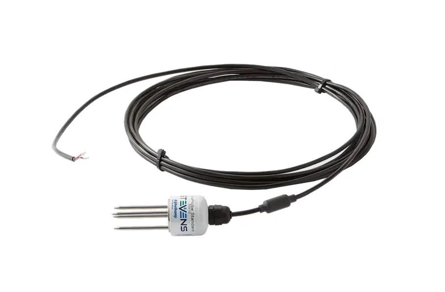
HydraProbe SDI-12 Soil Moisture Sensor User Guide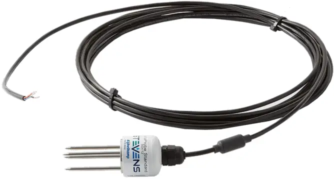
Introduction
SDI-12 is a specialized communication protocol designed specifically for environmental sensors.
It’s an ideal choice for remote and low-power applications due to its minimal power consumption and reliable communication with minimal noise and interference.
Being a standardized protocol, SDI-12 allows for seamless integration of sensors and data loggers from different manufacturers into the same system, which simplifies setup and saves time and resources.
However, if you require longer communication distances, higher data rates, or need to interact with a wider range of devices, Modbus may be a better choice.
You can learn more about SDI-12 by visiting http://www.sdi-12.org
Older versions of Hydra Probe firmware may have different commands, contact Stevens Water for more information
Technical Specifications
| Power | Requirements | 9 to 16 VDC (12VDC Ideal) |
| Consumption | 1 mA Idle, 25 mA for 2s Active | |
| Wiring | Red | + Power Input |
| Black | Ground | |
| Blue | SDI-12 Data Signal |
How To Use
Using SDI-12 involves setting up a master-slave communication system between devices.
The master device sends requests to the slave devices to read or write data, and the slave devices respond with the requested data.
The basic steps to use SDI-12 are below:
- Set up the physical connection: Connect the SDI-12 device to your data logger or microcontroller using a compatible interface cable.
The cable should have three wires: power (positive and negative) and data. - Set up the SDI-12 communication parameters: Configure your data logger or microcontroller to communicate with the SDI-12 device.
- Assign SDI-12 addresses: Assign a unique SDI-12 address to each slave device on the network.
- Send SDI-12 commands: The commands typically include a command code (e.g., “M” for measurement) and an address (e.g., “0” for the first device on the bus).
The device will respond with the requested data.
Many data loggers have a “transparent mode” to communicate directly with the sensor. - Interpret the data received from the SDI-12 device: The data may be in a specific format or units depending on the device type.
- Test: Test the communication between the devices and make any necessary adjustments to the commands or settings.
Addressing
The first character of any command or response on SDI-12 is the sensor address.
A lowercase ‘a’ is used to represent the address.
Each SDI-12 sensor must have its own unique address.
The default address is “0”.
| SDI-12 Command | Response | Description |
| aAb! | b | Change Sensor Address a – Sensor Address b – New Sensor Address |
Identification
A request for identification will return the sensor address, part number, firmware version, sensor version, calibration, and serial number.
| SDI-12 Command | Response | Description |
| aI! | a12STEVENSWnnnnnv.vvvcSNxxxxxxxx | Send Identification a – Sensor address 12 – SDI-12 protocol version STEVENSW – Manufacturer nnnnn – Part number v.vvv – Firmware version c – Calibration xxxxxxxx – Serial number |
Measurements
| SDI-12 Command | Response | Description |
| aM! | atttn | Request Measurement a – Sensor address ttt – seconds (000 – 999) until the measurement is ready n – number of data fields (1-9) in the measurement |
| aD0! | a<F><I><G> | Send Measurement Readings F – Soil Moisture I – Bulk EC (Temp Corrected) G – Temperature (C) |
| aD1! | a<H><J><L> | Send Measurement Readings H – Temperature (F) J – Bulk EC L – Real Dielectric Permittivity |
| aD2! | a<M><K><O> | Send Measurement Readings M – Imaginary Dielectric Permittivity K – Pore Water EC O – Dielectric Loss Tangent |
| aM1! | atttn | Request Measurement ttt – seconds (000 – 999) until the measurement is ready n – number of data fields (1-9) in the measurement |
| aD0! | a<L><M><N> | Send Measurement Readings L – Real Dielectric Permittivity M – Imaginary Dielectric Permittivity N – Imaginary Dielectric Permittivity (Temperature Corrected) |
| aD1! | a<O><P> | Send Measurement Readings O – Dielectric Loss Tangent P – Diode Temperature |
The following tables list the values and units:
| Selector Order | Parameter | Unit |
| F | Soil Moisture | Water fraction by Volume (wfv) |
| G | Soil Temperature | Celsius (C) |
| H | Soil Temperature | Fahrenheit (F) |
| I | Bulk EC (Temperature Corrected) | Siemens/Meter (S/m) |
| J | Bulk EC | Siemens/Meter (S/m) |
| K | Pore Water EC | Siemens/Meter (S/m) |
| L | Real Dielectric Permittivity | – |
| M | Imaginary Dielectric Permittivity | – |
| N | Imaginary Dielectric Permittivity (Temperature corrected) | – |
| O | Dielectric Loss Tangent | – |
| P | Diode Temperature | Celsius (C) |
| SDI-12 Measurement Sets | |||||||||
| Command | P1 | P2 | P3 | P4 | P5 | P6 | P7 | P8 | P9 |
| aM! and aC! | F | I | G | H | J | L | M | K | O |
| aM1! and aC1! | L | M | N | O | P | ||||
Pore Water Offset
| SDI-12 Command | Response | Description |
| aXR_PWOS! | a<Current Offset> | Read Pore Water Offset |
| aXW_PWOS_<New Offset>! | a<New Offset> | Write Pore Water Offset |
| aXD PWOS! | a+3.4 | Reset Pore Water Offset to default 3.4 |
Calibration
The following extended command will change the coefficients in one of two general formulas that translate the real dielectric permittivity to soil moisture.
In many cases, the Hydra Probe will not need to be recalibrated.
The default General calibration has been heavily reviewed and will provide reasonable accuracy for most applications.
If you need to change the calibration or if a custom calibration is required, we recommend referring to the Hydra Probe user manual for more information.
| SDI-12 Command | Response | Description |
| aXR_SOIL! | a<G/O/R/C/K> | Get Current soil type G – General O – Organic R – Rockwool C – Custom 1 K – Custom 2 |
| aXW_SOIL_<New Soil Type>! | a<G/O/R/C/K> | Write New Soil Type G – General O –Organic R – Rock Wool C – Custom 1 K – Custom 2 |
| aXR_COEFA! | a<A> | Read coefficient A |
| aXR_COEFB! | a<B> | Read coefficient B |
| aXR_COEFC! | a<C> | Read coefficient C |
| aXR_COEFD! | a<D> | Read coefficient D |
| aXR_COEFE! | a<E> | Read coefficient E |
| aXR_COEFF! | a<F> | Read coefficient F |
| aXR_COEF! | a<A><B><C><D><E><F> | Read all coefficients |
| aXW_COEFA_<A>! | a<A> | Write coefficient A |
| aXW_COEFB_<B>! | a<B> | Write coefficient B |
| aXW_COEFC_<C>! | a<C> | Write coefficient C |
| aXW_COEFD_<D>! | a<D> | Write coefficient D |
| aXW_COEFE_<E>! | a<E> | Write coefficient E |
| aXW_COEFF_<F>! | a<F> | Write coefficient F |
| aXD_COEF! | a<A><B><C><D><E><F> | Reset all coefficient to default |
Accuracy and Ranges
| Parameter | |
| Soil moisture for inorganic mineral soils | Accuracy*: +/- 0.01 WFV for most soils ( m3,m-3) +/- <0.03 for fine textured soil (typical) Range: From Complete Dry to Full Saturation (0% to 100% of saturation) |
| Bulk EC | Accuracy: +/- 2.0% or 0.02 S/m Whichever is greater Range: 0 to 1.5 S/m |
| Temperature | Accuracy: +/- 0.3 °C Range: -40 to 75 °C |
| Inter-Sensor Variability | +/- 0.012 WFV (Typical) |
| Pore Water EC | Hillforts Equation, depends on soil conditions |
*Accuracy of soil moisture depends on the soil and is highly variable.
Model Numbers
| Version Part # Suffix | |
| 02 | Professional, w/25 ft. cable |
| 04 | Professional, w/50 ft. cable |
| 06 | Professional, w/100 ft. cable |