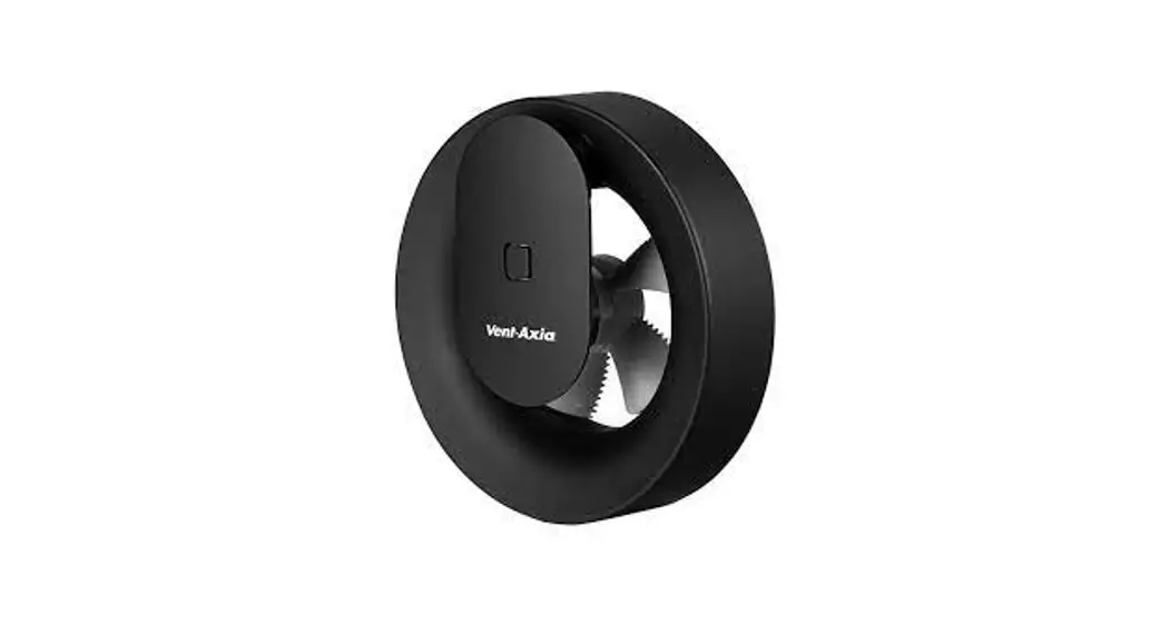
zwart 100mm Bathroom fan humidity sensor timer Silent
User Manual
Bathroom fan humidity sensor timer Silent
Explanation
Diagrams
Dimensions
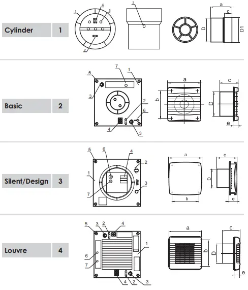
| 1 – Cylinder | A | D1 | D | C |
| Ø100 mm | 91 mm | 104 mm | 100 mm | 31 mm |
| Ø125 mm | 93 mm | 129 mm | 125 mm | 31 mm |
| Ø150 mm | 108 mm | 154 mm | 150 mm | 46 mm |
| 2 – Basic | A | B | C | D | E |
| Ø100 mm | 160 mm | 135 mm | 90 mm | 100 mm | 25 mm |
| Ø125 mm | 180 mm | 150 mm | 94 mm | 125 mm | 25 mm |
| Ø150 mm | 207 mm | 182 mm | 106 mm | 150 mm | 25 mm |
| 3 – Silent | A | B | C | D | E |
| Ø100 mm | 150 mm | 120 mm | 126 mm | 100 mm | 32 mm |
| Ø125 mm | 176 mm | 140 mm | 132 mm | 125 mm | 34 mm |
| Ø150 mm | 206 mm | 165 mm | 154 mm | 150 mm | 36 mm |
| 4 – Louvre | A | B | C | D | E |
| Ø100 mm | 166 mm | 150 mm | 90 mm | 100 mm | 30 mm |
| Ø125 mm | 186 mm | 170 mm | 94 mm | 125 mm | 30 mm |
Designation
Our fans are designed for ventilation of domestic and similar premises (apartments, offices, stores, garages, kitchens, bathrooms, toilets, and other rooms, heated in wintertime).
Fans (but exhaust fan for Cylinder Serie) areas and are designed for wall or ceiling mounting.
Cylinder-series fans may be used for both input and output ventilation and are to be installed in ventilation ducts. Our fans are designed for continuous work without switching off mains.
The design of the fans is constantly improved and updated, and some models may differ from what is described in this manual.
Basic Specifications
Fans identification, diagrammatic representation of appearance, installation dimensions, and peculiarities of design are given in Table 1.
The fans are designed for operation from an AC power supply with a voltage of 220-240 V and a frequency of 50 Hz. The 12V fans are suitable for 12V – 50Hz. These fans are not equipped with a built-in transformer.
| Nominal output in terms of extract air capacity is: | The nominal electric power of the fans is: |
| – for 100 mm: 82 -107 cubic meters/hour ( ±5%) – for 125 mm: 157 – 232 cubic meters/ hour ( ±5%) – for 150 mm: 260 – 348 cubic meters/ hour ( ±5%) | – For 100 mm: -9/22 W; – For 125 mm: -16/26 W. – For 150 mm: -24/32 W. |
The capacity of fans depends strongly on the shape of the air duct. Bends, type of ducting, length, and kinks can influence the airflow. In the most ideal situation, the fan will have a good operation with a duct length of a maximum of 5 meters.
Equalized sound level at a 3-meter distance does not exceed 40 dBA. Fans are designed for operation at air temperatures within 0°C to 45°C.
Safety Requirements
The fans comply with the requirements according to the EU norms and directives, to the relevant EU-Low Voltage Equipment Directives, EU-Directives on Electromagnetic Compatibility Level of protection from access to hazardous parts, and waterproof:
IPX4- Cylinder
IP24- Louvre
IP34- Design, Silent, Basic
The replacement of electric wire must be performed by a skilled electrician. Fan operation beyond the operational temperature range as well as in rooms with ambient air containing aggressive admixes is prohibited.
For well-functioning and safety matters, it is necessary to comply with your national electricity standards. The dutch electrical wiring colors for devices are:
L = colour brown (phase) LT= colour black (switch wire)
N = colour blue (zero, 0)
Note: internal wiring colors of the fan may not necessarily match the wiring colors of your local electrical installation.![]() ATTENTION! Fan operation when restrictions, being able to damage or jam blades of operation wheel, in flowing part of the case, is prohibited. Precautions must be taken to avoid the back-flow of gases into the room from the open lue of gas or other open-fire appliances.
ATTENTION! Fan operation when restrictions, being able to damage or jam blades of operation wheel, in flowing part of the case, is prohibited. Precautions must be taken to avoid the back-flow of gases into the room from the open lue of gas or other open-fire appliances.
Preparation for device operation
Attention! All maintenance works and connections of fans are to be performed only after switching off mains.
The direction of air-charging is to comply with the direction of the arrow on the fan case. Cylinder fans are mounted in ventilation air ducts from both ends and nipped with clamps
Fans of other models are mounted in the hole of the air duct and mounted on the wall or ceiling with dowels.
If necessary, ensure conditions to prevent free access to the impeller and current-carrying parts of the fan by protective means from the side of the outcome (ventilation grille, protective cowl, and so on).
The connection of fans to the electric power supply is shown in Fig. 1-4. An order in which connection of fans should be made is indicated in the Table shown below.
| Type | Operations of connection to a power supply |
| Cylinder | Remove protective grid (except for model Cylinder). Take away a protective cowl. Pass power supply cords through hole 3, strip the wire rags at length 7-8 mm to clamp terminals 4 against the stop to the metal part of the clamp, and tighten them with rews. Fix cords with the help of clip 2. Reinstall protective cowl and grid back. |
| Basic, Design, Silent & Louvre | Remove protective grid and cover. Pass power supply cords through hole 3 (having cut a thin plastic pierce on the spot of opening eforehand). Strip the wire rags at length 7-8 mm to clamp terminals against the stop to the metal part of the clamp and tighten them with crews. Fix cords with the help of clip 2. Reinstall the cover and protective grid back. |
| fig. 1 1 – housing; 2 – clip of power supply cords; 3 – holes for power supply cords; 4 – clamp terminal. | Fig. 3 1 – housing; 2 – clip of power supply cords; 3 – holes for power supply cords; 4 – clamp terminal; 5 – holes for fan mounting; 6 – potentiometer (Hydro); 7 – potentiometer (Timer). |
| Fig. 2 1 – housing; 2 – clip of power supply cords; 3 – holes for power supply cords; 4 – clamp terminal; 5 – holes for fan mounting; 6 – light. 7 – potentiometer (Timer). | Fig. 4 1 – housing; 2 – clip of power supply cords; 3 – holes for power supply cords; 4 – clamp terminal; 5 – holes for fan mounting; 6 – potentiometer (Timer); 7 – potentiometer (Hydro). |
Diagrams
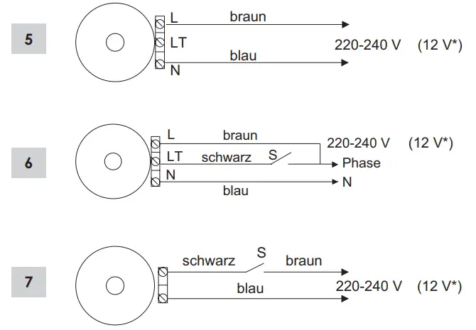
Fig.5. In case your fan is equipped with a humidity sensor in combination with a timer, fig.5. should be followed. These fans will switch on automatically if humid air (60-90%, see fig.10) is sensed. After the level has been reached (50-90%), the fan will continue operation for the time the timer has been set (2-30min.) Time can be regulated by potentiometer T. To increase the delay, turn clockwise, and for decrease turn anti-clockwise. This diagram can also be applied to fans with a motion sensor equipped. Fig.6. For fans equipped with timers that have to be started with an external switch fig.6. can be used. The fan will start operating as soon as it is switched on the mains. When LT has switched off the mains, the fan will continue working for the time the timer has been set (2-30min.). Fig.6. Can also be applied to fans equipped with a timer and humidity sensor which have to be started with an external switch. The fan will start operating as soon as it is switched on the mains or when humid air (60-90%) has been sensed. When LT is switched off the mains, or the humidity level has decreased below 60%, the fan will continue operation for the time the timer has been set. Fig.7. For all fans of the model Basic, Design, Louvre, and Cylinder without any special features. In this situation, an external switch is applied. Note: the wire from the switch is lacking.
![]() Fan with humidity sensor
Fan with humidity sensor
The sensitivity can be regulated by potentiometer H by rotation clockwise to increase, and anti-clockwise to decrease the level.
Maintenance
Fan maintenance should be performed only after switching off mains. Maintenance mainly consists of periodic cleaning of the fan’s surfaces of duct and dirt.
The fan should be cleaned with a soft cloth wet in soapy water. After cleaning, the surfaces should be wiped dry.
Warranty
From the date of purchase, we offer a 5-year warranty on our products. The receipt from your purchase is your certificate of guarantee as well and should be presented whenever a guarantee is claimed.
Failures caused by material and/ or manufacturing faults are covered by a replacement guarantee free of charge, on the following restrictions:
– The fan is placed according to this mounting instruction.
– The fan is maintained correctly.
– The fan is correctly installed.
The warranty is limited to the replacement of the fan, after inspection of our technical service. Costs for conversion, transport or working hours are not to be compensated for. Manufacturers can not be held responsible for any indirect damage.


