![]()
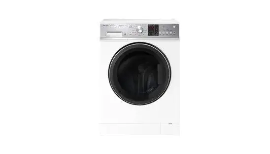
FRONT LOADER WASHING MACHINE
__________
WH1060P3, WH1060J, WH9060P, WH9060J, WH8560F, WH8560P, WH8560J, WH8060F,
WH8060P, WH8060J, WH7560P, WH7560J, WM1490P & WH1060P4
INSTALLATION GUIDE
SAFETY AND WARNINGS
 | Electric Shock Hazard Failure to follow this advice may result in electric shock or death. • If you are using an extension cord or a portable electrical outlet device (eg multi-socket outlet box), ensure that it is positioned so that it does not come into contact with water or moisture. |
READ AND SAVE THIS GUIDE
Installation
- For guidance on how to install your product, please refer to installation instructions contained in this document.
- Install the washer on a solid and level floor surface ensuring it has at least 20 mm clearance on each side. The washer must not be installed on any textured floor coverings (eg carpet, rugs).
- This washer must not be installed or operated on a plinth.
- Ensure the installation provides accessibility to the plug or incorporate a switch in the fixed wiring in accordance with the wiring rules to allow disconnection of the appliance from the supply after installation.
Water supply requirements:
- Inlet water pressure: Max. 1MPa (145psi), Min. 30kPa (4.5psi)
- Inlet water flow rate: Min. 6 litres/minute
- A pressure-reducing valve must be installed if pressure is higher than 1MPa.
- For optimum wash performance check the supply pressure is within the recommended range.
- New hose sets provided with the washer should be used to connect the washer to the water mains. Old hose sets should not be re-used.
- We recommend the inlet hose(s) are changed every 5 years. WARNING: Failure to do so may result in a flood and damage to property.
- The hot water temperature should not exceed 65°C and the cold water temperature not exceed 35°C. Temperatures above these may cause the washer to fault or cause damage to the washer.
SAVE THESE INSTRUCTIONS
The models shown in this installation guide may not be available in all markets and are subject to change at any time. For current details about model and specification availability in your country, please go to our website www.fisherpaykel.com or contact your local Fisher & Paykel dealer.
SUPPLIED PARTS
- Keep all packing materials until the unit has been inspected.
- Inspect the product to ensure there is no shipping damage. If any damage is detected contact the dealer or retailer you bought the product from to report the damage.
- Fisher & Paykel is not responsible for shipping damage.
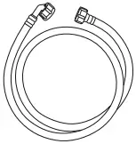
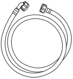
Inlet hose cold (1) Inlet hoses hot (1) Only WM1490P1
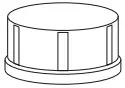
Inlet valve cap (1) Only WM1490P1 Drain hose guide (1)
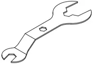
Plastic plug (4) User guide (1) Spanner (1)
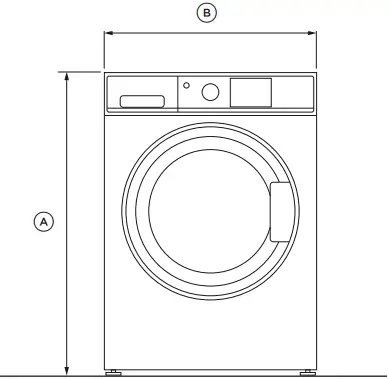
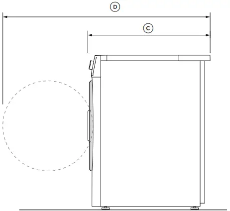
PRODUCT DIMENSIONS
WH8060P, WH8560P, WH9060J, WH9060P, WH1060P3, WM1490P, WH8060F, WH8560F, WH1060P4 models
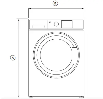
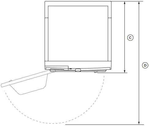
FRONT PROFILE

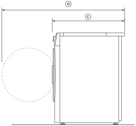
PLAN
| PRODUCT DIMENSIONS | MM |
| A Overall height* • Min • Max | 850 865 |
| B Overall width | 600 |
| C Overall depth** | 655 |
| D Depth with door open | 1075 |
* Exact height is dependent on foot adjustment
** Including dial and door (when closed)
Actual product dimensions may vary by ± 2mm.
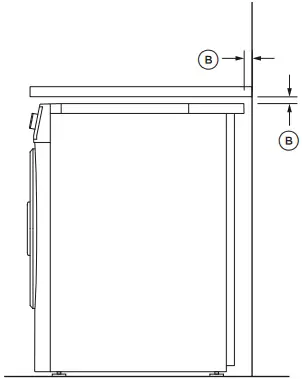
CAVITY & CLEARANCE DIMENSIONS
WH8060P, WH8560P, WH9060J, WH9060P, WH1060P3, WM1490P, WH8060F, WH8560F, WH1060P4 models
* Front panel of the product
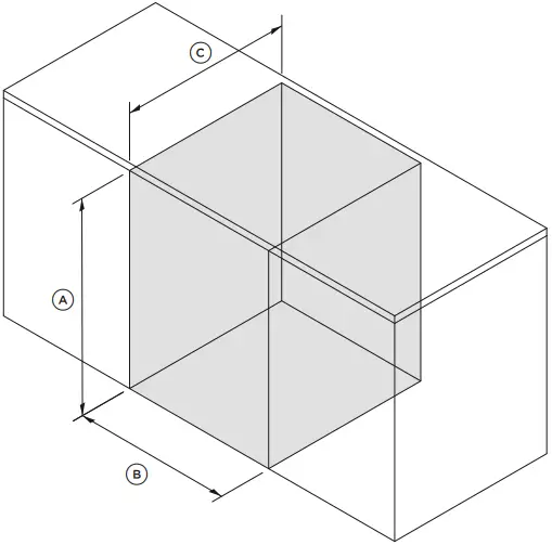
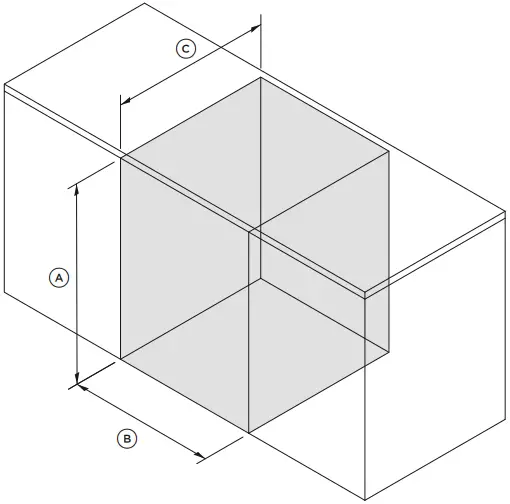
ISOMETRIC
| CAVITY DIMENSIONS | MM |
| A Minimum cavity height | 870 |
| B Minimum cavity width | 640 |
| C Minimum cavity depth. • Flush with front panel of the product*. • In cupboard | 650 695 |
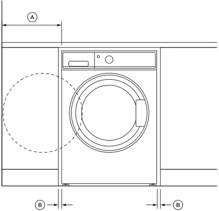
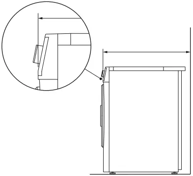
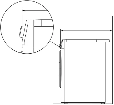
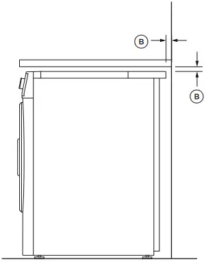
FRONT PROFILE
| CLEARANCE DIMENSIONS | MM |
| A Minimum washer door clearance to adjacent wall | 320 |
| B Minimum gap clearance to adjacent product or cabinetry* | 20 |
* Applies to sides, top and rear
Actual dimensions may vary by ± 2mm.
For paired installation dimensions please visit fisherpaykel.com
PRODUCT DIMENSIONS
WH8060J & WH7560 models
FRONT PROFILE
PLAN
| PRODUCT DIMENSIONS | MM |
| A Overall height* • Min • Max | 850 865 |
| B Overall width | 600 |
| C Overall depth** | 595 |
| D Depth with door open | 1015 |
* Exact height is dependent on foot adjustment
** Including dial and door (when closed)
Actual product dimensions may vary by ± 2mm.
CAVITY & CLEARANCE DIMENSIONS
WH8060J & WH7560 models
* Front panel of the product
ISOMETRIC
| CAVITY DIMENSIONS | MM |
| A Minimum cavity height | 870 |
| B Minimum cavity width | 640 |
| C Minimum cavity depth. • Flush with front panel of the product* • In cupboard | 580 635 |

FRONT PROFILE
| CLEARANCE DIMENSIONS | MM |
| A Minimum washer door clearance to adjacent wall | 320 |
| B Minimum gap clearance to adjacent product or cabinetry* | 20 |
* Applies to sides, top and rear
Actual dimensions may vary by ± 2mm.
For paired installation dimensions please visit fisherpaykel.com
ELECTRICAL & PLUMBING CONNECTION
CONNECTION LOCATIONS / LENGTHS
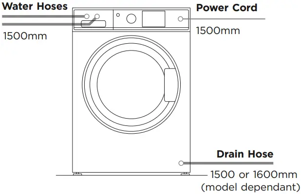
DRAINAGE HEIGHTS
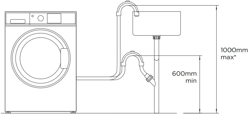
* Recommended standpipe height is 800mm
SPECIFICATIONS
| ELECTRICAL | |
| Supply | 220 – 240 V, 50 Hz |
| Service | 10 amp circuit |
| PLUMBING | |
| Pressure | max 1 MPa (150psi) min 30 kPa (4.5psi) |
| Flow rate at tap | Min. 6 litres/minute |
| Cold water temp | max 35°C |
| Hot water temp | max 65°C |
UNPACKING
Your washer is heavy, we recommend two persons to move and install.
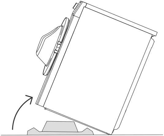
1 Remove the outer packaging including the polystyrene packer and plastic wrapping.
2 Lift the washer off the base.
3 Remove all packaging and accessories from inside the drum.
4 Dispose of all packaging sustainably, ensuring these materials are kept out of the reach of children.
WATER SUPPLY
Water supply requirements
If you have an uncontrolled water heating source (eg a wet back or solar heating system) you should fit a tempering valve. This will ensure the hot water temperature remains within safe limits. Contact your registered plumber to select and install the tempering valve.
Your cold water should not exceed 35°C and your hot water should not exceed 65°C. Temperatures above these may cause the washer to fault or cause damage to the washer.
Inlet hose(s)
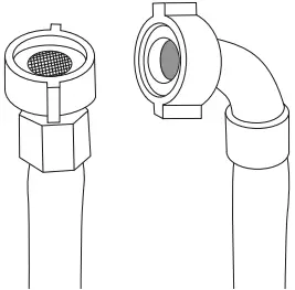
Failure to adhere to the following guidance may result in a flood and damage to property. Only use the new hose set(s) provided with your washer.
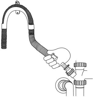
1 Connect the straight ends of the inlet hose(s) to the tap(s), there are washers fitted in both ends.
2 Connect the elbow ends to the corresponding washer inlet valves. If present, the hot valve is coloured orange to make this easier.
3 Tighten the inlet hose(s) ends by hand until the hose seal just makes contact with the tap-sealing face. Continue to tighten a further half-turn.
4 Make sure there are no kinks in the hose(s).
5 Turn the tap(s) on and check for leaks. Check for leaks again after 24 hours.
Cold supply only
If you only have a cold water supply, you must connect the inlet valve cap (blanking cap) provided with your washer to the hot inlet valve. The cap prevents water leaking out of the hot valve. This appliance incorporates backflow protection complying with AS3500.1/IEC61770. No further backflow protection is required for connection to the water supply.
Your washer has an internal heater to heat water. If you do not connect a hot water inlet hose, your washer will automatically recognise there is no hot water supply and its internal heater will heat the cold water to the selected cycle temperature.
DRAINING
In multi-storey apartments or any upper floor, the washer should be installed on a floor equipped with a drain. Draining must comply with local by-laws.
Place the drain hose in a tub or standpipe
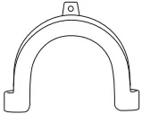
The hose guide is used to hold the drain hose over the tub or standpipe.
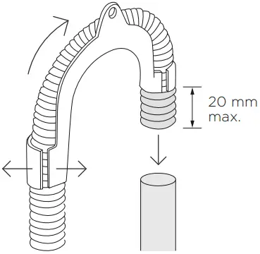
1 Flex the guide apart and pull the hose through the guide.
2 Ensure a maximum of 20mm of the hose is left exposed at the end.
3 Secure the hose guide to prevent it dislodging from the standpipe or tub.
If the drain hose is placed on the ground or if the tub or standpipe is less than 600mm high, the washer will continuously drain (siphon) while being filled.
Tub or standpipe height should be a minimum of 600mm.
Regularly check that your tub or standpipe is free from lint or other obstructions. This may affect operation or cause flooding.
Attach drain hose to spigot
The hose guide is used to hold the drain hose high enough to prevent continuous draining (siphoning).
1 Flex the guide apart and pull the hose through the guide.
2 Secure the hose guide to a wall or the back wall of the cupboard using a screw.
3 Drill out the blanking insert from spigot to ensure the washer can drain correctly.
4 Attach drain hose to spigot and secure using a hose clamp.
5 Check for leaks.
REMOVING TRANSIT BOLTS
- The clothes washer is fitted with transit safety bolts at the rear to avoid possible damage to the internal components of the washer during transportation.
- The four transit bolts must be removed prior to operation of the washer.
Failure to remove these will result in damage to the washer and compromise your manufacturer’s warranty. - The transit bolts must be removed in order to use the power cord.
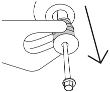
1 Use a spanner or socket to unscrew and remove all four transit bolts at the back of the washer.
2 To remove the bolt, grommet and white plastic spacers, pull on the black rubber grommets.
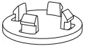
3 Cover the transit bolt holes with the plastic plugs delivered with the washer. Push to plug into place.
LEVELLING THE WASHER
It is IMPORTANT to level the washer. Having a level washer set up in its cavity will ensure best performance for spinning, minimising noise, vibrations and wear and tear on the washer.
1 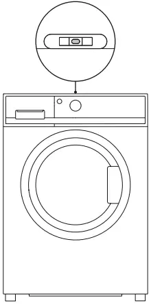
Move the washer into its final position allowing for required clearances.
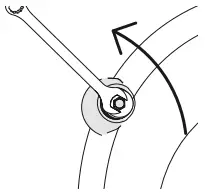
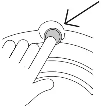
Level the washer side to side:
Place the level on the centre front of the washer. Pull the washer out, loosen the lock nut (using the spanner provided) and wind the feet up or down until the washer is level side to side.
2 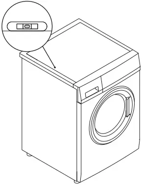
Level the washer front to back:
Place the level on the left side, in line with the centre of the washer. Adjust the front left foot and then the right foot until the washer is level.
There should be equal weight on both front feet.
3 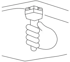
Using the spanner provided, tighten the lock nuts against the base of the washer to lock the feet in position.
Move and centre the washer into its final position within the cavity, ensuring recommended clearances.
Recheck the washer is level, front to back and side to side. Repeat the above steps if required.
COMPLETE INSTALLATION
- Turn on the water and check all hose connections for leaks. Make sure there are no kinks in the hose(s). Check the hose connections for leaks again after 24 hours.
- Uncoil power cord, remove and discard the plastic pin cover, and plug into wall socket.
- Connect the appliance to an earthed outlet protected by a fuse of suitable capacity.
Test cycle
Your washer must be correctly installed before use. To check the installation and operation of the washer follow the steps below:
1 
Press POWER ![]() to activate your washer.
to activate your washer.
2 
Select a QUICK cycle. Ensure the drum is empty and the door closed.
3 
Press ![]() to start.
to start.
4
Wait until you see water in the bottom of the drum.
5 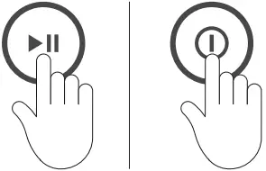
Press ![]() to stop the cycle, then press
to stop the cycle, then press
POWER ![]() to turn the washer off.
to turn the washer off.
6 
Activate the washer again by pressing
POWER ![]() , select SPIN cycle.
, select SPIN cycle.
Press ![]() to begin the spin.
to begin the spin.
Check the drain hose is firmly secured to the standpipe or tub, or spigot.
Observe that the washer pumps out the water, and spins.
The washer will beep to signal the end of the cycle. Any faults will be displayed on the screen, refer your user guide.
If there are any problems, you must address these before proceeding with normal use. The washer will automatically turn off at the end of the cycle if there are no problems.
If the washer is moved or tipped for any reason, it must be completely re-installed following the steps in this installation guide. This includes running a test cycle to check for any problems.
*Your washer control panel may differ from that shown.
INSTALLER CHECKLIST
TO BE COMPLETED BY THE INSTALLER
… Have the packaging and transit bolts and rods been removed?
… Is the washer correctly levelled, feet are extended and cabinet corners are clear of the floor?
… Is the drain hose threaded through the hose guide ‘U bend’ (with no more than 20mm extended) and hooked into your standpipe or tub, or attached to a spigot?
… Have the taps been turned on?
… Is the hot hose connected to the hot valve marked ‘H’?
… Is the cold hose connected to the cold valve marked ‘C’?
… Has the power cord been connected to an appropriate power supply and the power turned on?
… Have you performed the test cycle?.
… Complete a DRUM CLEAN cycle with a half-load amount of detergent and without a load to remove any residues remaining in the washer from the manufacturing process.
Complete and keep for safe reference:
Model _____________________________
Serial no. _____________________________
Purchase date _____________________________
Purchaser _____________________________
Dealer address _____________________________
Installer’s name _____________________________
Installer’s signature _____________________________
Installation company _____________________________
Installation date _____________________________
SPARE PARTS
| SPARE PARTS* | PART NO. |
| Hose(s) inlet long (2 m) | 422680P |
| Hose(s) inlet large bore | 426123P |
*Available from your Fisher & Paykel dealer or a Fisher & Paykel trained and supported service technician
© Fisher & Paykel Appliances 2022. All rights reserved.
The models shown in this guide may not be available in all markets and are subject to change at any time.
The product specifications in this guide apply to the specific products and models described at the date of issue. Under our policy of continuous product improvement, these specifications may change at any time.
For current details about model and specification availability in your country, please go to our website or contact your local Fisher & Paykel dealer.
430291B 05.22


