SILICON LABS UG205 CP2102N-EK Kit User Guide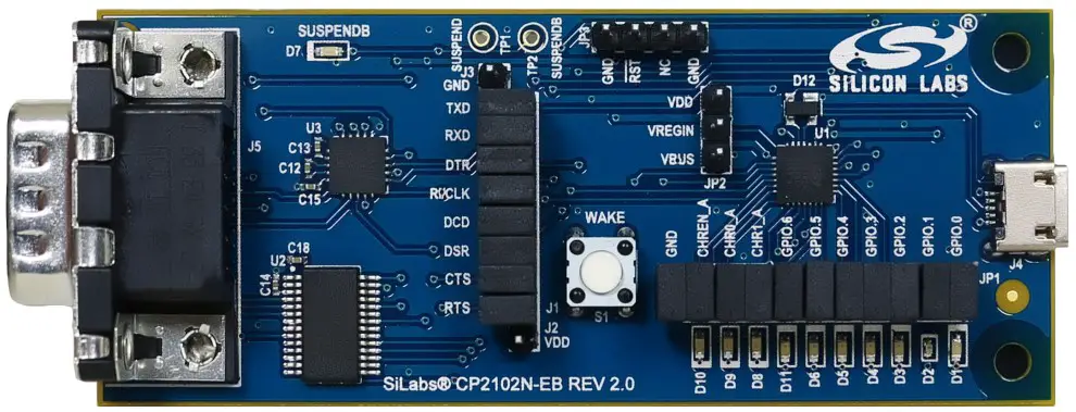
The CP2102N-EK kit is designed to showcase the various features of the CP2102N USBXpress® devices.
These highly-integrated USB-to-UART bridge controllers provide a simple solution for updating RS-232 designs to USB using a minimum of components and PCB space. By eliminating the need for complex firmware and driver development, the CP2102N devices enable quick USB connectivity with minimal development effort
The kit includes the following:
- CP2102N USB-to-UART Bridge Evaluation Board
- 1 x serial cable
- Getting Started card
- 1 x micro USB cable
KEY FEATURES
- CP2102N USB-to-UART Bridge
- Headers for easy access to GPIO, UART, or Battery Charger Detect pins
- RS-232 Transceiver and DB9 connector
- SUSPENDb LED, GPIO LEDs
- Remote Wakeup pushbutton for waking host PC
- 3 Mbaud TXD/RXD RS-232 transceivers

Getting Started
- Download and Install the Latest Virtual COM Port (VCP) Drivers. The Virtual COM Port (VCP) drivers enable the CP2102N to appear as a standard COM port. Download the latest version of drivers from the Silicon Labs website:
http://www.silabs.com/vcpdrivers In most cases, select the default option without serial enumeration. - Set Up Your Kit.
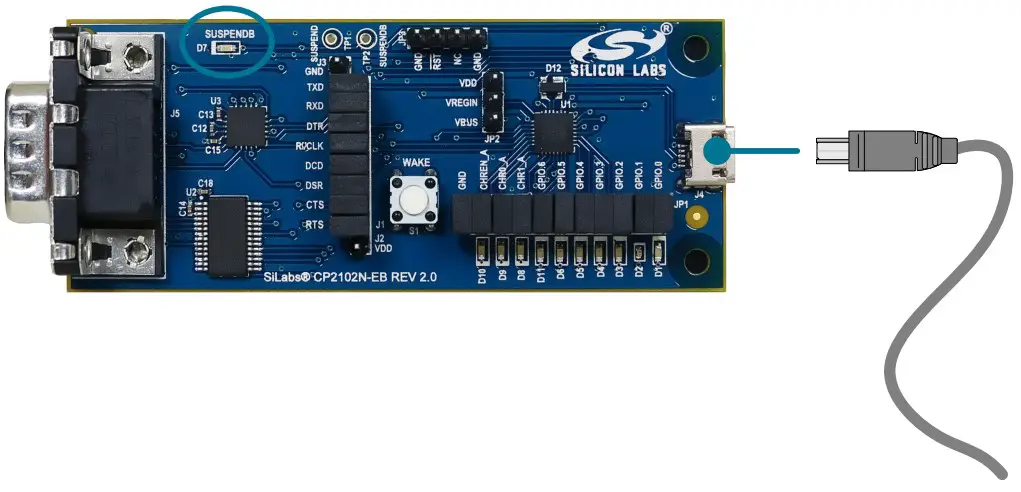
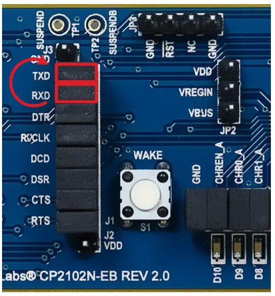
a. Provide power to the board by connecting the USB connector to the PC using the provided USB cable. When a connection has been established successfully, the LED (marked in the picture) lights up.
b. Connect the serial cable to an external device or use the J1 header to jumper UART signals to the external device.
- Detect Your Device.
The CP2102N device will appear as a COM port in Device Manager in Windows. As a virtual COM port, the CP210x functions identically to a real COM port from the reference point of both the host application and the serial device, and it can support serial device control requests defined in the Microsoft Win32® Communications API.
- Set up a Loop-Back Test.
Rotate the jumpers on the CP210x 7 RX and TX pins to tie RX and TX together and perform a loop back test.
- Send and Receive Some Data
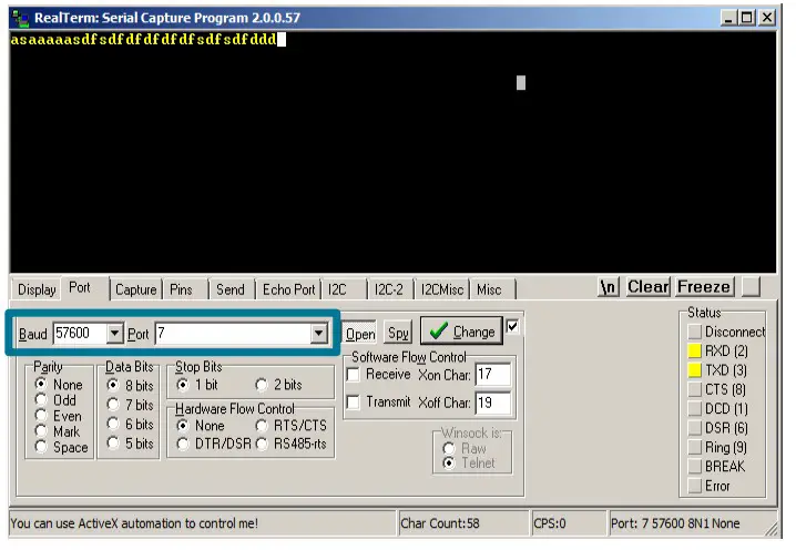
a. In Windows, open a serial terminal program (downloaded separately, RealTerm pictured) to verify the CP2102N UART functionality.
b. Set the baud rate and select the COM port from Device Manager.
c. Type in the transmit area. The characters should echo back after looping through the CP2102N TXD and RXD pins.
- Utilize the Available Resources
The next section includes additional resources available for the device, including documentation and application notes.
Relevant Documentation
The following Application Notes are applicable to CP2102N devices:
- AN721: CP210x Device Customization Guide — This application note guides developers through the configuration process of USBXpress devices using Simplicity Studio [Xpress Configurator].
- AN220: USB Driver Customization — This document and accompanying software enable the customization of the CP210x Virtual COM Port (VCP) and USBXpress drivers.
- AN197: Serial Communications Guide for CP210x — This document describes recommendations for communicating with USBXpress CP210x devices using the Virtual COM Port (VCP) driver.
- AN976: Migrating from a CP2102 to a CP2102N — This document guides developers on how to migrate existing systems using the CP2102 to the CP2102N.
- AN169: USBXpress Programmer’s Guide — This application note provides recommendations and examples for developing using the USBXpress direct-access driver.
- AN807: Recertifying a Customized Windows HCK Driver Package — This document describes the WHQL certification process required for customized drivers.
- AN223: Runtime GPIO Control for CP210x — This document describes how to toggle GPIO pins from the USB host.
Application Notes can be accessed on the Silicon Labs website (www.silabs.com/interface-appnotes) or in Simplicity Studio using the [Getting Started]>[Application Notes] area of the launcher.
Device Customization
Device customization for the CP2102N is done through Xpress Configurator, which isavailable in Simplicity Studio:
http://www.silabs.com/simplicity
The Simplicity Studio software package contains all the tools, drivers, configuration software, and documentation needed to use theCP2102N USB-to-UART Bridge Evaluation Board.
After downloading the latest version of Simplicity Studio and installing the software:
- Install the CP210x Virtual COM Port Driver during the software setup steps, if it’s not already installed. This action can always be accessed through the [Setup Tasks] tile in the [Resources] section.
- Click the [Refresh detected hardware] button.
- Select [CP2102N] under [Detected Hardware]. On the board, a successful USB connection is established when the SUSPENDB LED (D7) turns on.
- Click the [Xpress Configurator] tile to open Xpress Configurator and customize the device.
Documentation for each of the customization options is provided within Xpress Configurator. More information on each of these options can be found in AN721: CP210x Device Customization Guide, which is available on the Silicon Labs website (www.silabs.com/interface-appnotes) or within Simplicity Studio using the [Application Notes] tile.
Driver Options and Software Interface
Virtual COM Port (VCP) Driver
CP2102N devices are pre-programmed with a VID of 0x10C4 and PID of 0xEA60. This VID and PID combination matches the Virtual COM Port (VCP) driver. With this driver, the CP2102N will appear as a COM port and can be accessed using any terminal program or custom-written software. Install the VCP driver as part of the Simplicity Studio installation or download it directly from the Silicon Labs website (www.silabs.com/interface-software).
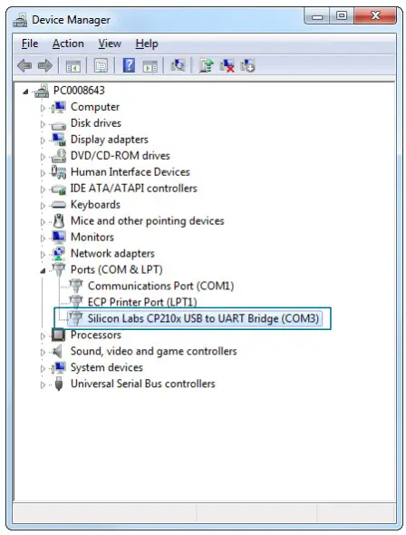
If the Virtual COM Port (VCP) drivers are used, the CP2102N will appear as a COM port in the Device Manager, as shown in the figure below. The CP2102N will always use the lowest available COM port for operation. For instance, if COM ports 1 and 2 are in use by other peripherals and applications, the CP2102N will use COM 3.
The CP2102N functions identically to a COM port from the reference point of both thehost application and the serial device, and it can support serial device control requests defined in the Microsoft Win32® Communications API. Examples for how to communicate with the device as a serial COM port are included in AN197: Serial Communications Guide for CP210x or in the SDK.
Figure 4.1. CP2102N in Device Manager — VCP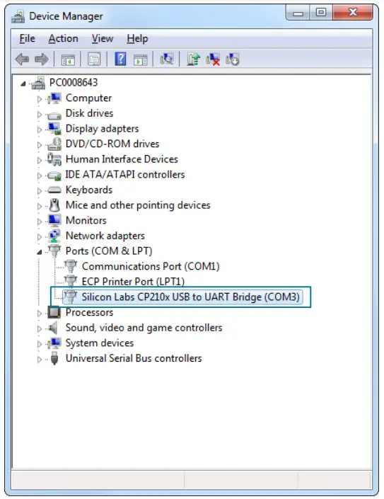
USBXpress Driver
An alternative driver is the USBXpress® direct-access driver, which is also available on the Silicon Labs website (www.silabs.com/interface-software). Rather than appearing as a COM port, software can use a simple, high-level Application Program Interface (API) to provide access to CP2102N for complete USB connectivity. No USB protocol or host device driver expertise is required. The USBXpress Development Kit includes Windows device drivers, Windows device driver installer, and host interface function library (host API) provided in the form of a Windows Dynamic Link Library (DLL). See Application Note AN169: USBXpress Programmer’s Guide for detailed information on using the USBXpress drivers.
If the USBXpress drivers are used, the CP2102N will appear as a USB USBXpress device as shown in the figure below. Examples for how to communicate with the device using the USBXpress interface are included in AN169: USBXpress Programmer’s Guide.
Figure 4.2. CP2102N in Device Manager — USBXpress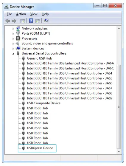
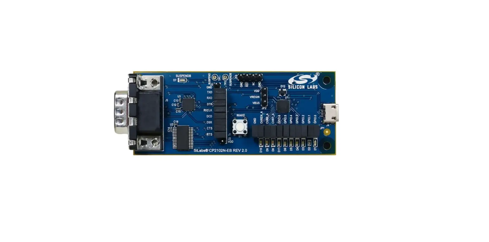
Hardware Overview
The CP2102N Evaluation Kit includes an evaluation board with a CP2102N device pre installed for evaluation and preliminary software development. Numerous input/output (I/O) connections are provided to facilitate prototyping using the evaluation board. Refer to the figure below for the locations of the various I/O connectors.
Note: There is a restriction on the maximum VBUS voltage. Take care not to connect the board to USB (and thus VBUS to the USB 5V supply) while VDD is shorted to VREGIN on JP2 without first externally powering VDD via J2. See the Typical Connection Diagrams chapter in the device data sheet for more information.
Table 5.1. CP2102N Evaluation Board Component Overview
| Component | Description |
| D7 | SUSPENDb indicator LED |
| D1 | GPIO.0 indicator LED |
| D2 | GPIO.1 indicator LED |
| D3 | GPIO.2 indicator LED |
| D4 | GPIO.3 indicator LED |
| D5 | GPIO.4 indicator LED |
| D6 | GPIO.5 indicator LED |
| D11 | GPIO.6 indicator LED |
| D8 | CHR1 indicator LED |
| D9 | CHR0 indicator LED |
| D10 | CHREN indicator LED |
| J1 | UART signal access connector |
| J2 | VDD header |
| J3 | Ground header |
| J4 | USB connector for USB interface |
| J5 | DB9 connector for RS232 interface |
| JP1 | Battery Charger Detect and GPIO access connector |
| JP2 | Power pins (VDD, VREGIN, and VBUS) access connector. This connector can select between a bus-powered configuration (VBUS connected to VREGIN) or self-powered configuration (VREGIN connected to VDD with VDD powered externally). |
| JP3 | Ground and RSTb header |
Figure 5.1. CP2102N Evaluation Board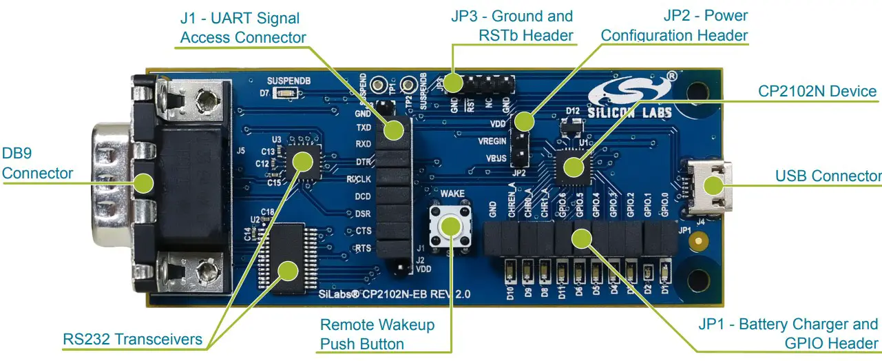
USB Interface (J4)
A Universal Serial Bus (USB) connector (J4) is provided to facilitate connections to the USB interface on the CP2102N. See the table below for the USB pin definitions.
Note: There is a restriction on the maximum VBUS voltage. Take care not to connect the board to USB (and thus VBUS to the USB 5V supply) while VDD is shorted to VREGIN on JP2 without first externally powering VDD via J2. See the Typical Connection Diagrams chapter in the device data sheet for more information.
Table 5.2. USB Connector Pin Descriptions
| Pin Number | Description |
| 1 | VBUS |
| 2 | D- |
| 3 | D+ |
| 4 | GND (Ground) |
UART Interface (J1 and J5)
A RS232 transceiver circuit and DB9 connector (J5) are provided on the evaluation board to connect the CP2102N to external serial devices.
Table 5.3. RS232 Pin Descriptions
| Pin | Signal | CP2102N Direction | Description |
| 1 | DCD | Output | Data Carrier Detect |
| 2 | RXD | Input | Receive Data |
| 3 | TXD | Output | Transmit Data |
| 4 | DTR | Input | Data Terminal Ready |
| 5 | GND | — | Ground |
| 6 | DSR | Input | Data Set Ready |
| 7 | RTS | Output | Request to Send |
| 8 | CTS | Input | Clear to Send |
| 9 | RI | Input | Ring Indicator |
The J1 connector is provided to facilitate direct access to the CP2102N UART signals. Shorting blocks on J1 are required to connect the UART signals to the J5 DB9 connector.
Table 5.4. J1 Pin Descriptions
| Pins | Signal | CP2102N Direction | Description |
| 15-16 | TXD | Output | Transmit Data |
| 13-14 | RXD | Input | Receive Data |
| 11-12 | DTR | Output | Data Terminal Ready |
| 9-10 | RI / CLK | Input / Output | Ring Indicator / Clock Output |
| 7-8 | DCD | Input | Data Carrier Detect |
| 5-6 | DSR | Input | Data Set Ready |
| 3-4 | CTS | Input | Clear to Send |
| 1-2 | RTS | Output | Request to Send |
Note: To measure power of the CP2102N and achieve lowest power consumption, remove R22 and populate R12. This allows the Sipex RS232 transceiver to enter shutdown mode when it is not receiving RS232 signals. The transceiver leaves shutdown mode only when it receives RS232 signals (+-3V) on RxIN, not digital signals on TxIN.
Battery Charger Detect and GPIO (JP1)
The JP1 header provides access to the CP2102N Battery Charger Detect and GPIO pins. See the table below for the JP1 pin descriptions.
The row of LEDs next to the JP1 header serves as the indicators for each of the functions assigned to the GPIO pins. Removing a JP1 header shorting block disconnects the LED from the corresponding pin and CP2102N signal.
Note: The CP2102N Battery Charger Detect LEDs are connected in an active-high configuration, while the GPIO pin LEDs are connected in an active-low configuration.
Table 5.5. JP1 Pin Descriptions
| Pins | Signal | CP2102N Direction | Description |
| 21-22 | GND | — | Ground |
| 19-20 | CHREN | Output | Enable charging circuit (100 mA) |
| 17-18 | CHR0 | Output | Enable charging circuit (500 mA) |
| 15-16 | CHR1 | Output | Enable charging circuit (1.5 A) |
| 13-14 | GPIO.6 | Input / Output | General Purpose I/O 6 |
| 11-12 | GPIO.5 | Input / Output | General Purpose I/O 5 |
| 9-10 | GPIO.4 | Input / Output | General Purpose I/O 4 |
| 7-8 | GPIO.3 | Input / Output | General Purpose I/O 3 |
| 5-6 | GPIO.2 | Input / Output | General Purpose I/O 2 |
| 3-4 | GPIO.1 | Input / Output | General Purpose I/O 1 |
| 1-2 | GPIO.0 | Input / Output | General Purpose I/O 0 |
Schematics and BOM
Board Files
The schematics and bill of materials (BOM) for the CP2102N USB-to-UART Bridge Evaluation Board are available through Simplicity Studio when the kit documentation package has been installed. To access these documents, click the [Kit Documentation] tile after selecting the device in the left pane.
Board Revision History
2.1 — Initial production revision.
Revision 2.1 Boards
These boards do not currently have any known issues.
Revision History
Revision 0.2
June 17th, 2016
Updated instructions for Simplicity Studio v4.
Revision 0.1
April 19th, 2016
Initial revision.
IoT Portfolio
www.silabs.com/IoT
SW/HW
www.silabs.com/simplicity
Quality
www.silabs.com/quality
Support and Community
community.silabs.com
Disclaimer
Silicon Laboratories intends to provide customers with the latest, accurate, and in-depth documentation of all peripherals and modules available for system and software implementers using or intending to use the Silicon Laboratories products. Characterization data, available modules and peripherals, memory sizes and memory addresses refer to each specific device, and “Typical” parameters provided can and do vary in different applications. Application examples described herein are for illustrative purposes only. Silicon Laboratories reserves the right to make changes without further notice and limitation to product information, specifications, and descriptions herein, and does not give warranties as to the accuracy or completeness of the included information. Silicon Laboratories shall have no liability for the consequences of use of the information supplied herein. This document does not imply or express copyright licenses granted hereunder to design or fabricate any integrated circuits. The products are not designed or authorized to be used within any Life Support System without the specific written consent of Silicon Laboratories. A “Life Support System” is any product or system intended to support or sustain life and/or health, which, if it fails, can be reasonably expected to result in significant personal injury or death. Silicon Laboratories products are not designed or authorized for military applications. Silicon Laboratories products shall under no circumstances be used in weapons of mass destruction including (but not limited to) nuclear, biological or chemical weapons, or missiles capable of delivering such weapons.
Trademark Information
Silicon Laboratories Inc.® , Silicon Laboratories®, Silicon Labs®, SiLabs® and the Silicon Labs logo®, Bluegiga®, Bluegiga Logo®, Clockbuilder®, CMEMS®, DSPLL®, EFM®, EFM32®, EFR, Ember®, Energy Micro, Energy Micro logo and combinations thereof, “the world’s most energy friendly microcontrollers”, Ember®, EZLink®, EZRadio®, EZRadioPRO®, Gecko®, ISOmodem®, Precision32®, ProSLIC®, Simplicity Studio®, SiPHY®, Telegesis, the Telegesis Logo®, USBXpress® and others are trademarks or registered trademarks of Silicon Laboratories Inc. ARM, CORTEX, Cortex-M3 and THUMB are trademarks or registered trademarks of ARM Holdings. Keil is a registered trademark of ARM Limited. All other products or brand names mentioned herein are trademarks of their respective holders.
Silicon Laboratories Inc.
400 West Cesar Chavez
Austin, TX 78701
USA
Downloaded from Arrow.com.