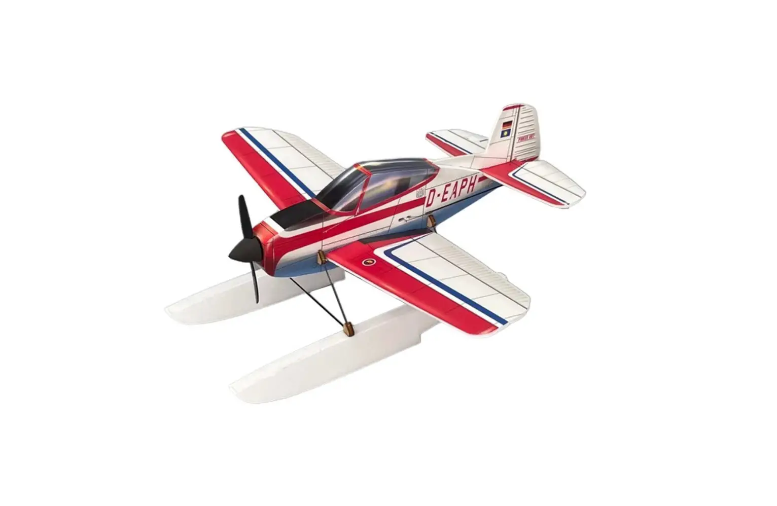
MinimumRC 4CH 320mm Smallest Airplane Instruction Manual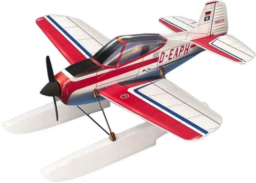
Important notification
- The model is supplied with UFO and 502 glue. UFO is for bonding foam parts, and 502 for bonding wood, carbon fiber and metal parts. 502 glue will cause serious corrosion to foam parts.
- Please wait for the glue to dry and solidify in each installation step before the next installation.
- Please avoid using flame to heat the heat shrinkable tube on the model. Electric iron shall be used for heating.
- Please use razor blade to remove the parts from the plate. Do not tear the parts by force.
Assembly Instructions
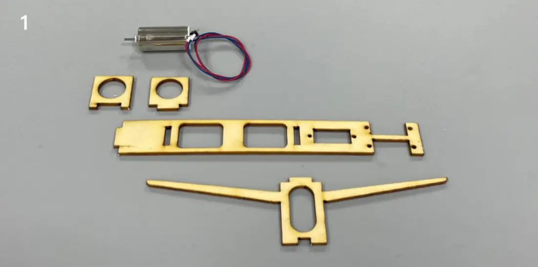
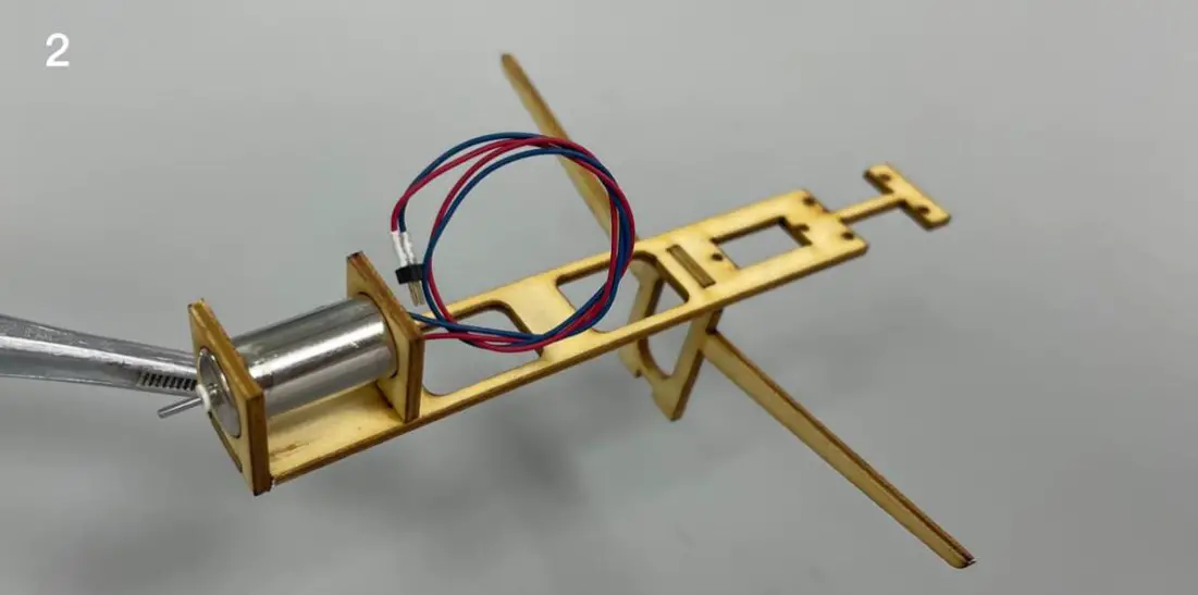
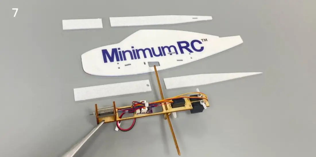
- Fuselage internals.

- Bond the inner structure of the fuselage with 502 glue.
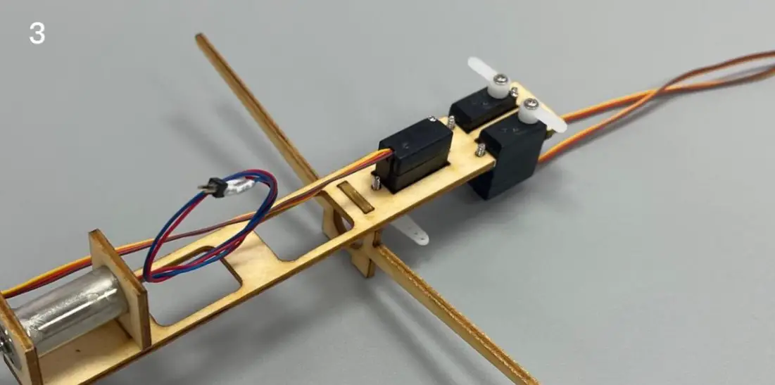
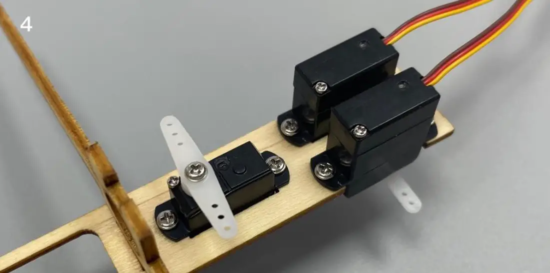
- Connect the servos to a powered receiver. Bind the receiver with your transmitter to make the servos arms return to their neutral point. Test whether the servos are working normally, and install the servo arms according to the position shown in the picture.
Note: Please make sure that the servos have been tested and installed in strict accordance with the following picture. After assembling the model, it will be not able to adjust. - (bottom view) the three servos are installed and fixed under the plywood board.
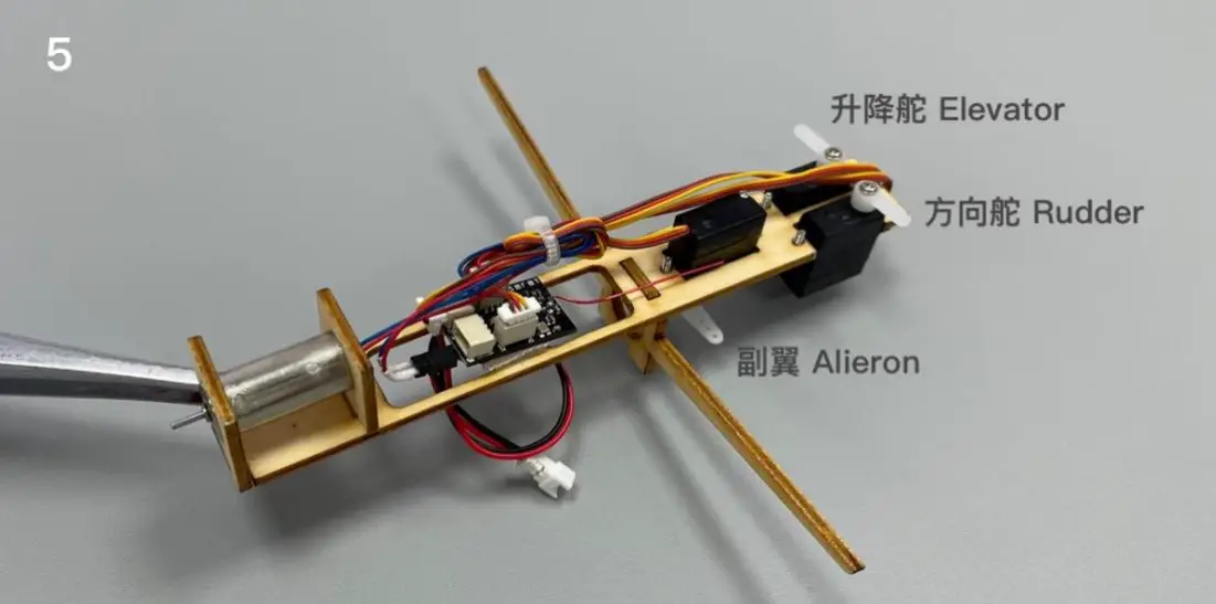
- Connect the receiver to the motor, install the propeller and test whether the rotation direction of the motor is correct. If the motor is reversed, reverse the motor line. Test whether the corresponding relationship between the three steering gears and the transmitter channel is correct (as shown in the figure). After the test, fix the receiver with Velcro and tie the cable.
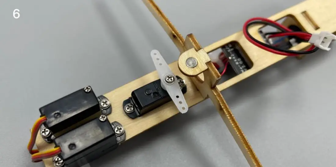
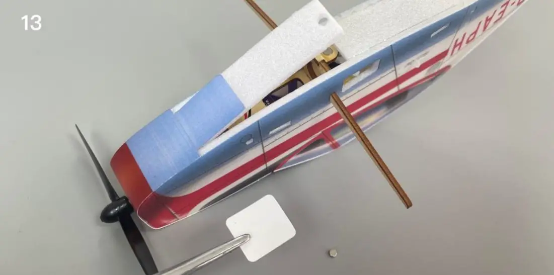
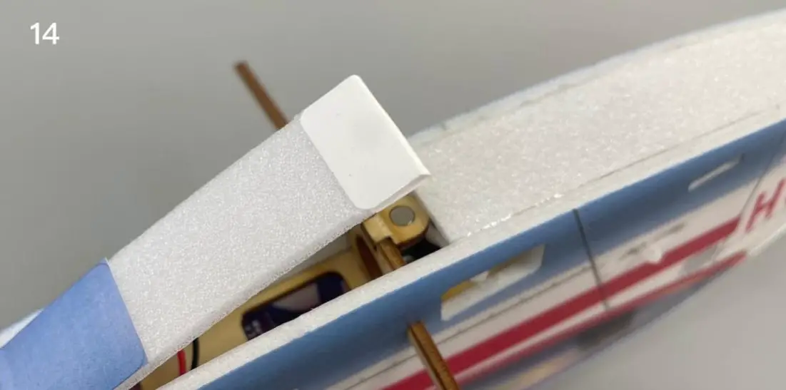
- Install magnet base & magnet.
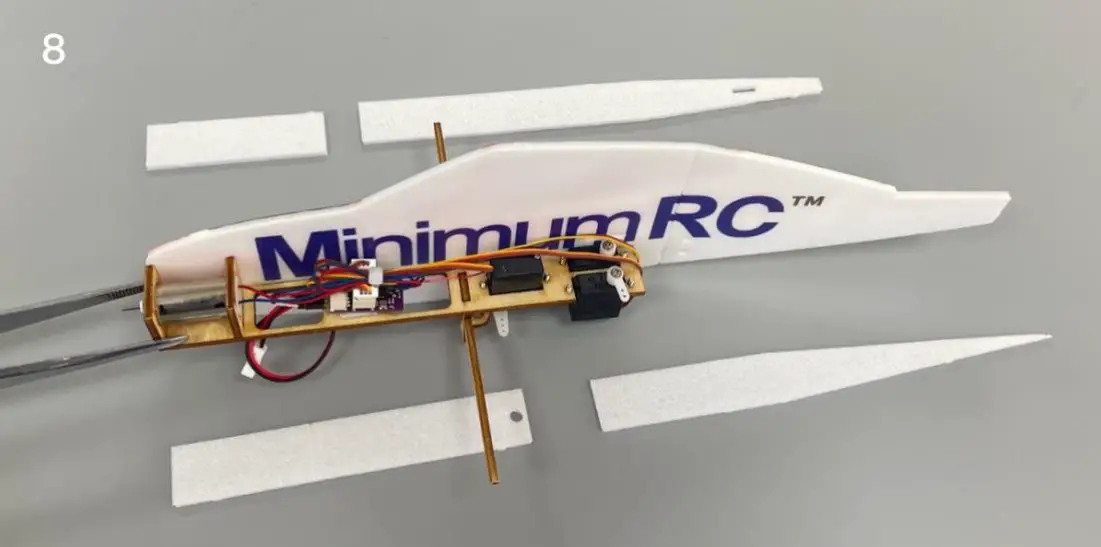
- Align the scribed line on the inner side of the fuselage and fix the wooden structure with glue.
- Align the scribed line on the inner side of the fuselage and fix the wooden structure with glue.
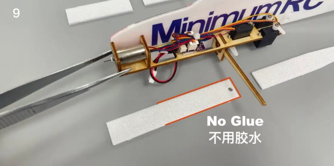
- Note: the position shown in the figure is the battery cover plate that can be opened and closed. No glue shall be applied to the area marked by the red line.
- Press the top plate and bottom plate of the fuselage and bend them into the corresponding shape of the fuselage contour. Fix the top plate and bottom plate of the fuselage with glue.
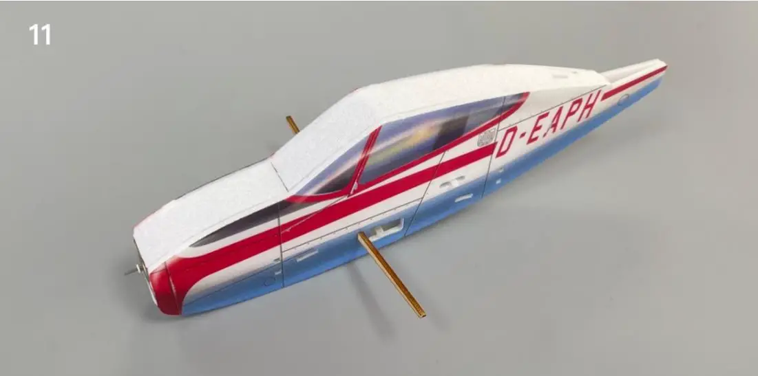
- Combine the fuselage.
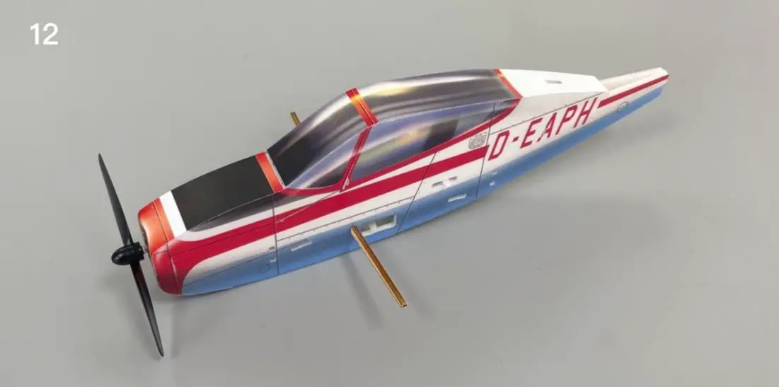
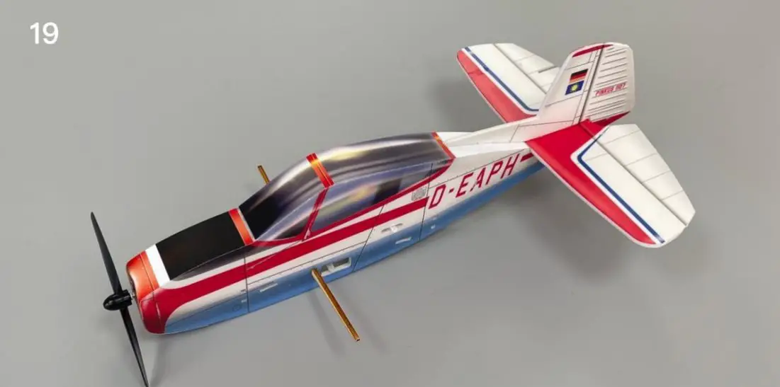
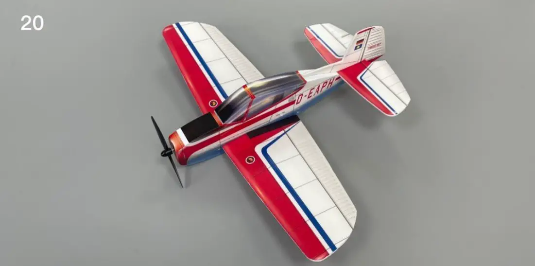
- Paste the fuselage sticker and install the propeller.
- Fix the battery cover magnet with glue and cover it with stickers
- The battery cover can be opened, and can be adsorbed in the closed position by magnet.
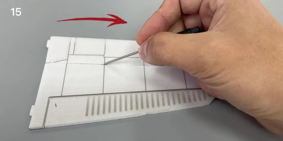
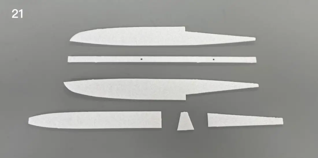
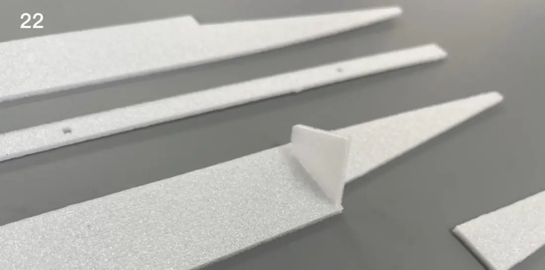
- Use the end of a carbon fiber rod to score through the half-cut line of the wing surface.
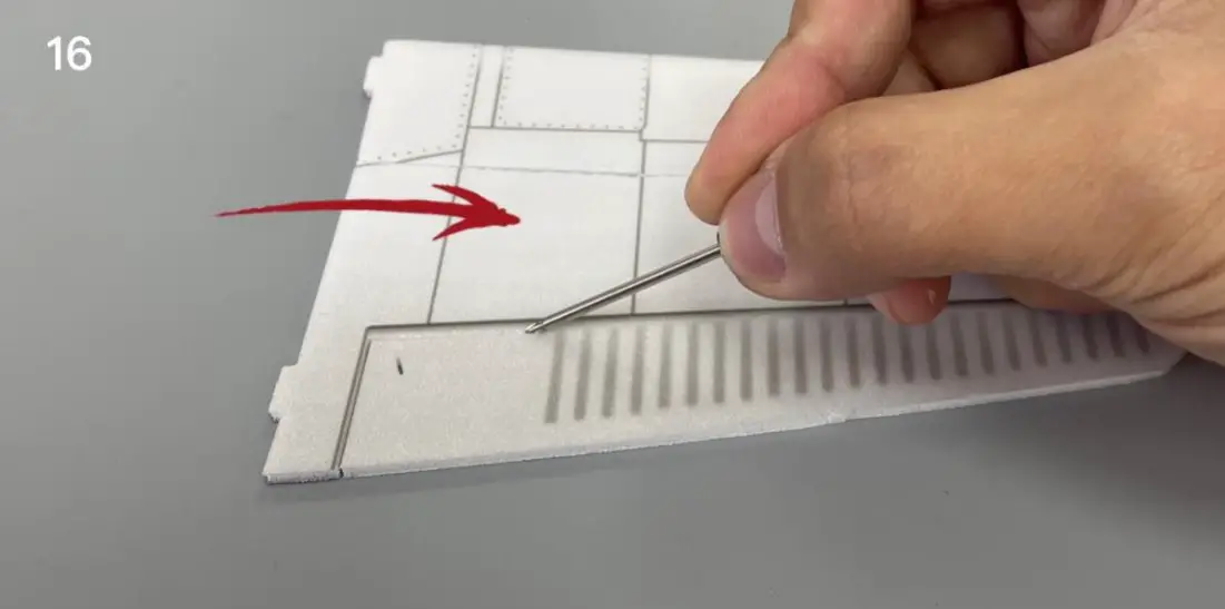
- Use the end of a carbon fiber rod to score through the aileron half-cut line of the wing surface.
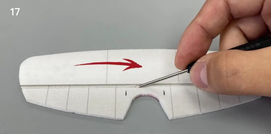
- Use the end of a carbon fiber rod to score through the half -cut line of the tail surface.
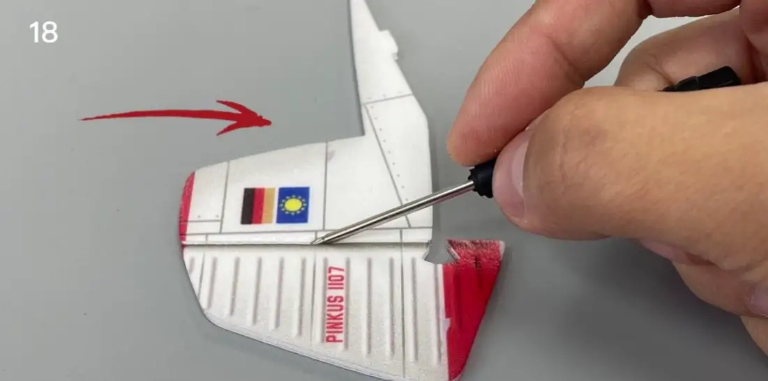
- Use the end of a carbon fiber rod to score through the half -cut line of the rudder surface.
- Install the tail.
- Attach the wings to the fuselage.
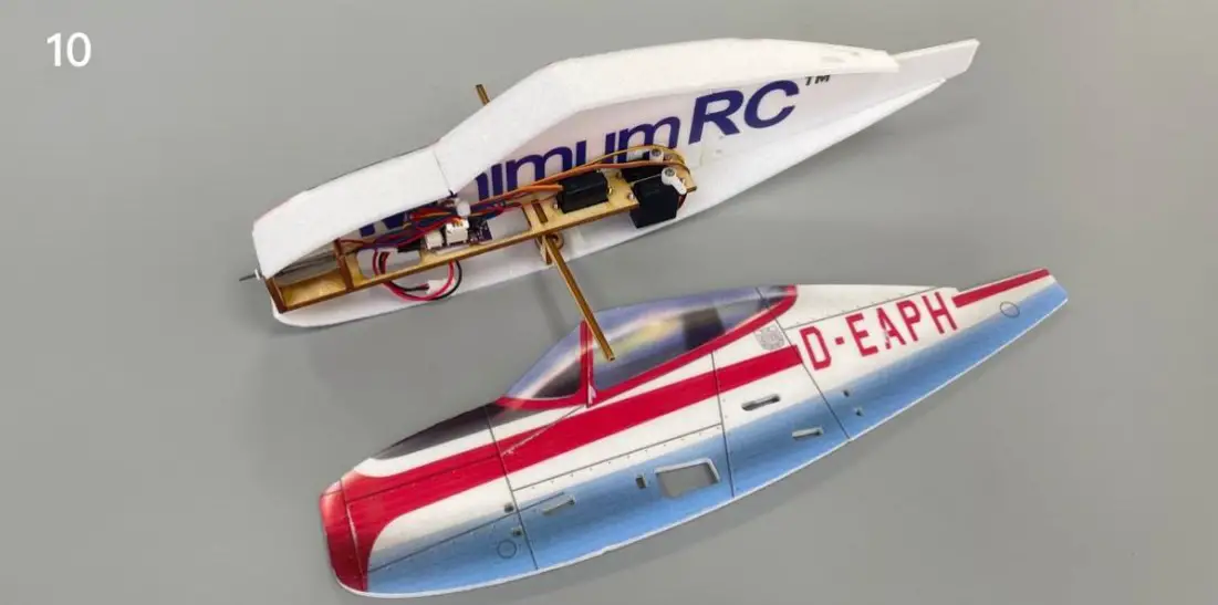
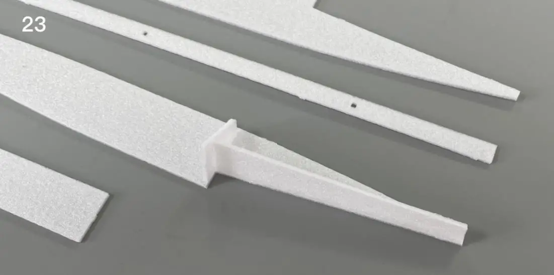
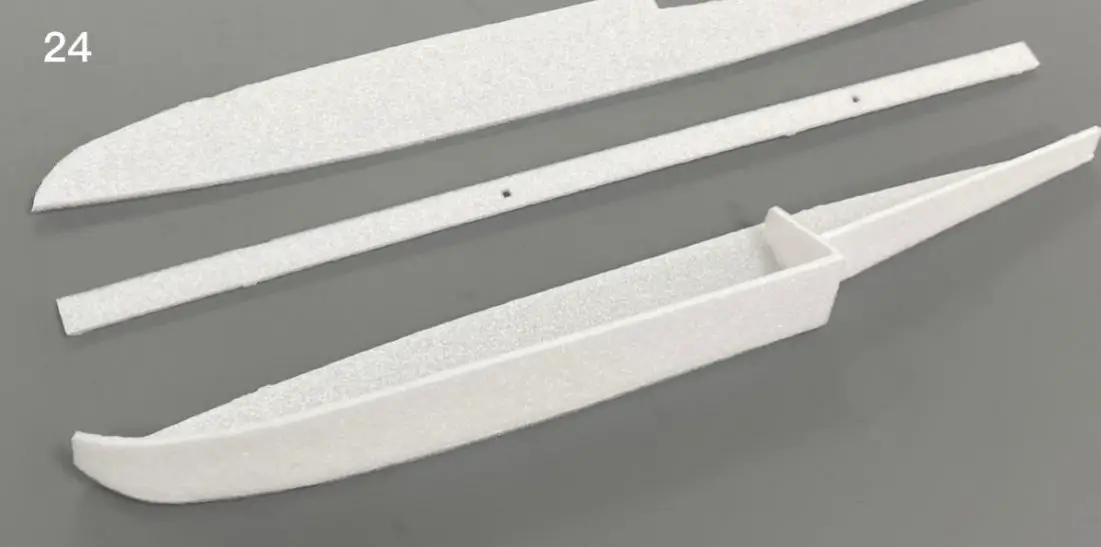
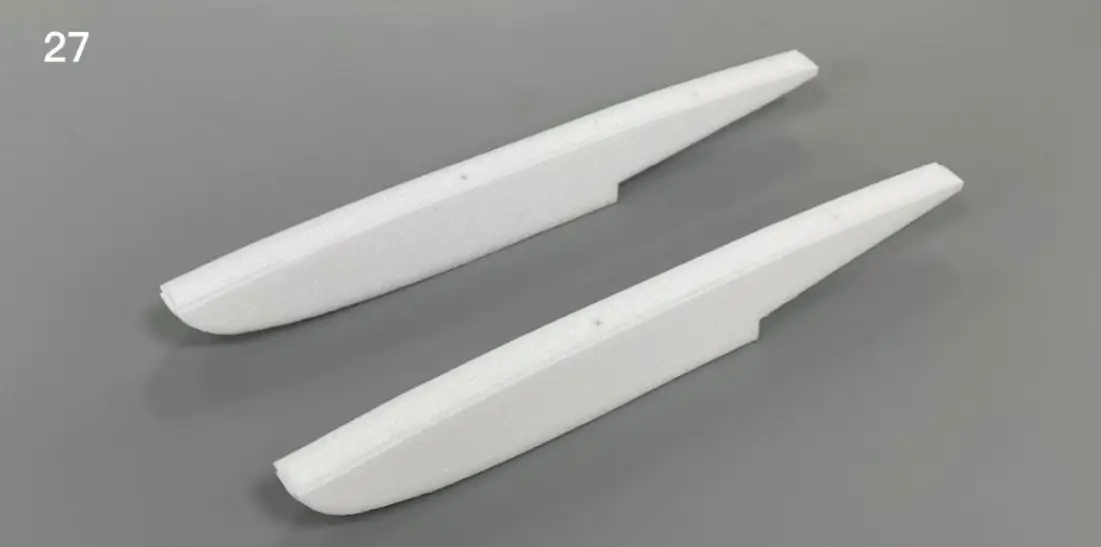
- Float parts.
- Parts
- Parts
- Parts
- Parts
- Parts
- Parts
- Parts
- Parts
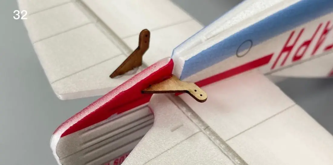
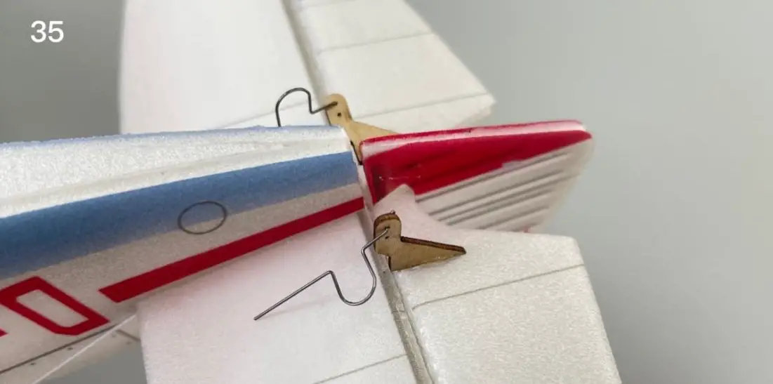
- Install aileron control horns.
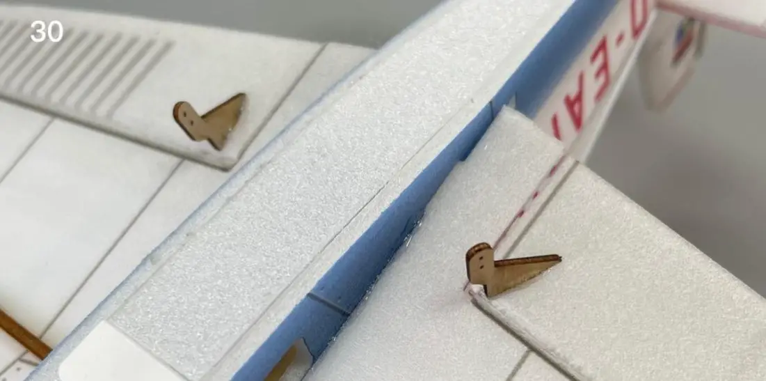
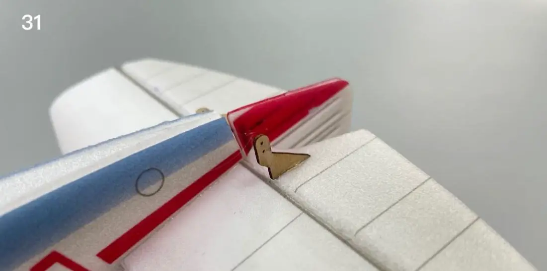
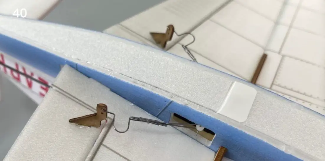
- Install elevator control horns.
- Install elevator control horns.
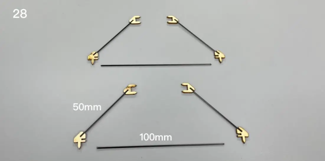
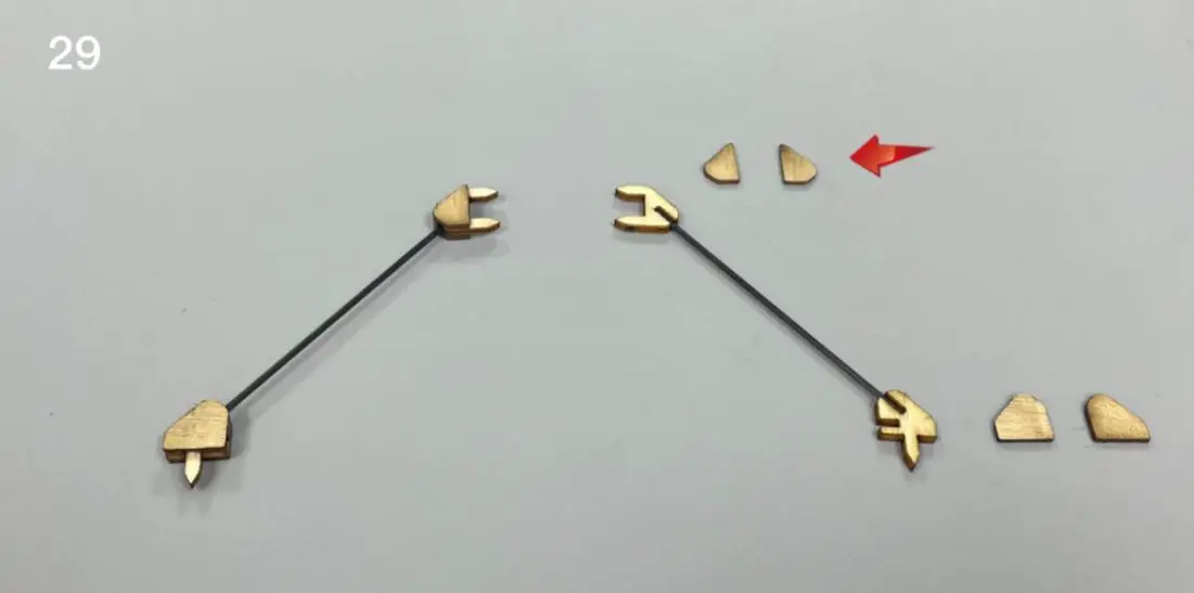
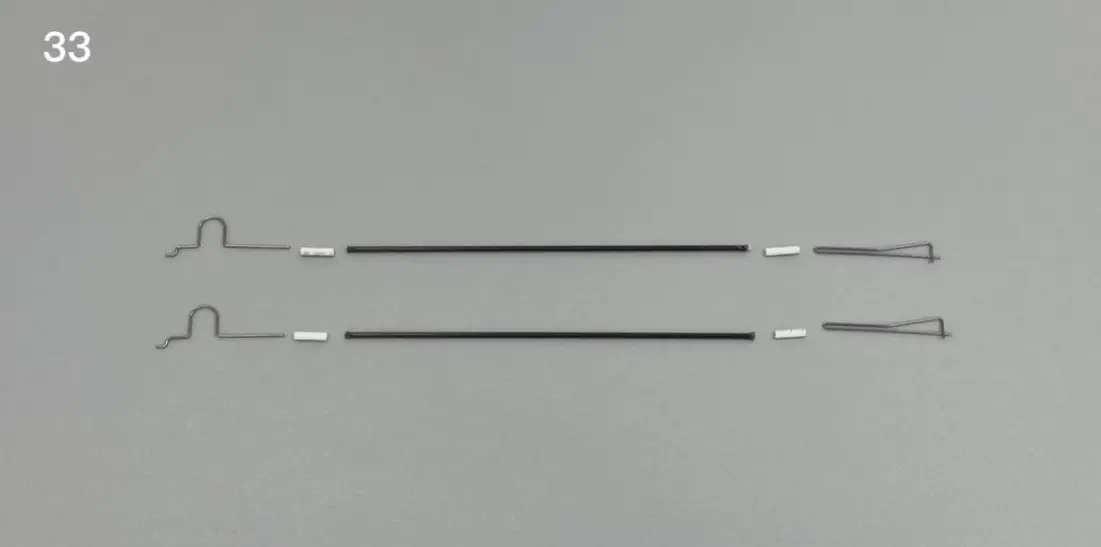
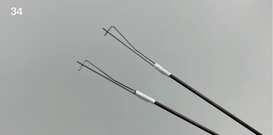
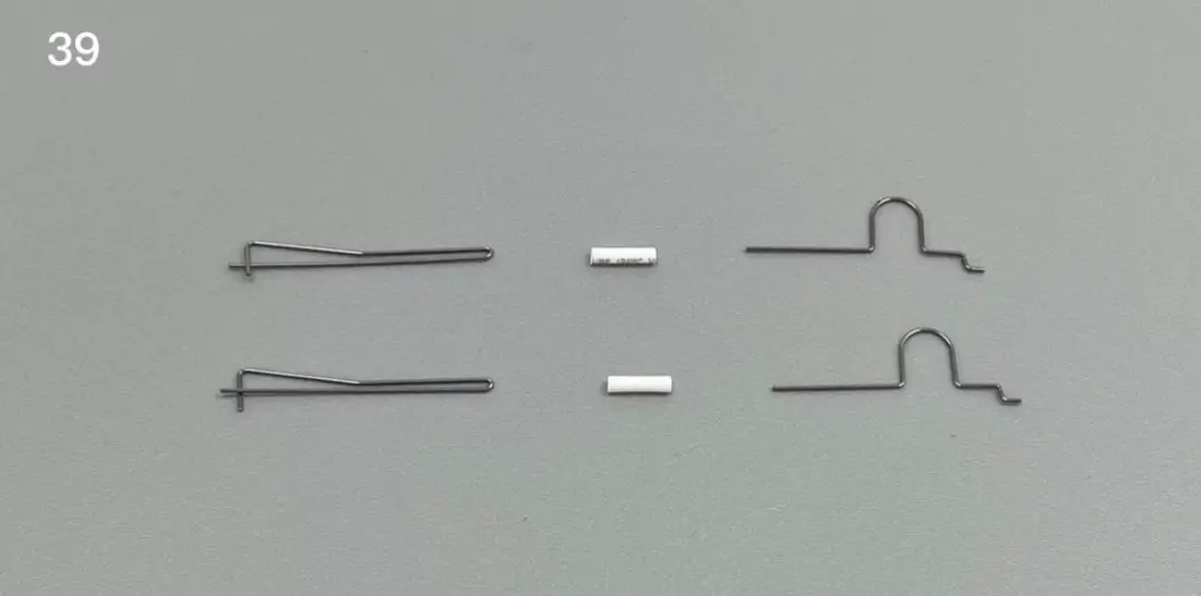
- Use heat shrinkable tube to connect tail push rod and steel wire clip.
- Use heat shrinkable tube to connect the pull rod and wire clip, then use glue to fix them.
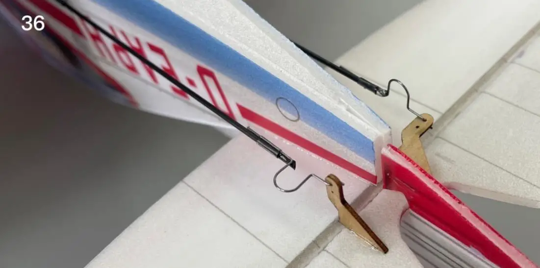
- Attach the steel wire hook to the control horns.
- Cut the carbon rod to proper length and connect the wire hooks with heat shrinkable tubes.
- Connecting
- Connecting
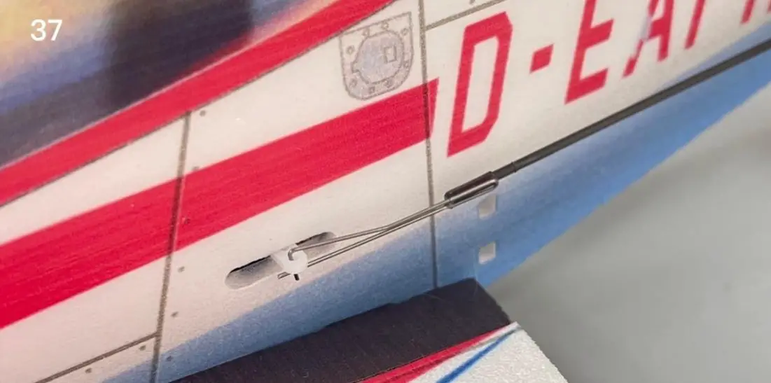
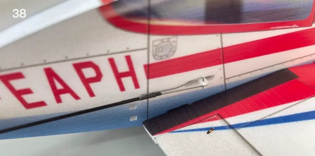
- Use heat shrinkable tube to connect aileron steel wire clips.
- Attach the steel wire clip to the aileron servo arm. Connect the wires with heat shrinkable tubes.
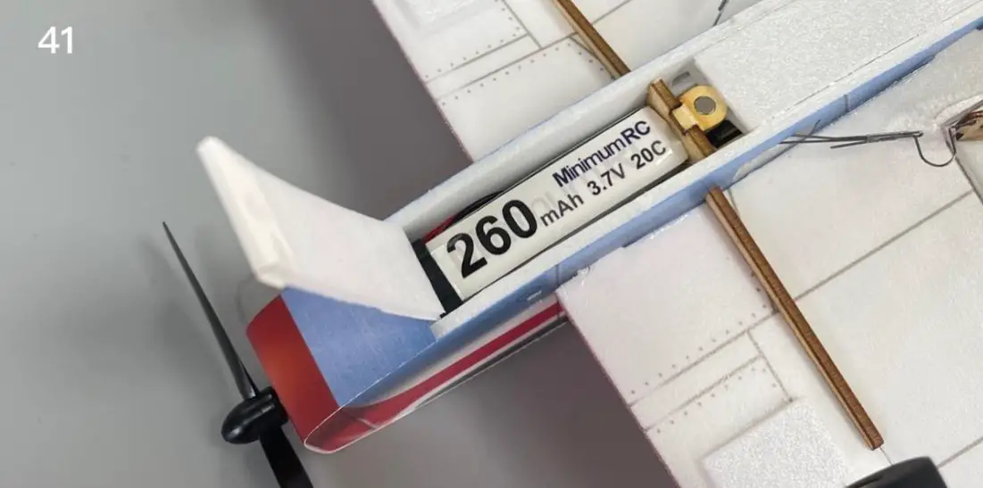
- The battery is directly placed in the battery compartment.
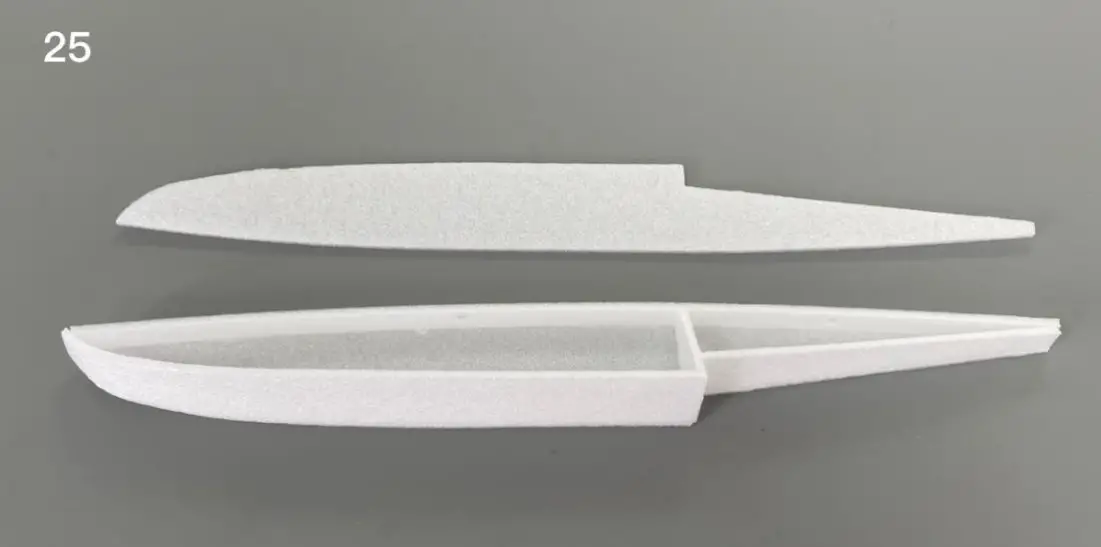
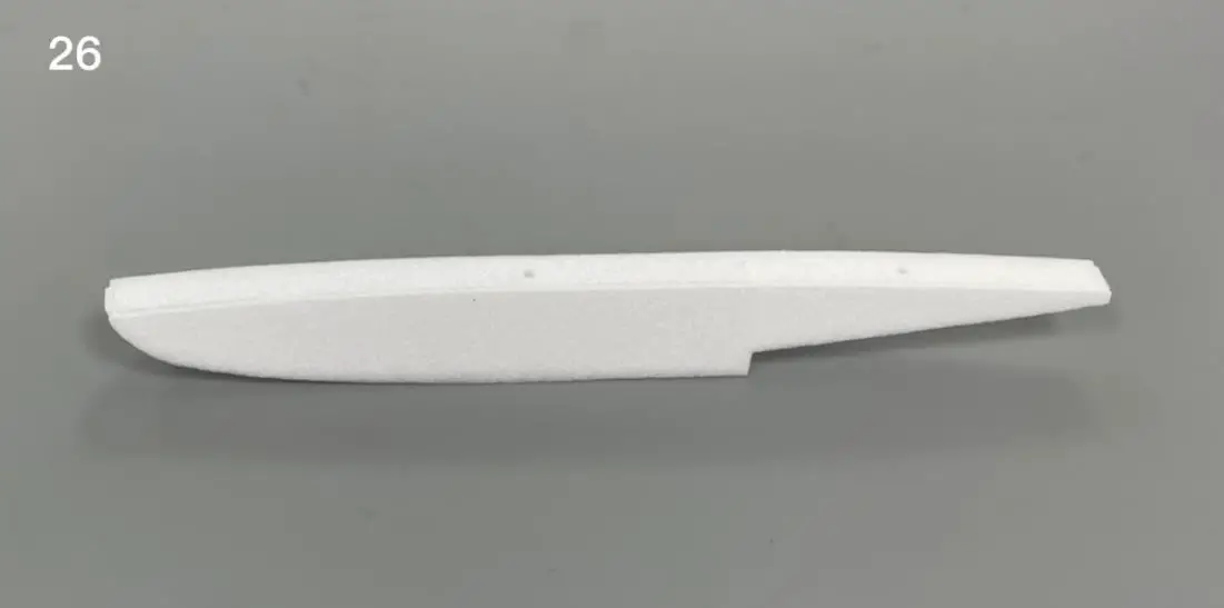
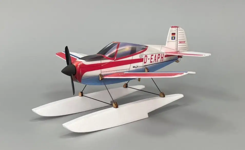
- Install the floats
Assembly complete!
Maiden flight
- The center of gravity of the aircraft is located at 5mm in front of the score line on the wing.
- The active range of ailerons, elevator and rudder is 5mm on both sides.
- Test glide on grass land before powered flight.
- Choose grass land with hand launch for maiden flight.


