![]()
User Manual
MD16U Human Body Temperature
Measurement Module![]()
Rev. 1.0
Zhejiang DALI Technology Co., Ltd.
MD16U thermal imaging module user manual
Product Introduction
The MD16U human body temperature measurement thermal imaging module is developed by DALI manufactured uncooled microbolometer detectors. MD16U outputs data with a resolution of 120×322 in UVC mode. The pseudo-color image and the temperature image are spliced up and down and output at the same time. The upper 120×160 is the pseudo-color image, the lower 120×160 is the temperature data, and the last 2 lines of information output other information.
The module supplies power through the USB interface, communicates control and data output in UVC mode, and is easy to integrate with other application systems.
MD16U module can be connected to a computer for independent application and is also suitable for integration with other human body temperature measurement and screening equipment: temperature measurement flat panel, temperature measurement gate, temperature measurement security gate, temperature measurement attendance machine, temperature measurement access control intercom and other equipment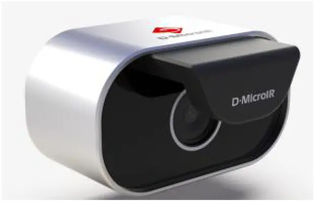
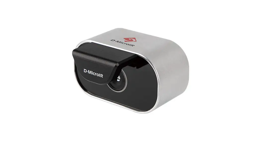
Picture .1:MD16T Module appearance
MD16U Features and Advantages:
- Integrated mini black body, high-temperature measurement accuracy, stable performance, and small influence of working environment temperature.
- Full-frame human body temperature measurement: Each frame of the image provides 160×120 temperature point data, suitable for various applications.
- UVC output to realize drive-free development
- Small size, convenient installation, universal single USB cable input, and output
- Flexible application: users can perform personalized algorithm processing such as back-end image stretching and pseudo-color rendering.
Precautions for module use::
- Use in strict accordance with the specified use conditions of the product, and the module needs to be used in an indoor no wind scene.
- When the system is used in integration, it is necessary to strengthen the heat dissipation and ensure uniform and stable temperature around the module and be isolated from other cold/heat sources to avoid severe fluctuations in ambient temperature.
- Take care to protect the surface of the lens to avoid scratches and oil stains from hard objects.
- The module should not look directly at high-temperature targets such as the sun to prevent high-temperature burns to the detector.
Technical Specifications
The detailed technical parameters of MD16U are described below:
Table 1:Technical Parameters
| Detector Type | Uncooled microbolometer array sensor |
| Resolution | 160×120 |
| Pixel Pitch | 17um |
| Pixel Pitch | 17um |
| NEED | ≤60mK (F/1,300K,60Hz) |
| Frame Rate | ≤12Hz(image and temp output at the same time) ≤14Hz(single image or temperature) |
| Image Calibration | Single point, two points, dead point replacement, etc., dynamic dead point correction, automatic gain, and false color (can be turned off) are completed before leaving the factory |
| Output Interface | UVC |
| Control Interface | UVC |
| Temperature Range | 30℃~40℃ |
| Temperature Accuracy | Inbuilt black body, ± 0.3°C (ambient temperature 20°C~30°C)/±0.5°C (ambient temperature 10°C~40°C) |
| Temperature Measurement Range | 0.5m |
| Distance Calibration | Support |
| Human Body Temperature Calibration | Support surface temperature / human body internal temperature |
| Temperature Data Output | 120×322(Image and temperature stitching up and down) 120×162(Gray value or temperature data) |
| Working voltage | DC 4.4V~5.5V |
| Power consumption | 0.8W(room temperature steady state), peak 2.5W |
| Working Temp | 10℃~40℃ |
| Storage Temp | -40℃~60℃ |
| Dimension | 70mm×40mm×53mm |
| Install port | 2 M2 threaded holes on the bottom, 1 1/4′-20UNC threaded hole, 4 M2 threaded holes on the back |
| Lens | Athermalized fixed focus infrared lens |
| Focus | f3.85mm/F1.0 |
| FOX | 29.7°×38.9° |
| PC Software | Provide Windows version PC software, can view images, temperature measurement, etc. |
| SDK | Provide SDK, including data receiving, sending, parsing, output mode switching, filtering algorithm switch, automatic gain switch, pseudo-color calling, and distance correction interface |
Mechanical Parameters
The dimensions of the module are shown in Picture 2(unit: mm)
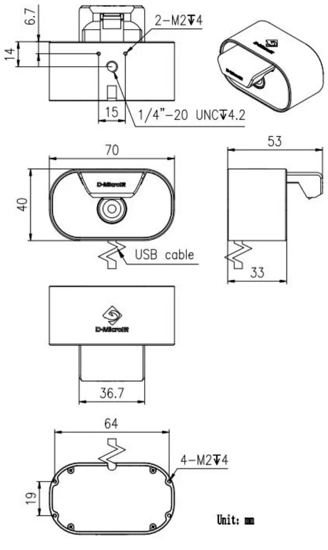 Picture 2:Module dimension
Electrical Parameters
The module output interface is a USB Type-A male data cable, which works in USB2.0 mode.
Power requirements input range 4.4V ~ 5.5V, currently greater than 500mA, more than 1A is recommended
Software protocol
The module is a UVC slave device with a VC interface and a VS interface inside.
The VC interface is used for module control, and the VS interface is used for image and temperature data output.
Use the “contrast” adjustment command in the VC interface to issue control commands, upload module response information, and control the basic composition and format of transmission data packets as shown in Table 3.
Table 3:Packet format
| No. | Definition | Bytes | Format |
| 1 | start byte | 1 | Fixed number:0x6e |
| 2 | status code | 1 | 0x00 |
| 3 | reserved bit | 1 | 0x00 |
| 4 | script | 1 | As shown in Table 4 |
| 5 | Data length (high order) | 1 | Indicates the length of number 9 data, see Table 4 “Data Length” column |
| 6 | Data length (low order) | 1 | |
| 7 | CRC1 (high order) | 1 | check code |
| 8 | CRC1 (low order) | 1 | |
| 9 | data | changeable | Actual data sent in little-endian mode, with variable length |
| 10 | CRC2 (high order) | 1 | check code |
| 11 | CRC2 (low order) | 1 |
CRC1 check: CCITT-16 checksum is used, CRC-CCITT ( 0xFFFF ), that is CRC-16/CCITT-FALSE
a) The check operation is performed on the four parts of “No. 1”-“No. 6”.
b) The check is formed at the backend and is checked at the module side. If the check fails, it needs to be retransmitted.
CRC2 check: CCITT-16 checksum is used, CRC-CCITT ( 0xFFFF ), that is CRC-16/CCITT-FALSE。
a) The check operation is performed on the six parts of “No. 1” – “No. 9”.
b) The check is formed at the backend and is checked at the module side. If the check fails, it needs to be retransmitted.
The table used for CRC1 and CRC2 checks is shown in Appendix 1
Table 4:Command
| Code | Dire action | Data | Length | Description |
| 0x04 | Serial down | 0x00:Turn on single-point calibration (manual calibration) Example:6e 00 00 04 00 01 1d 4a 00 00 00 | 1 | Manual single-point calibration |
| 0x2a | Serial down | Auto Gain and Pseudo Color On Example:6e 00 00 2a 00 02 b0 ee 02 00 66 62 Auto Gain and Pseudo Color Off Example:6e 00 00 2a 00 02 b0 ee 02 01 76 43 | 2 | Automatic gain and pseudo-color switch |
| Serial down | The module temperature measurement data enables the human body compensation mode Example:6e 00 00 2a 00 02 b0 ee 0c 00 45 6d The module temperature measurement data closes the human body compensation mode Example:6e 00 00 2a 00 02 b0 ee 0c 01 55 4C | 2 | On/off state, it will take effect after the next shutter release, and it will be automatically saved in the module | |
| 0x84 | Serial down | Parameter 1~2: The number of data packets of the upgrade file Example:6e 00 00 84 00 02 16 73 05 00 ff f5 | 2 | Notify the module to upgrade, and inform the number of data packages, Note 2 |
| Serial up | Parameter 1~2: Request the packet number of the next data packet, the packet number starts from 0 Example:6e 00 00 84 00 02 16 73 00 00 00 00 | 2 | The module responds with 0x00 | |
| Serial down | Parameters 1 to 4: file length (sent in little-endian mode) Parameters 5 to 6: CRC of the entire file (sent in little-endian mode) Parameter 7~18: The modification time of the file (year, month, day, hour, minute) Parameters 19~30: The version number of the file (included in the file name) Parameter 31~50: reserved parameter, default 00. Example:6e 00 00 84 00 32 20 20 04 e7 00 00 dc 35 32 30 32 31 30 38 32 34 31 32 31 39 5a 32 30 30 30 38 32 34 31 32 31 39 00 00 00 00 00 00 00 00 00 00 00 00 00 00 00 00 00 00 00 00 40 1f | 50 | Firmware file length, verification, file modification time, version number, and other information. | |
| Serial up | Parameter 1~2: Request the packet number of the next data packet, the packet number starts from 1 Example:6e 00 00 84 00 02 16 73 01 00 33 31 | 2 | The module responds to the packet number 0x01; the next step starts to send the data packet of the file. | |
| Serial down | Parameter 1~2: the package number of the current package, starting from 1 Parameter 3~4: effective data length Parameter 5~: Valid data | ≤12800 | data pack | |
| 0x88 | Serial down | switch to a grayscale image Example:6e 00 00 88 00 01 53 71 00 00 00 00 switch to temperature image Example:6e 00 00 88 00 01 53 71 01 10 21 00 | 1 | switch to grayscale image and temperature image |
| 0x8a | Serial down | 0x00:Module reset restart Example:6e 00 00 8a 00 01 3d 11 00 00 00 | 1 | Module restart |
| 0xa4 | Serial down | Parameter 1:02 Parameter:2~5:distance, Unit is centimeter, float type Example:6e 00 00 a4 00 05 e0 52 02 00 00 a0 41 01 18 | 5 | The example is 20.0cm, the float value is 41 a0 00 00,sent in little |
| endian mode |
Note 1: The command packet is transmitted by using the “contrast” adjustment command of UVC. Only 2 bytes must be transmitted at a time. Therefore, when the length of the command packet (number of bytes) is not an even number, it needs to be filled with zeros at the end. Special attention should be paid to the high and low bits of the sending command. For example, the length (number of bytes) of the first 6e 00 00 04 00 01 1d 4a 00 00 00 is odd, and 0 should be added to 6e 00 00 04 00 01 1d 4a 00 00 00 00 , the module needs to receive the information in this order. If it is sent from a computer, the computer transmits the problem of size end and the content that needs to be sent on the computer is as follows
0x6e 0x00;
0x00 0x04;
0x00 0x01;
0x1d 0x4a;
0x00 0x00;
0x00 0x00;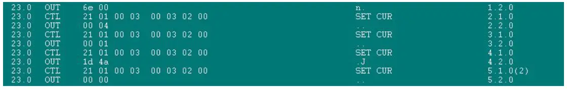
Note 2; Firmware Upgrade Instructions
The firmware data is sent to upgrade through UVC instruction, and 0x84 is used.
The process is:
A. Send the 0x84 downlink command for the first time, notify the module to enter the firmware upgrade state, and inform the firmware of the number of data packets (Byte), the module responds to the 0x84 command and returns 0x00, indicating that it is ready;
B. Send the 0x84 downlink command for the second time to notify the module of the total length, check the code, modification time, and version number of the firmware file to be upgraded. The module responds with 0x01, indicating that the packet number of the first data packet is requested, starting from 1;
C. Next, divide the firmware size into multiple packages by 12796Byte each time, each package is accompanied by the package number and length of the current package, and send all firmware data in turn through the 0x84 command. Note that CRC2 needs to be calculated correctly, and the modulo Each time the group receives a 0x84 firmware data packet, it will return a 0x84 response command to notify the upper computer that the reception is completed and request the packet number of the next data packet. If there is no 0x84 response, the current packet needs to be resent.
The last data packet may be less than 12800Byte in length, and it is sent according to the actual data length.
UVC Output
The module is a UVC slave device, and the VS interface is used for data transmission. When outputting data, the format is YUYV, and the size of each pixel is 2Byte.
The default state of the module is to output a pseudo-color image and temperature image at the same time, and the output resolution is 120×322. Lines 1 to 160 are pseudo-color images, lines 161 to 320 are temperature data, and the last two lines are status information.
The module can also be switched to output only pseudo-color image data, or only output temperature data, the output resolution is 120×162, the first row to the 160th row is pseudo-color image data or temperature data, and the last two rows are status information.
When acquiring data, the data is first read in the YUYV method, the pseudo-color image data is directly converted to RGB output, and the temperature data is converted to grayscale. The conversion relationship between the temperature measurement value Tc (°C) of the detection target and the grayscale value Vc (grayscale) of the temperature data is Tc= Vc/10–273;
In the output data, the last two lines are used to display the status information, and the information of each part is shown in Table 5. For the information of the two lines of status bits, the starting position is at the position of 0 points of the last two lines, after outputting the data of the previous array, the next 12Byte is the detector type. That is, Table 5 is output in order from the 0-point position of the last two lines.
Table 5: Information Format
| Name | No(Byte) | Remark | |
| Module Info | Detector type | 12 | Example: DM1716A 1st byte ~ 12th byte on line 321 |
| Detector number | 12 | Example: P2235A 12th byte~24th byte | |
| Firmware version number | 12 | Example: C20210081556 25th byte~36th byte | |
| bootloader version | 12 | 37th byte~48th byte | |
| Module model | 12 | Example: MD16U 49th byte~60th byte | |
| reserved | 12 | 61st byte~72th byte | |
| Shutter grayscale | 2 | 91st byte~92th byte | |
| TOUT gray value | 2 | 93rd byte~94th byte | |
| Center point information | 12 | Row coordinate (UINT16) starts at byte 105 column coordinates (UINT16) temperature (float) Grayscale (UINT32) | |
| Highest point information | 12 | Row coordinate (UINT16) starts at byte 117 column coordinates (UINT16) | |
| temperature (float) Grayscale (UINT32) | ||
| Lowest point information | 12 | Row coordinate (UINT16) starts at byte 129 column coordinates (UINT16) temperature (float) Grayscale (UINT32) |
| any point information | 12 | Row coordinate (UINT16) starts at byte 141 column coordinates (UINT16) temperature (float) Grayscale (UINT32) |
Note 1: TOUT gray value, shutter gray value, center point information, highest point information, and lowest point information are all in little-endian mode.
Note 2: The conversion relationship between the internal temperature of the detector Ts (°C) and the module TOUT gray value Vs (gray) is:
Ts = 190.64 – 0.02164 × Vs
(The following page is Appendix 1)
Appendix 1:
CRC checklist
| Item | CRC value | Item | CRC value | Item | CRC value | Item | CRC value |
| 0x00 | 0x0000 | 0x40 | 0x48c4 | 0x80 | 0x9188 | 0xc0 | 0xd94c |
| 0x01 | 0x1021 | 0x41 | 0x58e5 | 0x81 | 0x81a9 | 0xc1 | 0xc96d |
| 0x02 | 0x2042 | 0x42 | 0x6886 | 0x82 | 0xb1ca | 0xc2 | 0xf90e |
| 0x03 | 0x3063 | 0x43 | 0x78a7 | 0x83 | 0xa1eb | 0xc3 | 0xe92f |
| 0x04 | 0x4084 | 0x44 | 0x0840 | 0x84 | 0xd10c | 0xc4 | 0x99c8 |
| 0x05 | 0x50a5 | 0x45 | 0x1861 | 0x85 | 0xc12d | 0xc5 | 0x89e9 |
| 0x06 | 0x60c6 | 0x46 | 0x2802 | 0x86 | 0xf14e | 0xc6 | 0xb98a |
| 0x07 | 0x70e7 | 0x47 | 0x3823 | 0x87 | 0xe16f | 0xc7 | 0xa9ab |
| 0x08 | 0x8108 | 0x48 | 0xc9cc | 0x88 | 0x1080 | 0xc8 | 0x5844 |
| 0x09 | 0x9129 | 0x49 | 0xd9ed | 0x89 | 0x00a1 | 0xc9 | 0x4865 |
| 0x0a | 0xa14a | 0x4a | 0xe98e | 0x8a | 0x30c2 | 0xca | 0x7806 |
| 0x0b | 0xb16b | 0x4b | 0xf9af | 0x8b | 0x20e3 | 0xcb | 0x6827 |
| 0x0c | 0xc18c | 0x4c | 0x8948 | 0x8c | 0x5004 | 0xcc | 0x18c0 |
| 0x0d | 0xd1ad | 0x4d | 0x9969 | 0x8d | 0x4025 | 0xcd | 0x08e1 |
| 0x0e | 0xe1ce | 0x4e | 0xa90a | 0x8e | 0x7046 | 0xce | 0x3882 |
| 0x0f | 0xf1ef | 0x4f | 0xb92b | 0x8f | 0x6067 | 0xcf | 0x28a3 |
| 0x10 | 0x1231 | 0x50 | 0x5af5 | 0x90 | 0x83b9 | 0xd0 | 0xcb7d |
| 0x11 | 0x0210 | 0x51 | 0x4ad4 | 0x91 | 0x9398 | 0xd1 | 0xdb5c |
| 0x12 | 0x3273 | 0x52 | 0x7ab7 | 0x92 | 0xa3fb | 0xd2 | 0xeb3f |
| 0x13 | 0x2252 | 0x53 | 0x6a96 | 0x93 | 0xb3da | 0xd3 | 0xfb1e |
| 0x14 | 0x52b5 | 0x54 | 0x1a71 | 0x94 | 0xc33d | 0xd4 | 0x8bf9 |
| 0x15 | 0x4294 | 0x55 | 0x0a50 | 0x95 | 0xd31c | 0xd5 | 0x9bd8 |
| 0x16 | 0x72f7 | 0x56 | 0x3a33 | 0x96 | 0xe37f | 0xd6 | 0xabbb |
| 0x17 | 0x62d6 | 0x57 | 0x2a12 | 0x97 | 0xf35e | 0xd7 | 0xbb9a |
| 0x18 | 0x9339 | 0x58 | 0xdbfd | 0x98 | 0x02b1 | 0xd8 | 0x4a75 |
| 0x19 | 0x8318 | 0x59 | 0xcbdc | 0x99 | 0x1290 | 0xd9 | 0x5a54 |
| 0x1a | 0xb37b | 0x5a | 0xfbbf | 0x9a | 0x22f3 | 0xda | 0x6a37 |
| 0x1b | 0xa35a | 0x5b | 0xeb9e | 0x9b | 0x32d2 | 0xdb | 0x7a16 |
| 0x1c | 0xd3bd | 0x5c | 0x9b79 | 0x9c | 0x4235 | 0xdc | 0x0af1 |
| 0x1d | 0xc39c | 0x5d | 0x8b58 | 0x9d | 0x5214 | 0xdd | 0x1ad0 |
| 0x1e | 0xf3ff | 0x5e | 0xbb3b | 0x9e | 0x6277 | 0xde | 0x2ab3 |
| 0x1f | 0xe3de | 0x5f | 0xab1a | 0x9f | 0x7256 | 0xdf | 0x3a92 |
| 0x20 | 0x2462 | 0x60 | 0x6ca6 | 0xa0 | 0xb5ea | 0xe0 | 0xfd2e |
| 0x21 | 0x3443 | 0x61 | 0x7c87 | 0xa1 | 0xa5cb | 0xe1 | 0xed0f |
| 0x22 | 0x0420 | 0x62 | 0x4ce4 | 0xa2 | 0x95a8 | 0xe2 | 0xdd6c |
| 0x23 | 0x1401 | 0x63 | 0x5cc5 | 0xa3 | 0x8589 | 0xe3 | 0xcd4d |
| 0x24 | 0x64e6 | 0x64 | 0x2c22 | 0xa4 | 0xf56e | 0xe4 | 0xbdaa |
| 0x25 | 0x74c7 | 0x65 | 0x3c03 | 0xa5 | 0xe54f | 0xe5 | 0xad8b |
| 0x26 | 0x44a4 | 0x66 | 0x0c60 | 0xa6 | 0xd52c | 0xe6 | 0x9de8 |
| 0x27 | 0x5485 | 0x67 | 0x1c41 | 0xa7 | 0xc50d | 0xe7 | 0x8dc9 |
| 0x28 | 0xa56a | 0x68 | 0xedae | 0xa8 | 0x34e2 | 0xe8 | 0x7c26 |
| 0x29 | 0xb54b | 0x69 | 0xfd8f | 0xa9 | 0x24c3 | 0xe9 | 0x6c07 |
| 0x2a | 0x8528 | 0x6a | 0xcdec | 0xaa | 0x14a0 | 0xea | 0x5c64 |
| 0x2b | 0x9509 | 0x6b | 0xddcd | 0xab | 0x0481 | 0xeb | 0x4c45 |
| 0x2c | 0xe5ee | 0x6c | 0xad2a | 0xac | 0x7466 | 0xec | 0x3ca2 |
| 0x2d | 0xf5cf | 0x6d | 0xbd0b | 0xad | 0x6447 | 0xed | 0x2c83 |
| 0x2e | 0xc5ac | 0x6e | 0x8d68 | 0xae | 0x5424 | 0xee | 0x1ce0 |
| 0x2f | 0xd58d | 0x6f | 0x9d49 | 0xaf | 0x4405 | 0xef | 0x0cc1 |
| 0x30 | 0x3653 | 0x70 | 0x7e97 | 0xb0 | 0xa7db | 0xf0 | 0xef1f |
| 0x31 | 0x2672 | 0x71 | 0x6eb6 | 0xb1 | 0xb7fa | 0xf1 | 0xff3e |
| 0x32 | 0x1611 | 0x72 | 0x5ed5 | 0xb2 | 0x8799 | 0xf2 | 0xcf5d |
| 0x33 | 0x0630 | 0x73 | 0x4ef4 | 0xb3 | 0x97b8 | 0xf3 | 0xdf7c |
| 0x34 | 0x76d7 | 0x74 | 0x3e13 | 0xb4 | 0xe75f | 0xf4 | 0xaf9b |
| 0x35 | 0x66f6 | 0x75 | 0x2e32 | 0xb5 | 0xf77e | 0xf5 | 0xbfba |
| 0x36 | 0x5695 | 0x76 | 0x1e51 | 0xb6 | 0xc71d | 0xf6 | 0x8fd9 |
| 0x37 | 0x46b4 | 0x77 | 0x0e70 | 0xb7 | 0xd73c | 0xf7 | 0x9ff8 |
| 0x38 | 0xb75b | 0x78 | 0xff9f | 0xb8 | 0x26d3 | 0xf8 | 0x6e17 |
| 0x39 | 0xa77a | 0x79 | 0xefbe | 0xb9 | 0x36f2 | 0xf9 | 0x7e36 |
| 0x3a | 0x9719 | 0x7a | 0xdfdd | 0xba | 0x0691 | 0xfa | 0x4e55 |
| 0x3b | 0x8738 | 0x7b | 0xcffc | 0xbb | 0x16b0 | 0xfb | 0x5e74 |
| 0x3c | 0xf7df | 0x7c | 0xbf1b | 0xbc | 0x6657 | 0xfc | 0x2e93 |
| 0x3d | 0xe7fe | 0x7d | 0xaf3a | 0xbd | 0x7676 | 0xfd | 0x3eb2 |
| 0x3e | 0xd79d | 0x7e | 0x9f59 | 0xbe | 0x4615 | 0xfe | 0x0ed1 |
| 0x3f | 0xc7bc | 0x7f | 0x8f78 | 0xbf | 0x5634 | 0xff | 0x1ef0 |
The initial value of CRC is 0xFFFF.
Note: CRC does not directly check the table in Appendix 1, but is calculated according to the algorithm. The table in Appendix 1 is the table called during the calculation process. This table is used in the CRC algorithm source code.
The CRC check algorithm of the module is CRC-CCITT (0xFFFF), namely CRC-16/CCITT-FALS.


