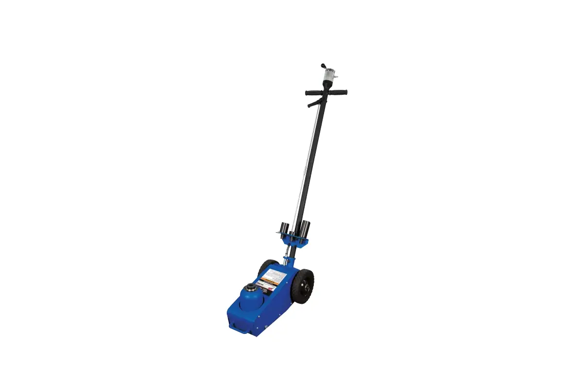
ATD-7328A 22-Ton Low Profile Axle Jack Owner’s Manual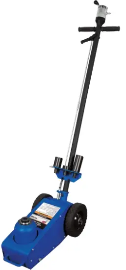
Features
- High speed air motor quickly raises the load to the desired height
- Air control knob allows precise lifting and lowering
- Welded pump for trouble free performance
- Heat-treated extension screw allows for maximum lift height
- Heavy-duty wheels with bearings for easy movement
- (3) adapters included: .8″, 2.4″, 3.9″
- (3) handle positions allow for easy storage, movement and access to lift point
- Meets or exceeds ASME/PASE 2014 standards
Specifications
- Capacity (Tons): 22
- Minimum Height: 9.06″
- Maximum Height with Adapter: 21.65″
- Extension Screw: 3.9″
- Handle Length: 48.4″
- Hydraulic Range: 4.72″
- Weight: 88.2 lbs.
Read this manual and follow all Safety Rules and Operating Instructions before using this product.
The safety alert symbol is used to alert you to potential personal injury hazards. Obey all ! safety messages that follow this symbol to avoid possible injury or property damage.
SAFETY AND GENERAL INFORMATION
Save these instructions. For your safety, read, understand, and follow the information provided with and on this device before using. The owner and/or operator should have an understanding of the device, its operating characteristics and safety operating instructions before operating the equipment. The owner and/or operator should be aware that use and repair of this product may require special skills and knowledge. Instructions and safety information should be read to and discussed with the operator in the operator’s native language, making sure that the operator comprehends their contents, before use of this equipment is authorized. If any doubt exists as to the safe and proper use of this device, remove from service immediately.
Inspect before each use. Do not use if abnormal conditions such as cracked welds, damaged, loose or missing parts are noted. Any equipment that appears damaged in any way, is found to be worn, or operates abnormally should be removed from service until repaired. If the equipment has been or is suspected to have been subjected to an abnormal load or shock, immediately discontinue use until inspected by a factory authorized repair facility (contact distributor or manufacturer for list of authorized repair facilities). It is recommended that an annual inspection be made by an authorized repair facility. Labels and Operator’s Manuals are available from the manufacturer.
PRODUCT DESCRIPTION
Hydraulic Axle Jacks are designed to lift, but not support, rated capacity partial vehicle loads consisting of one end of a vehicle. Immediately after lifting, support loads with a pair of appropriately rated jack stands.
PREPARATION
Reference replacement parts pages 6 and 7 for parts location and assembly sequence. Assemble, align and insert the handle assembly and handle position bar into the handle sleeve, then tighten the bolt on handle sleeve to prevent accidental removal of handle while in use.
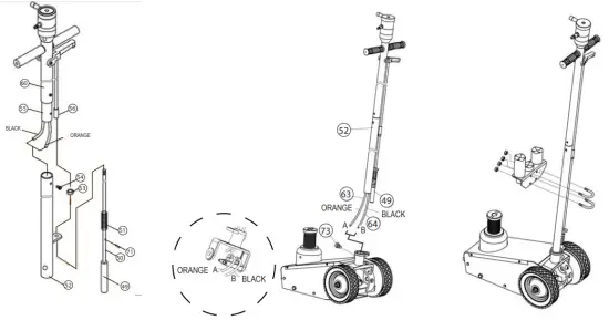
ASSEMBLY
- Install the handle assembly according to the assembly drawings below. Use bolt (#54) to lock handle-1 (#52) and handle-2 (#55); pass the slotted pin (#49) through the hole on handle-1 (#52) and screw the slotted pin (#49) with tie rod (#56), tighten the nut (#53) then put the R-pin (#71) through the hole in the slotted pin (#47), make sure that the R-pin is over the ear of handle-1.
- Use bolt (#73) to lock the handle and frame body; connect the PU tube with the joint by same color.
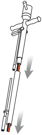
- Assemble the extensions to the handle according to the following drawings:
STEP 1
Route air hoses though the handle tubes as shown below:
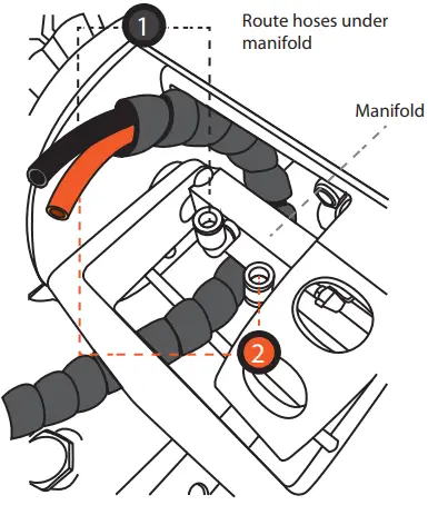
STEP 2
Note hose colors and numbers and make sure hoses are routed as shown below:
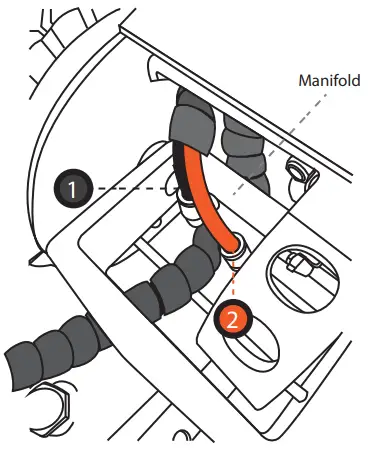
STEP 3
Connect hoses as shown below:
![]() Hose 1 should be inserted into Connector 1
Hose 1 should be inserted into Connector 1![]() Hose 2 should be inserted into Connector 2
Hose 2 should be inserted into Connector 2
Before Use
- Verify that the product and application are compatible, if in doubt call ATD Tools, Inc. Technical Service at 636-327-9050.
- Before using this product, read the operator’s manual completely and familiarize yourself thoroughly with the product, its components and recognize the hazards associated with its use.
- To familiarize yourself with basic operation, locate the air lever (#78) on the cross valve on top of the handle:
a. Rotate the air lever to the right, which is the “closed” position used to lift the load.
b. Rotate the air lever to the left, which is the “open” position used to lower the load.
c. Rotate the air lever to the middle, which is the “stop” position used to hold the load. - With ram fully lowered, remove the oil filler plug. Check oil level. Proper oil level should be just below the rim of the opening. Reinstall the oil filler plug.
- Pour a teaspoon of good quality air tool lubricant into the air supply inlet of the lift control valve. Connect to air supply, then squeeze the lift control valve for 3 seconds to evenly distribute lubricant.
NOTICE: These models are equipped with 1/4″ NPT air couplers. If installing a different air coupler, ensure thread tape or compound is used on connections. To ensure dependable, trouble free operation an inline air dryer and oiler is recommended. - Ensure that jack rolls freely. Raise and lower the unloaded ram throughout the lifting range before putting into service to ensure the jack operates smoothly. Replace worn or damaged parts and assemblies with ATD Tools, Inc. authorized replacement parts only.
Bleeding/Venting Trapped Air
- Open oil filler plug.
- Rotate the air lever to the right slightly to activate the air motor for slow pumping.
- Rotate the air lever to the left slightly to activate the air motor for slow pumping.
- Repeat steps 2 and 3 several times.
- Rotate air lever to the left until the ram is fully retracted.
- Check oil level and reinstall oil filler plug.
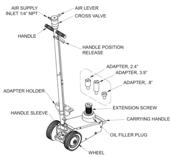
Figure 1
![]() WARNING
WARNING
- Study, understand, and follow all instructions before operating this device.
- Do not exceed rated capacity.
- Use only on hard, level surface.
- Lifting device only. Immediately after lifting, support the vehicle with appropriate means.
- Do not move or dolly the vehicle while on the jack.
- Lift only on areas of the vehicle as specified by the vehicle manufacturer.
- No alterations shall be made to this product.
- Failure to heed these markings may result in personal injury and/or property damage.
![]() WARNING
WARNING

To avoid crushing and related injuries:
- Never work on, under or around a load supported only by hydraulic jack.
- Always use adequately rated jack stands.
- Chock each unlifted tire in both directions.
- Do not use this device to lift, level, lower, support or move a house, mobile home, travel trailer, camper or any building structure.
- Be alert and sober when using this product. Do not operate under the influence of drugs or alcohol.
![]() The wheels provided with this jack are for positioning the jack under a load ONLY! The wheels are not load wheels. Do not try to dolly or move the vehicle with the jack!
The wheels provided with this jack are for positioning the jack under a load ONLY! The wheels are not load wheels. Do not try to dolly or move the vehicle with the jack!
OPERATION
Lifting
Note: The jack is equipped with handle position lock. To adjust the handle, release lock device by pulling the lever up, lever is spring loaded and will lock into desired position. Ensure lever locking mechanism is fully engaged before lifting.
- Connect adequate air source to the air supply inlet.
- Follow the vehicle manufacturer’s recommended guidelines for lifting. Engage the emergency brake and chock each unlined wheel in both directions to prevent inadvertent vehicle movement.
- Center jack saddle under lift point, then squeeze the lift control valve until saddle contacts the lift point. To lift, continue squeezing the lift control valve until load reaches desired height. Simply release your grip on the lift control valve to end lift event.
- Transfer the load immediately to appropriately rated jack stands.
WARNING: Only attachments and/or adapters supplied by the manufacturer should be used. Lift only on area of the vehicle as specified by the vehicle manufacturer.
WARNING: NEVER use hydraulic jack as a stand alone device! ALWAYS transfer the lifted load IMMEDIATELY to a pair of appropriately rated jack stands. Use one pair of jack stands per vehicle. Rated capacity is per pair only! Do not exceed rated capacity.
Lowering
WARNING: Be sure all tools and personnel are clear before lowering load.
- Raise load high enough to clear the jack stands.
- Remove jack stands carefully (always used in pairs).
- Rotate the cross valve air lever to the left to lower the load. Your ATD-7328A is equipped with a speed limiting valve so the lowering speed is controlled automatically.
- After removing jack from under the vehicle, fully retract the jack to reduce ram exposure to rust and contamination.
MAINTENANCE
Important: Use only good grade hydraulic jack oil. Avoid mixing different types of fluid and NEVER use brake fluid, turbine oil, transmission fluid, motor oil or glycerin. Improper fluid can cause premature failure of the jack and the potential for sudden and immediate loss of load. We recommend premium hydraulic oil or equivalent.
Adding/ Changing Oil
For best performance and longest life, replace the complete fluid supply at least once per year.
- With saddle fully lowered remove cover plate, then oil filler plug.
- Lay jack on its side and drain fluid into a suitable container.
NOTICE: Dispose of hydraulic fluid in accordance with local environmental regulations. - Set jack in its upright, level position.
- Fill with oil. Proper oil level is just below the rim of the opening. Reinstall the oil filler plug.
- Perform BleedingNenting Trapped Air procedure.
Lubrication
A periodic coating of light lubricating oil to pivot points, axles and hinges will help to prevent rust and assure that wheels move freely and the pump functions smoothly. To help ensure trouble free operation, an inline air dryer and oiler is recommended.
Cleaning
Periodically check the ram for signs of rust or corrosion. Clean as needed and wipe with an oily cloth. Note: Never use sandpaper or abrasive material on ram surfaces!
Storage
When not in use, store the jack with saddle fully lowered.
TROUBLESHOOTING
| Symptom | Possible Causes | Corrective Action |
| Jack will not lift |
|
|
| Jack will lift, but cannot maintain pressure |
|
|
| Jack will not lower after unloading |
|
|
| Poor lift performance |
|
|
| Will not lift to full extension | Low fluid level | Follow adding and changing oil procedure. |
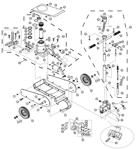
REPLACEMENT PARTS
Available Parts: Please refer to the Parts drawing when ordering parts. Not all components of this kit are replace-ment items, but are illustrated as a convenient reference of location and position in the assembly sequence. When ordering parts, give model number, serial number and description. Call your distributor for current pricing.
Model ATD-7328A
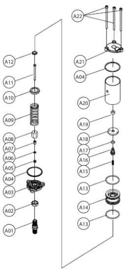
Air Motor Breakdown
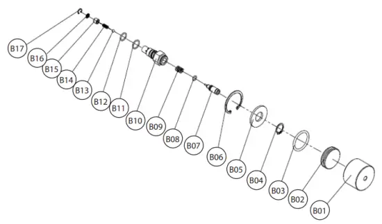
Release Valve Breakdown
| ITEM | ORDERING PART | PART DESCRIPTION | |
| 1 | BOLT | 10 | |
| 2 | – | BOLT | 2 |
| 3 | – | BOLT | 4 |
| 4 | – | NUT | 2 |
| 5 | – | FLAT WASHER | 2 |
| 6 | PRT7328A-06 | WHEEL | 2 |
| 7 | – | HANDLE POSMON SEAT ASSY | 1 |
| 8 | – | BASE PLATE | 1 |
| 9 | – | LEFT SIDE PLATE | 1 |
| 10 | – | RIGHT SIDE PLATE | 1 |
| 11 | – | HANDLE SOCKET | 1 |
| 12 | – | COVER PLATE | 1 |
| 13 | – | STEEL BALL | 1 |
| 14 | – | PUMP BODY WELDED COMPONENT | 1 |
| 15 | – | CONNECTING BLOCK | 1 |
| 16 | – | SCREW | 2 |
| 17 | PRT7328A-SK | COPPER WASHER | 2 |
| 18 | – | SPRING | 1 |
| 19 | – | BALL | 2 |
| 20 | – | SCREW | 4 |
| 21 | PRT7328A-SK | 0-RINIG | 4 |
| 22 | – | STEEL BALL | 1 |
| 23 | PRT7328A-SK | COPPER WASHER | 1 |
| 24 | – | STEEL BALL | 1 |
| 25 | – | BALL CUP | 1 |
| 26 | – | SPRING | 1 |
| 27 | – | SCREW | 1 |
| 28 | – | SCREW | 1 |
| 29 | – | RELEASE PLATE | 1 |
| 30 | PRT7328A-30 | RELEASE VALVE | 1 |
| 31 | PRT7328A-31 | AR PUMP | 1 |
| 32 | – | PISTON ROD | 1 |
| 33 | PRT7328A-SK | NYLON WASHER | 1 |
| 34 | PRT7328A-SK | 0-RING | 1 |
| 35 | PRT7328A-SK | WASHER | 1 |
| 36 | – | RINIG | 1 |
| 37 | PRT7328A-SK | 0-RING | 1 |
| 38 | PRT7328A-SK | 0-RING | 1 |
| 39 | PRT7328A-SK | U-RING | 1 |
| 40 | PRT7328A-SK | OIL PLUG | 1 |
| 41 | – | BLOCK | 2 |
| 42 | PRT7328A-42 | COUPLER | 2 |
| 43 | PRT7328A-43 | COUPLER | 1 |
| 44 | PRT7328A-44 | AR MOTOR SUPPLY HOSE (BLACK) | 1 |
| 45 | PRT7328A-45 | AIR MOTOR SUPPLY HOSE (BLACK) | 1 |
| 46 | PRT7328A-46 | AR MOTOR SUPPLY HOSE (ORANGE | 1 |
| 47 | PRT7328A-47 | COUPLER | 1 |
| 48 | PRT7328A-48 | COUPLER | 2 |
| 49 | – | SLOTTED PIN | 1 |
| 50 | – | TIE ROD | 1 |
| 51 | – | SPRING | 1 |
| 52 | – | HANDLE | 1 |
| 53 | – | NUT | 7 |
| 54 | – | SCREW | 2 |
| 55 | – | HANDLE CONNECTOR | 1 |
| 56 | – | TIE ROD | 1 |
| 57 | – | PINI | 1 |
| 58 | – | HANDLE LOCK | 1 |
| 59 | – | SCREW | 2 |
| 60 | – | HANDLE 1 | 1 |
| 61 | – | SCREW | 2 |
| 62 | – | HANDLE SLEEVE | 2 |
| 63 | PRT7328A-63 | AIR MOTOR SUPPLY HOSE (ORANGE) | 1 |
| 64 | PRT7328A-64 | AIR MOTOR SUPPLY HOSE (BLACK) | 1 |
| 65 | – | CROSS VALVE & AIR LEVER | 1 |
| 66 | – | ADAPTER – .8″ | 1 |
| 67 | – | ADAPTER – 2.4″ | 1 |
| 68 | – | ADAPTER – 3.9″ | 1 |
| 69 | – | R RV | 3 |
| 70 | – | U BOLT | 2 |
| 71 | – | R RV | 1 |
| 72 | – | BRACKET ASSEMBLY | 1 |
| 73 | – | SCREW | 1 |
| 74 | – | STEEL BALL BLOCK SLICE | 1 |
| 75 | PRT7328A-SK | 0-RING | 1 |
| 76 | PRT7328A-76 | HANDLE ASSEMBLYCOMPLETE | 1 |
| 77 | – | BRACKET ASSEMBLYAND HARDWARE | 1 |
| 78 | – | AIR LEVER | 1 |
| 79 | – | COUPLER | 1 |
| 80 | PRT7328A-SK | WASHER | 1 |
| 81 | – | CONNECTOR SEAT | 1 |
| 82 | – | COUPLER | 1 |
| 83 | – | CONNECTING BLOCK ASSEMBLY | 1 |
| 84 | PRT7328A-SK | DUST PREVENTION RING | 1 |
| 85 | – | PROTECTIVE SLEEVE | 1 |
| 86 | PRT7328A-86 | HYDRAULIC UNIT W/AIR MOTOR | 1 |
| ITEM | ORDERING PART | PART DESCRIPTION | |
| A01 | PUMP CORE SEAT | ||
| A02 | ROUND NUT | ||
| A03 | CYLINDER SEAT | 1 | |
| A04 | PRT7328A-SK | NYLON RING | |
| A05 | PRT7328A-SK | U-RING | |
| A06 | PRT7328A-SK | NYLON RING | 1 |
| A07 | PRT7328A-SK | COPPER RING | |
| A08 | ROUND NUT II | 1 | |
| A09 | SPRING | 1 | |
| A10 | CAP | ||
| Al 1 | AIR PUMP CORE | 1 |
| Al2 | – | CAP | 1 |
| A13 | PRT7328A-SK | 0-RING | 2 |
| A14 | – | PISTON | 1 |
| A15 | – | SPRING | 1 |
| A16 | – | PISTON | 1 |
| A17 | PRT7328A-SK | 0-RING | 1 |
| A18 | – | PISTON CAP | 1 |
| A19 | PRT7328A-SK | SEAL RING | 1 |
| A20 | – | CYLINDER | 1 |
| A21 | – | CYLINDER CAP | 1 |
| A22 | – | SCREW | 3 |
| B01 | – | RELEASE CYLINDER | 1 |
| B02 | – | RAM | 1 |
| B03 | PRT7328A-SK | 0-RING | 1 |
| B04 | – | CIRCLIP | 1 |
| B05 | – | WASHER | 1 |
| B06 | – | CIRCLIP | 1 |
| B07 | – | RELEASE VALVE ROD/PIN | 1 |
| B08 | PRT7328A-SK | 0-RING | 1 |
| B09 | – | SPRING | 1 |
| B10 | – | SEAT | 1 |
| B11 | PRT7328A-SK | 0-RING | 1 |
| B12 | PRT7328A-SK | 0-RING | 1 |
| B13 | – | STEEL BALL | 1 |
| B14 | – | SPRING | 1 |
| B15 | – | VALVE CORE | 1 |
| B16 | – | FILTER | |
| B17 | – | CIRCLIP | 1 |
WARRANTY
1 YEAR LIMITED WARRANTY
THIS WARRANTY AND CONFIRMED RECEIPT(S) SHOULD BE RETAINED BY THE CUSTOMER AT ALL TIMES
PURCHASED FROM:
DATE PURCHASED:
INVOICE/RECEIPT NUMBER:
Your ATD-7328A is warranted for a period of 12 months from the original purchase date.
For a period of one (1) year from your purchase date, ATD Tools Inc. will repair or replace (at its option) without charge, your ATD product if it was purchased new and the product has failed due to a defect in material or workmanship which you experienced during normal use of the product. This limited warranty is your exclusive remedy.
To access the benefits of this warranty, contact your supplier, or point of sale directly. You may be advised to return the product under warranty, freight prepaid, to your supplier for warranty determination.
If this ATD product is altered, abused, misused, modified, or undergoes service by an unauthorized technician, your warranty will be void. We are not responsible for damage to ornamental designs you place on this ATD product and such ornamentation should not cover any warnings or instructions or they may void the warranty. This warranty does not cover scratches, superficial dents, and other abrasions to the paint finish that occur under normal use. It also does not cover normal wear items such as but not limited to brushes, batteries, drill bits, drill chucks, pads or blades.
Subject to the law in your state:
(1) Your sole and exclusive remedy is repair or replacement of the defective product as described above. (2) ATD is not liable for any incidental damages, including but not limited to, lost profits and unforeseeable consequences. (3) The repair and replacement of this product under the express limited warranty described above is your exclusive remedy and is provided in lieu of all other warranties, express or implied. All other warranties, including implied warranties and warranties of merchantability or fitness for a particular purpose are disclaimed and, if disclaimer is prohibited, these warranties are limited to one year from your date of purchase of this product.
Some states’ laws do not allow limited durations on certain implied warranties and some states’ laws do not allow limitations on incidental or consequential damages. You should consult the law in your state to determine how your rights may vary.


