
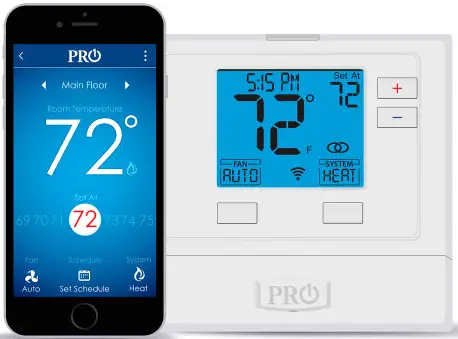
GLOBAL INDUSTRIAL T721i Thermostat Non Programmable
Pro1 Technologies
P.O. Box 3377
Springfield, MO 65808-3377
Toll Free : 888-776-1427
Web: www.pro1iaq.com
Hours of Operation: M-F 9AM – 6PM EST
Thermostat Application Guide
| Description | |
| Gas or Oil Heat | Yes |
| Electric Furnace | Yes |
| Heat Pump (No Aux. or Emergency Heat) | Yes |
| Heat Pump (With Aux. or Emergency Heat) | Yes |
| Multi-Stage Systems | Yes |
| Heat Only Systems | Yes |
| Cool Only Systems | Yes |
| Millivolt | No |
Power Type
Hardwire (24V Common Wire)
A trained, experienced technician must install this product.
Carefully read these instructions. You could damage this product or cause a
hazardous condition if you fail to follow these instructions.
Una version en espanol de este manual se puede descargar en la pagina web de la compania.
WIFI
- Frequency Range…………2.4 Ghz ISM radio band
- WIFI Module………………………….Supporting 802.11 B/G/N Standards
Installation Tips
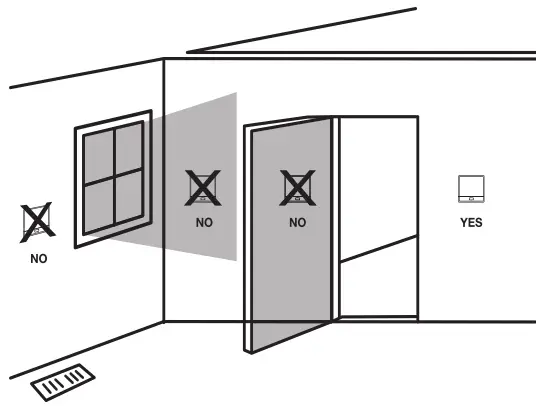
Wall Installation
The thermostat should be installed approximately 4 to 5 feet above the floor. Select an area with average temperature and good air circulation. Pick an installation location that is easy for the user to access. The temperature of the location should be representative of the building.
Do not install thermostat in locations:
- Close to hot or cold air ducts
- That are in direct sunlight
- With an outside wall behind the thermostat
- In areas that do not require conditioning
- Where there are dead spots or drafts (in corners or behind doors)
- Where there might be concealed chimneys or pipes

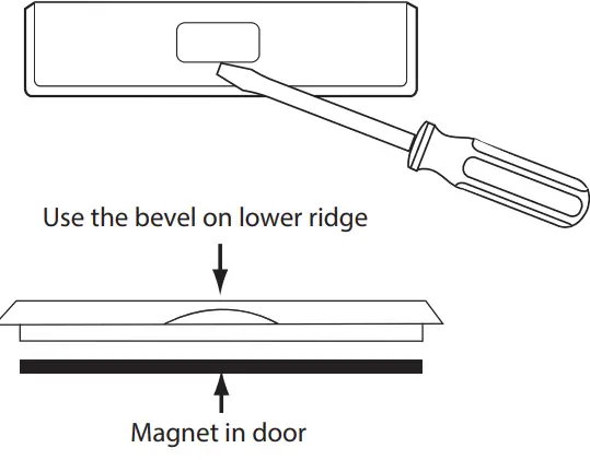
Removing The Private Label Badge
Gently slide a screwdriver into the bottom edge of the badge. Gently turn the screwdriver counter clockwise. The badge is held on by a magnet in the well of the battery door. The badge should pry off easily. DO NOT USE FORCE.
All of our thermostats use the same universal magnetic badge. Visit the company website to learn more about our free private label program.
Thermostat Quick Reference
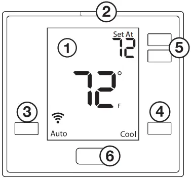
- LCD Display
- Glow in the dark light button
- Fan Button
- System Button
- Temperature Setpoint Buttons
- Private Label Badge
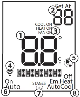
- Indicates the current room temperature
- Setpoint: Displays the selected setpoint temperature.
- System Operation Indicators: The COOL ON, HEAT ON or FAN ON will display when the COOL, HEAT, or FAN is on. The compressor delay feature is active if these are flashing.
- WIFI Indicator: Shown when connected to WiFi.
- Globe: Globe is displayed if an energy efficient temperature has been selected.
- Fan: Indicates the current fan setting.
- Stages: +1 will appear in the display when the first stage of heat or cool is on. +2 will appear for the second stage of heat.
- System: Indicates current system mode setting.
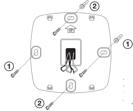
Subbase Installation
- Horizontal Mount
For horizontal mount put one screw on the left and one screw on the right. - Vertical Mount
For vertical mount put one screw on the top and one screw on the bottom. Electrical Hazard
Failure to disconnect the power before beginning to install this product can cause electrical shock or equipment damage.NOTE: To ensure a solid fit between the thermostat and subbase:
- Mount subbase on a flat wall.
- Use provided screws.
- Ensure drywall anchors are flush with wall.
- Push wires into wall
Mercury Notice
All of our products are mercury free. However, if the product you are replacing contains mercury, dispose of it properly. Your local waste management authority can give you instructions on recycling and proper disposal.
 Electrical Hazard
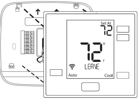
Mount Thermostat
Align the 4 tabs on the subbase with corresponding slots on the back of the thermostat, then push gently until the thermostat snaps in place.
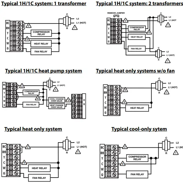
Wiring
- Power Supply
- Factory-installed jumper, remove only when installing on 2-transformer system.
- Use either O or B terminals for changeover valve.
- A 24 VAC 500mA common connection is required with this thermostat.

Replacement Thermostat Wiring
- If you are replacing a thermostat, make note of the terminal connections on the thermostat that is being replaced. In some cases the wiring connections will not be color coded. For example, the green wire may not be connected to the G terminal.
- Loosen the terminal block screws. Insert wires then retighten terminal block screws.
- Place nonflammable insulation into wall opening to prevent drafts.
- This thermostat requires a 24V common wire to the C terminal.
Caution: Electrical Hazard
Failure to disconnect the power before beginning to install this product can cause electrical shock or equipment damage.
Warning:
All components of the control system and the thermostat installation must conform to Class II circuits per the NEC Code.
Installation Tip Max Torque = 6in-lbs.
Do not overtighten terminal block screws, as this can damage the terminal block. A damaged terminal block can keep the thermostat from fitting on the subbase correctly or cause system operation issues.
Wiring Chart
For all systems, the following terminals are wired according to whether you have a single or dual transformer system as shown:
| RH RC | C | G | ||
| SINGLE TRANSFORMER SYSTEM | 24 VAC HOT JUMPER SHOULD REMAIN INSTALLED | 24 VAC Common 500mA | Blower / Fan | |
| DUAL TRANSFORMER SYSTEM | 24 VAC-Heat *REMOVE PROVIDED JUMPER | 24 VAC-Cool *REMOVE PROVIDED JUMPER | 24 VAC Common 500mA *FROM COOL TRANSFORMER | Blower / Fan |
*FAILURE TO REMOVE PROVIDED JUMPER ON DUAL TRANSFORMER INSTALLATIONS COULD CAUSE SEVERE DAMAGE TO HVAC SYSTEM
| O Terminal | Heat pump changeover valve– Energized during cooling |
| B Terminal | Heat pump changeover valve– Energized during heating |
Note: Devices such as a float switch that mechanically break circuits should be installed so that they break the control wire (Y) not the power (R). Interrupting the power circuit will shut off power to the thermostat completely and not allow it to operate.
If using in Heat Pump without Auxiliary or Emergency heat application, please see wiring diagram on previous page.
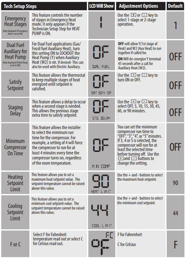
To enter tech setup
- Press and hold the + and – buttons for 3 seconds.
- Press and hold the TECH button for 3 seconds.
- Configure the installer options as desired using the table below. Use the + or – buttons to change settings and the lower left and right buttons to move from one step to another.
- To exit tech setup: press and hold the + and – buttons for 3 seconds, or wait 60 seconds.
Tech Setup Steps LCD Will Show Adjustment Options Default Room Temperature Calibration This feature allows the installer to change the calibration of the room temperature display. For example, if the thermostat reads 70 degrees and you would like it to read 72 then select +2. 0 CALIBRATE
You can adjust the room temperature display to read 4˚above or below the factory calibrated reading. O Compressor Short Cycle Delay The compressor short cycle delay protects the compressor from “short cycling”. This feature will not allow the compressor to be turned on for 5 minutes after it was last turned off. 0N COMP DELAY
Selecting “ON” will not allow the compressor to be turned on for 5 minutes after the last time the compressor was switched off. Select “OFF” to remove this delay. ON Cooling Swing
The swing setting often called “cycle rate”, “differential”, or “anticipation” is adjustable. A smaller swing setting will cause more frequent cycles and a larger swing setting will cause fewer cycles. COOL SWING
The cooling swing setting is adjustable from 0.2˚ to 2˚. A swing setting of 0.5˚will begin cooling at approximately 0.5˚ above the setpoint and stop approximately 0.5˚ below the setpoint. 0.5 ˚F
Heating Swing
The swing setting often called “cycle rate”, “differential”, or “anticipation” is adjustable. A smaller swing setting will cause more frequent cycles and a larger swing setting will cause fewer cycles. HEAT SWING
The heating swing setting is adjustable from 0.2˚ to 2˚. A swing setting of 0.5˚will begin heating at approximately 0.5˚ below the setpoint and begin approximately 0.5˚ above the setpoint. 0.5 ˚F
Heat Pump
When set to ON this thermostat will operate a heat pump system (default). If set to OFF this thermostat will operate a conventional system, and the next tech step will not appear. HEAT PUMP
ON – Configured to operate heat pump system. OFF – Configured to operate conventional system
See page 5 for terminal designations.
ON System Set
You can configure the system switch for the particular application. Heat – Off – Cool, Heat – Off, Cool – Off, Heat – Off – Cool – Auto.Note: Emergency Heat is available in heat pump mode only. SYSTEM SET Off Em.Heat AutoCool
Use the + or – buttons until the desired application is flashing. AUTO = (Auto Changeover) Heat Off Cool 
Tech Setup Steps LCD Will Show Adjustment Options Default 12 or 24 Hour Clock You can select either a 12 or 24 hour clock setting. 12 CLOCK SET
Use the + or – key to select 12 or 24 hour clock. 12 Display Light The display light can be configured to operate 3 different ways. To come on only when the Light Key is pressed, when Any Key is pressed, or stay on ALL of the time. OF DISP LIGHT
AUTO “AU” – Any key ON ON – light always on
OFF – light on when any button is pressed
OFF Programmable
You can configure this thermostat to accept a programmed schedule from the mobile App. ON Select “OF” to configure the thermostat for NON-Program- mable. (Time of day will NOT appear on display). Select “ON” to configure the thermostat for programmable operation, from the app.
ON
Fan Operation
Select GAS for systems that control the fan during a call for heat. Select ELEC to have the thermostat control the fan during a call for heat. EL – Electric for thermostat control GS- Gas for system control
EL
WIFI Setup
Operation of the FAN & SYSTEM button when connected to WIFI and running a programmable schedule from the app:
- When the set at temperature is changed while an app schedule is running, the thermostat will enter a temporary hold, and the Fan and System buttons change to RUN and HOLD for 15 seconds. If you wish to enter PERMANENT HOLD press the HOLD button at this time.
- If you don’t press the HOLD button when the HOLD icon appears the thermostat will remain in temporary hold for 4 hours.
- When connected to WIFI you may also have the ability to turn programming ON or OFF by pressing and holding the FAN button for 3 seconds.
These WIFI Technician steps/ options are intended for information and trouble-shooting. They are not used for installation or initial setup.
Follow these steps to enter the WIFI-technical information menu.
- Press and hold the + and – buttons together for 3 seconds.
- Press the WIFI button on the lower left.
- The bottom of the display will show:
“WIFI IDLE” if NOT connected to WIFI and the connected WIFI SSID when it is connected. - If the bottom right button is pressed, the bottom of the display will show the WIFI firmware version that is installed on the thermostat. If the bottom right button is pressed again, the bottom of the display will show the SSID # of the thermostat. If the bottom right button is pressed again, you will return to step 3.
The only normal function you would use this step for would be to RESET WIFI provisioning. For example: If you replaced your home WIFI router and need to connect via a different network.
Follow these steps to enter the WIFI-technical information menu.
- Go through steps 1 and 2 from the WIFI menu on the left.
- Press the bottom right button until you get to the WIFI reset screen.
- On the WIFI reset window, press and hold the plus button for 3 seconds.
- After 3 seconds, the thermostat will return to the home screen and “WIFI RESET” will appear in the text field.
- To confirm that the WIFI is reset the chainlink and broadcast icons will disappear.
Note: This step is used to start the commissioning process.
- This step allows an alternative way to enable the thermostat network.
- Using the WIFI pairing approach is optional if the installer didn’t use the light button to start the commissioning process.
- When this step is taken, the installer can open the app and continue the commissioning process.
WIFI Pairing Screen
- Press and hold the + and – buttons together for 3 seconds.
- Press the WIFI button on the lower left corner of the display.
- Press the bottom right button until you see the “WIFI PAIR” screen.
- On the “WIFI PAIR” screen, press and hold the plus button for 3 seconds.
- Afterwards, the thermostat will return to the home screen and the thermostat network ID will appear in the text field of the screen. (Example: TSTAT-XXXX)
Specifications
- The display range of temperature … 41˚F to 95˚F (5˚C to 35˚C)
- The control range of temperature…. 44˚F to 90˚F (7˚C to 32˚C)
- Load Rating……………………………………….. 1 amp per terminal, 1.5 amp maximum all terminals combined
- Swing (cycle rate or differential) …… Heating is adjustable from 0.2˚ to 2.0˚ Cooling is adjustable from 0.2˚ to 2.0˚
- Power source …………………………………….18 to 30 VAC, NEC Class II, 50/60 Hz for hardwire Battery power from 2 AA Alkaline batteries
- Operating ambient …………………………. 32˚F to +105˚F (0˚C to +41˚C)
- Operating humidity ………………………… 90% non-condensing maximum
- Dimensions of thermostat …………….. 4.7” W x 4.3” H x 0.9” D
WIFI
- Frequency Range…………2.4 Ghz ISM radio band
- WIFI Module………………………….Supporting 802.11 B/G/N Standards


