![]() ANBAUANLEITUNG
ANBAUANLEITUNG
mounting instructions
FRS.06.112.10200
contiene
FRS.06.112.80200/S
FRS.00.112.10000
MOUNTING INSTRUCTIONS
Revision: 01 Datum / Date: 07 – 2020
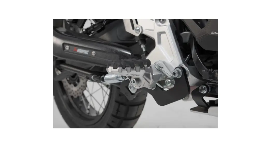
Mounting kit for EVO footrest
Thank you for choosing this premium product from SW-MOTECH. Please visit our webshop for additional information, such as application charts and PDF mounting instructions. Any other documents that may be required (e.g. ABE certifications), are also available for download at our webshop. Installation and/or maintenance of this product require good technical understanding! For your own safety, SW-MOTECH recommends having installation and/or servicing carried out by a specialist workshop! SW-MOTECH assumes no liability for damage caused by improper installation and/or maintenance work! Carefully follow all the directions given in the mounting instructions and pay attention to all relevant information in the vehicle manual during assembly. Nonconformance can lead to vehicle damage or even endanger the driver! These mounting instructions are written based on our current state of knowledge. Legal requirements for accuracy do not exist. This product was developed for vehicles in their factory setting. Compatibility with original accessory parts or other manufacturers’ accessory parts is not guaranteed. Furthermore, BEFORE installing this product, make sure that all moving parts (e.g. the chain) are in the original state of maintenance. Installed accessories can change the driving behavior and/or stability of your vehicle.
GENERAL INFORMATION
Observe the country-specific regulations concerning vehicle registration/ operation as well as TUV regulations if applicable. If required, register installed parts in the vehicle documents through an appropriate inspection authority.
PREPARATION: Read the mounting instructions carefully and make sure that all items of the parts list are included. Make sure that your vehicle is parked safely and cannot fall over. Turn off the engine and remove the ignition key. Let the motor/exhaust cool off if necessary. Disconnect the vehicle battery when working on the electrical system. Use appropriate tools. Have another person to help you.
MOUNTING: All parts and connections removed from the vehicle must be reinstalled in accordance with the vehicle manufacturer’s specifications or replaced by parts delivered by SW-MOTECH. Secure all threads, unless otherwise specified, with a medium-strength liquid thread locker. Torque specifications undefined by SW-MOTECH must be obtained from the vehicle manufacturer or by a specialist workshop!
FUNCTION CHECK: After installation makes sure that all parts and connections previously removed are properly replaced. Also, make sure that no moving parts are obstructed and no function of the vehicle is hindered in any way. Cables and hoses must not rub and/or be pinched. Before starting to ride, perform a comprehensive check of all functions. After the first 50 km and then at regular intervals, check the tightening torque of all screw connections and the proper fit of the product.
PRODUCT SPECIFIC INFORMATION
ATTENTION: round clearance can be reduced by this product! Special care should be taken when cornering at extreme lean angles!
Packed by:
Date of packaging:
SLU-MOTECH®
SW-MOTECH GmbH & Co. KG
| Ernteweg 7-10 35282 Rauschenberg Germany | Tel. / phone + 49 (0)6425 / 8168 – 050 Fax / fax + 49 (0)6425 / 8168 – 10 www.sw-motech.com |
| step | No. | Item No. / Description a | Part | Quantity b | N.mc |
| FRS.06.112.80200/S | Mounting kit for EVO footrest | ||||
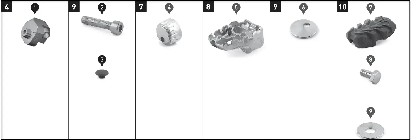
| 4 | (1) | FRS.56.112.Z15L / R | Hinge Adapter; left / right | 2 /2 | |
| 9 | (2) | M8 x 35; DIN 912; 10.9 | Hexagon Socket Screw | 2 /2 | 30 |
| (3) | KEK.00.M6.ISK | Plastic Cap | 2 /2 | ||
| FRS.00.112.10000 | EVO footrest [sold separately) | ||||
| 7 | (4) | FRS.00.112.002 | Positioning Cone | 2 /2 | |
| 8 | (5) | FRS.00.112.001 | Footrest | 2 /2 | |
| 9 | (6) | FRS.00.112.005 | Mounting Plate | 2 /2 | |
| 10 | (7) | FRS.00.112.900.01 | Rubber Pad | 2 /2 | |
| (8) | M5 x 12; DIN 933 | Hexagon Screw; stainless steel | 2 /2 | 3.5 | |
| (9) | d 5,3; DIN 9021 | Edelstahl Washer; stainless steel | 2 /2 |
8.8
| Regelgewinde / Coarse Thread 0 | P44 | M5 | 146 | 148 | M10 | M12 |
| Stahl FK 8.8 / Steel CL 8.8 In | 2,8 | 5,5 | 9,6 | 23 | 46 | 79 |
10.9
| Regelgewinde / Coarse Thread 0 | M4 | M5 | M6 | M8 | M10 | M12 |
| Stahl FK 10.9 / Steel CL 10.9 Wm | 4,1 | 8,1 | 14 | 34 | 67 | 115 |
Note: 8 All measurements in millimeters. b The second number indicates the total. quantity of the part in the delivery. c No torque specifications: Use the torque defined by the vehicle manufacturer! The standard torque in this table can be used as long as it is within the vehicle manufacturer’s specifications.
MOUNTING
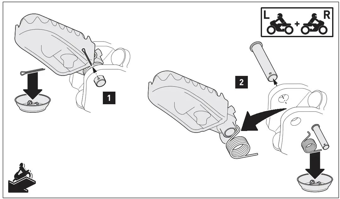
NOTE: The installation is shown on the left side of the vehicle only. Repeat the same procedure on the right side of the vehicle.
NOTE: Before removing the original footrest, make sure to note the order and direction of the original mounting parts.
Step [1]: Remove the original pins on both sides.
Step [2]: Remove the original footrests.
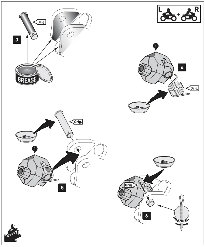
Step [3]: Clean the footrest holders thoroughly. Apply some grease to the inside of the footrest holders and the original pins (Orig.).
Step [4] – [6]: Attach the hinge adapters (1) with the shown original parts (Orig.) to the footrest mounts.
ATTENTION: The beveled surface of the hinge adapters pi must be faced upwards!
Step [7]: Insert the positioning cones (4) onto the star-shaped cones of the hinge adapters (1). The height of the footrests (5) can be adjusted individually by the various mounting positions (see right detail drawing).
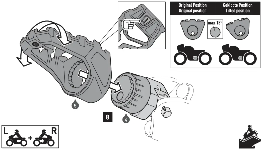
ATTENTION: Make sure to align the positioning cones (4) synchronously on each side! For orientation use the markings on the hinge adapters (1) and the positioning cones (41 (see left detail drawing.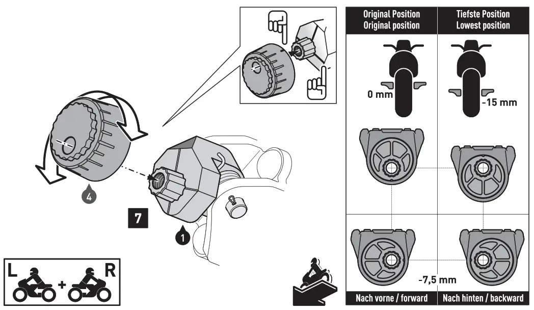 Step [8]: Insert the footrests (5) onto the positioning cones (4). The inclination angle of the footrests (5) can be adjusted individually by the toothing of the positioning cones (4) (not more than 18°; see right detail drawing).
ATTENTION: Make sure to align the footrests (5) synchronously on each side! For orientation use the markings on the positioning cones (4) (see left detail drawing).
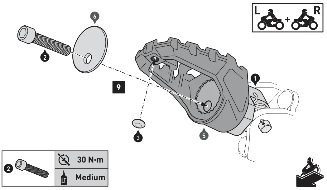
Step 9: Attach the footrests (5) LOOSELY to the hinge adapters as shown in the drawing. Check the synchronous alignment once again and the ergonomics. Then attach the footrests (51 to the hinge adapters (1).
ATTENTION: Use a medium-strength liquid thread locker! Tighten the screws as specified.
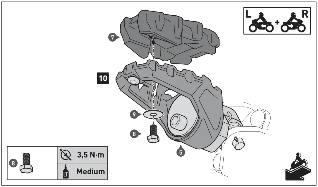
HINWEIS: Dieser Montageschritt ist optional.
This step is optional.
Step (10): Attach the rubber pads 14) to the footrests (51, as shown in the drawing.
ATTENTION: Use a medium-strength liquid thread locker! Tighten the screws as specified.
MOUNTING INSTRUCTIONS
Revision: 00 Datum / Date: 12 – 2016
EVO Footrests
Thank you for choosing this premium product from SW-MOTECH. Please visit our webshop for additional information, such as application charts and PDF mounting instructions. Any other documents that may be required (e.g. ABE certifications), are also available for download at our webshop. Installation and/or maintenance of this product require good technical understanding! For your own safety, SW-MOTECH recommends having installation and/or servicing carried out by a specialist workshop!
SW-MOTECH assumes no liability for damage caused by improper installation and/or maintenance work! Carefully follow all the directions given in the mounting instructions and pay attention to all relevant information in the vehicle manual during assembly. Nonconformance can lead to vehicle damage or even endanger the driver! These mounting instructions are written based on our current state of knowledge. Legal requirements for accuracy do not exist.
This product was developed for vehicles in their factory setting. Compatibility with original accessory parts or other manufacturers’ accessory parts is not guaranteed. Furthermore, BEFORE installing this product, make sure that all moving parts (e.g. the chain) are in the original state of maintenance. Installed accessories can change the driving behavior and/or stability of your vehicle.
GENERAL INFORMATION
Observe the country: specific regulations concerning vehicle registration/operation as well as TUV regulations if applicable. If required, register installed parts in the vehicle documents through an appropriate inspection authority.
PREPARATION: Read the mounting instructions carefully and make sure that all items of the parts list are included. Make sure that your vehicle is parked safely and cannot fall over. Turn off the engine and remove the ignition key. Let the motor/exhaust cool off if necessary. Disconnect the vehicle battery when working on the electrical system. Use appropriate tools. Have another person to help you.
MOUNTING: All parts and connections removed from the vehicle must be reinstalled in accordance with the vehicle manufacturer’s specifications or replaced by parts delivered by SW-MOTECH.
Secure all threads, unless otherwise specified, with a medium-strength liquid thread locker. Torque specifications undefined by SW-MOTECH must be obtained from the vehicle manufacturer or by a specialist workshop!
FUNCTION CHECK: After installation makes sure that all parts and connections previously removed are properly replaced. Also, make sure that no moving parts are obstructed and no function of the vehicle is hindered in any way. Cables and hoses must not rub and/or be pinched. Before starting to ride, perform a comprehensive check of all functions. After the first 50 km and then at regular intervals, check the tightening torque of all screw connections and the proper fit of the product.
PRODUCT SPECIFIC INFORMATION ATTENTION: Pay attention to the mounting instructions included with the EVO footrest kit!
Packed by:
Date of packaging:
SLU-MOTECH®
SW-MOTECH GmbH & Co. KG
| Ernteweg 7-10 35282 Rauschenberg Germany | Tel. / phone + 49 (0)6425 / 8168 – 050 Fax / fax + 49 (0)6425 / 8168 – 10 www.sw-motech.com |
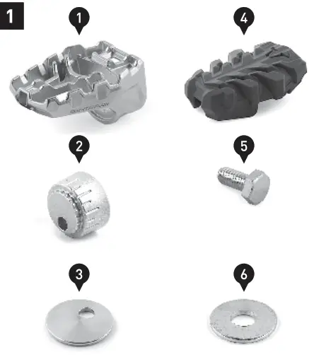
PARTS LIST
| Step | No. | Item No. / Description | Part | Quantity** | Nm*** |
| 1 | (1) | FRS.00.112.001 | EVO Footrest | 2/2 | |
| (2) | FRS.00.112.002 | Positioning Cone | 2/2 | ||
| (3) | FRS.00.112.005 | Mounting Plate | 2/2 | ||
| (4) | FRS.00.112.900.01 | Rubber Pad | 2/2 | ||
| (5) | M5 x 12; DIN 933 | Hexagon Screw; stainless steel | 2/2 | 3.5 | |
| (6) | d 5,3; DIN 9021 | Washer; stainless steel | 2/2 |
8.8
| Regelgewinde / Coarse Thread 0 | P44 | M5 | 146 | 148 | M10 | M12 |
| Stahl FK 8.8 / Steel CL 8.8 In | 2,8 | 5,5 | 9,6 | 23 | 46 | 79 |
10.9
| Regelgewinde / Coarse Thread 0 | M4 | M5 | M6 | M8 | M10 | M12 |
| Stahl FK 10.9 / Steel CL 10.9 Wm | 4,1 | 8,1 | 14 | 34 | 67 | 115 |
* All measurements in millimeters.
** The second number indicates the total quantity of the part in the delivery.
*** No torque specifications: Use the torque defined by the vehicle manufacturer! The standard torque in this table can be used as long as it is within the vehicle manufacturer’s specifications.
MOUNTING
ATTENTION: Pay attention to the mounting instructions included with the EVO footrest kit!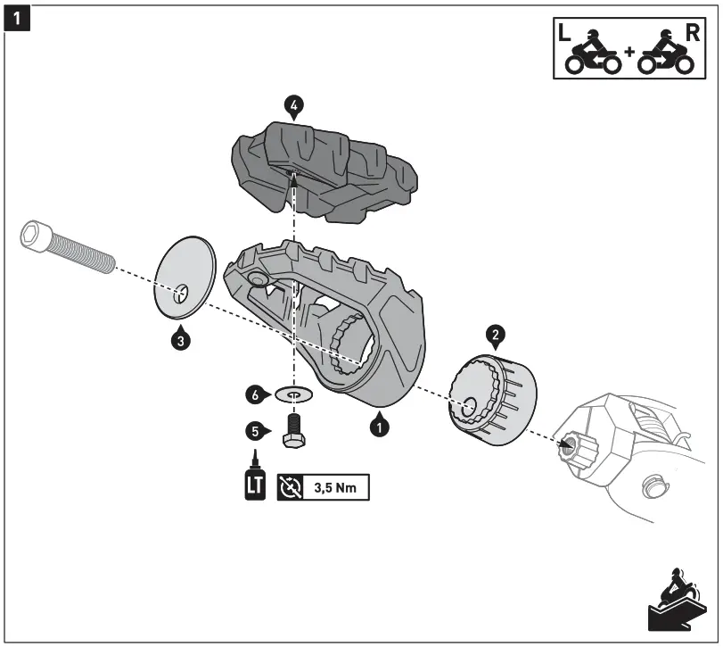
Copyright by
SW-MOTECH GmbH & Co. KG
Errors and omissions excepted. Technical and design modifications are subject to change.


 Instruction Manual")