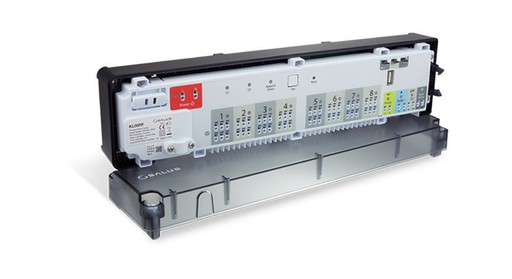
![]() ZigBee network wireless wiring centre (8 zones), 24 V AC
ZigBee network wireless wiring centre (8 zones), 24 V AC
Model: KL08RF 24V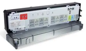
User manual
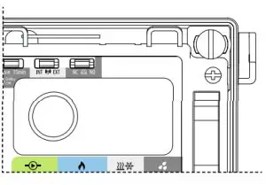
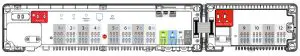
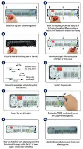
Wiring centre description
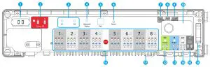
| 1. Cartridge fuse 5 x 20 mm 12 A 2. Power Supply 3. Thermostat grouping status 4. Network Status diode 5. Pair button 6. Reset button | 7. Delay jumper 8. INT/EXT antenna jumper 9. NC/NO actuators jumper 10. ZigBee network coordinator 11. Terminals for actuators 12. Pump control output | 13. Boiler control output 14. CO terminal 15. Dew point sensor input (humidistat) 16. Serial connector for the KL04RF 24V extension 17. External antenna connector |
 RX10RF (optional)
Additional, a wireless device control module that can be used
– for example – when we can’t use a cable between the KL08RF 24V wiring centre and the boiler.
Introduction
The KL08RF 24V wireless wiring centre is a part of the iT600RF system. In combination with the wireless thermostats from iT600RF series, KL08RF 24V provides comfortable and reliable heating control. It is equipped with the control outputs for the pump and boiler and has been designed to work with NC or NO actuators.
In Offline mode, communication with the wireless thermostats from iT600RF series must be done through the CO10RF co-ordinating unit, which is in the package together with the wiring centre. To work in Online mode (via the SALUS Smart Home app) KL08RF 24V must be connected to the Internet gateway UGE600. In one ZigBee network (Online or Offline) up to 9 KL08RF 24V wiring centres can be connected. KL08RF 24V increases the ZigBee network range.
Product compliance
This product complies with the essential requirements and other relevant provisions of Directives: EMC 2014/30/EU, LVD 2014/35/EU, RED 2014/53/EU and RoHS 2011/65/EU. The full text of the EU Declaration of Conformity is available at the following internet address: www.saluslegal.com.
 Safety information
Use in accordance with the regulations. Indoor use only. Keep your device completely dry. Disconnect your device before cleaning it with a dry cloth. This accessory must be fitted by a competent person, and installation must comply with the guidance, standards, and regulations applicable to the city, country, or state where the product is installed. Failure to comply with the relevant standards could lead to prosecution.
Technical information
| Power supply | 24V AC |
| Max load | 3 A |
| Inputs | (0 terminal Dew point sensor (humidistat) |
| Outputs | Pump control Boiler control Terminals for actuators |
| Radiofrequency | ZigBee 2,4 Glitz |
| Dimensions Immel | 355x83x67 |
- Fuse Note: Fuse replacement should be done when the wiring centre is disconnected from the power supply 24 V AC.
The main fuse is located under the housing cover, at the main terminals and protects the wiring centre and devices powered by it. Use cartridge fuse-type 5 x 20 mm – nominal burn rate 12 A. To remove the fuse, lift the socket with a flat screwdriver and pull out the fuse. - Power Supply

- Thermostat grouping status
This function is only available in Offline mode (together with CO10RF coordinator) – it means MASTER thermostats will affect SLAVE thermostats within a specific group, which is possible only when thermostats are paired with one KL08RF wiring centre (optional + KL04RF) and have been assigned to gr. 1 or gr. 2. Note: Within one group there may be only one MASTER thermostat (programmable) and the rest must be SLAVE thermostats (non-programmable).
How it works: If all thermostats of a given group will operate in automatic mode, then each of the thermostats in a given group will work in the same way as the MASTER of this group. For example, if the MASTER thermostat of Group 1 according to its programmed schedule maintains a comfort mode – all SLAVE type thermostats from Group 1 will also maintain the comfort mode (the temperature is set individually for every thermostat). Similarly, if the MASTER thermostat is set to Party or Holiday mode – SLAVE thermostats in his group will also work in these modes. The grouping function is optional – thermostats do not have to be grouped, they can operate independently.
 - Network Status diode
 LED diode statuses:
– (LED diode is blinking) – it means the wiring centre is not connected to the network, but it is ready for pairing with the coordinator (CO10RF) of the ZigBee network or the Internet gateway (UGE600) – (LED is steady lit) – it means wiring centre is added to the ZigBee network and paired with CO10RF or UGE600
 - Pair button
Functions of the Pair button: – Checking the address of the wiring centre in the Zigbee network. To check the address of the wiring centre in the ZigBee network (when using more than one) press the Pair button.
The wiring centre number is indicated by the number of LEDs at the zones:
Address 1 Address 9 is indicated by lighting up 8 LEDs of all the zones and the Network Status LED.
 – The wiring centre reset
(this function is described in detail on the second page of the manual). - Reset button
 – It is used to refresh the data, after moving jumpers 7,8 or 9.
The Reset button does not remove the wiring centre from the ZigBee network. - Delay jumper
Boiler off delay time. Note: Pump (Pump output) and boiler (Boiler output) always starts 3 minutes after receiving the heating signal from any thermostats paired with the wiring centre.
Pump stops after 3 minutes when the last thermostat stops sending demand for heat, while the heat source (Boiler) will turn off after the time set with the jumper. Jumper position change must be refreshed in the memory by pressing the Reset button (short press). - INT/EXT antenna jumper

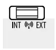
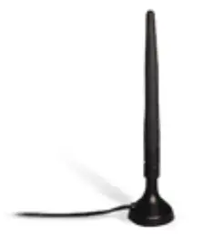
There is an option to connect the 08RFA external antenna to the wiring centre.
If you use an additional antenna, place the jumper in the EXT position. Jumper position change must be refreshed in the memory by pressing the Reset button (short press). - NC/NO actuators jumper

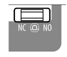
Select the type of the thermoelectric actuator connected to the wiring centre:
NC – actuator normally closed
NO – actuator normally opened Jumper position change must be refreshed in the memory by pressing the Reset button (short press). - ZigBee network coordinator
 The ZigBee network coordination unit CO10RF is used for Offline mode and it’s included with the wiring centre. CO10RF enables wireless control of all devices
installed in one network. Within one network can be connected max 9 wiring centres. It means that if in the network there are more than one wiring centre, you
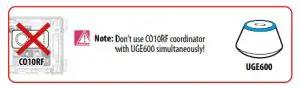
can use one coordinator and put the remaining ones in a safe place. Note: Do not use CO10RF coordinator with UGE600 simultaneously. - Terminals for actuators
Wires of thermoelectric actuators should be plugged into self-locking connectors in appropriate zones. Three actuators can be connected directly to one zone. The current load of one zone is designed to operate up to 3 thermoelectric actuators with a power of 2 W. A maximum of 24 actuators can be connected to the KL08RF 24V wiring centre. Note: On the actuator contacts, there is voltage 24 V AC during their work.
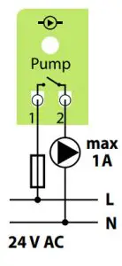
 - Pump control output
Pump output – this is a volt free output (COM / NO) that controls the circulation pump in the heating/cooling system. The output closes (pump starts) always after 3 minutes after receiving the heating/cooling signal from any of the thermostats paired with the wiring centre. The output opens (pump stops) after 3 minutes when the last thermostat stops sending heat / cold demand.
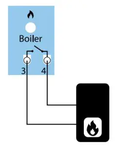
- Boiler control output
Boiler output – this is a volt free output (COM / NO) that controls the boiler in the heating system. The output closes and the boiler turns on but always after 3 minutes after receiving the heating signal from any of the thermostats paired with the wiring centre. The output opens and the boiler switches off when the last thermostat stops sending heat demand (after the time set on the Delay jumper). The output is inactive in cooling mode.
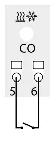
 - CO terminal (input)
Opened CO input contacts (Changeover) means that the whole system works in the heating mode. The short circuit at the input CO will automatically switch the whole system to cooling mode (wiring centre and paired thermostats).
CO terminal Diode Mode  Opened contacts
 Heating
 Closed contacts

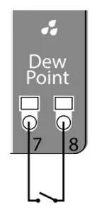
Cooling - Dew point sensor input (humidistat)
 Dew point sensor input is active only in cooling mode (with closed CO contacts).
Shorting the contacts at the dew point sensor input (too high humidity) causes switching off all zones in the wiring centre and Pump control outputs. - Serial connector for the KL04RF 24V extension
It is used for communication between the KL08RF 24V wiring centre and the KL04RF 24V extension module.
KL04RF 24V extension module increases functionality and expands support up to 12 zones.
- External antenna connector
The external antenna connector 08RFA is located underneath the wiring centre under zones 7 and 8. After connecting an additional antenna, place the jumper in the EXT position. Jumper position change must be refreshed in the memory by pressing the Reset button (short press).
 Note: Within one group there may be only one MASTER thermostat (programmable) and the rest must be SLAVE thermostats (non-programmable).
 LED diode statuses:
 – (LED is steady lit) – it means wiring centre is added to the ZigBee network and paired with CO10RF or UGE600
 – Checking the address of the wiring centre in the Zigbee network. To check the address of the wiring centre in the ZigBee network (when using more than one) press the Pair button.
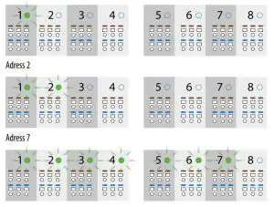
 – The wiring centre reset
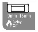
 The ZigBee network coordination unit CO10RF is used for Offline mode and it’s included with the wiring centre. CO10RF enables wireless control of all devices
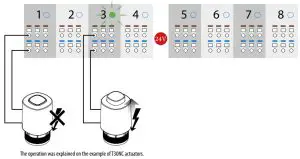

 Heating

MOUNTING
INSTALLATION
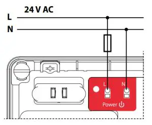
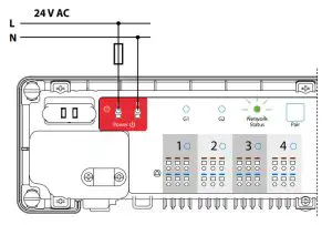
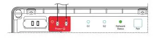
- Connect the wiring centre to the 24 V AC power supply. The Network Status LED will blink.

Online Offline  Note: Do not use CO10RF coordinator with UGE600 simultaneously.
- Wiring centre will connect to the network automatically. The Network Status LED will turn solid green.

Online Offline 

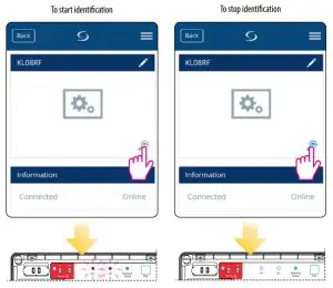
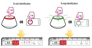
Identification of the wiring centre
To identify the wiring centre in the ZigBee network, follow the steps below:
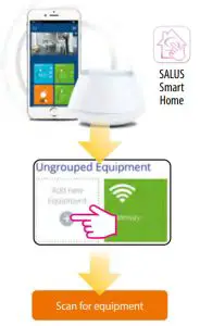
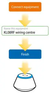
In Online mode (using the SALUS Smart Home app):
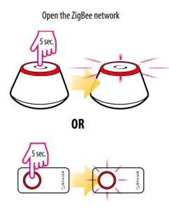
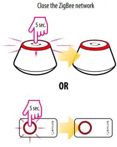
In Offline mode:
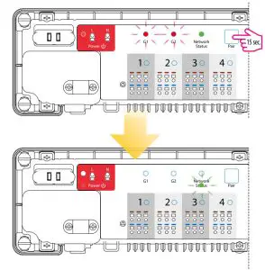
Factory reset
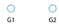
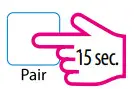
To restore the factory settings, press and hold the Pair button for 15 seconds. G1 and G2 diodes will turn red and go out.![]() Note: If you restore the factory settings of the wiring centre, all paired devices will be removed from the ZigBee network – you will have to synchronize them again.
Note: If you restore the factory settings of the wiring centre, all paired devices will be removed from the ZigBee network – you will have to synchronize them again.
![]() Note: After restoring factory settings, to re-enter pairing mode, click the “Reset” button.
Note: After restoring factory settings, to re-enter pairing mode, click the “Reset” button.
DISTRIBUTOR OF SALUS CONTROLS:
QL CONTROLS Sp. z o.o., Sp. k.
Rolna 4,
43-262 Kobielice,
Poland
Importer:
SALUS Controls Plc
Units 8-10 Northfield Business Park
Forge Way, Parkgate, Rotherham
S60 1SD, United Kingdom

![]()
www.salus-controls.eu
SALUS Controls is a member of the Computime Group.
Maintaining a policy of continuous product development SALUS Controls plc reserve the right to change specification, design and materials of products listed in this brochure without prior notice.
 User Guide")
 24v User Manual")


 230 V User Manual")


 230 V User Guide")


