![]() Wiring center (8 zones) 24 V
Wiring center (8 zones) 24 V
Model: KL08NSB 24V
Manual

SALUS KL08NSB QG V001
Bar Code: 5060103692705
[email protected]
tel: +49 6108 8258515
Head Office:
SALUS Controls Plc
Units 8-10 Northfield Business Park
Forge Way, Parkgate, Rotherham
S60 1SD, United Kingdom
www.salus-controls.com
SALUS Controls is a member of the Computime Group
Maintaining a policy of continuous product development SALUS Controls plc reserves the right to change specification, design, and materials of products listed in this brochure without prior notice.
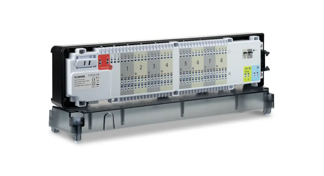
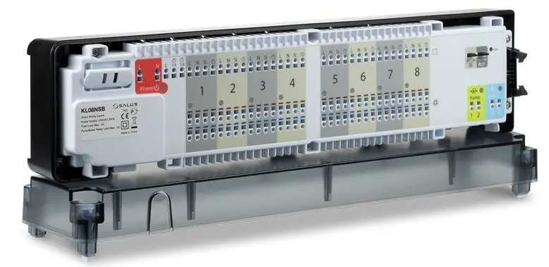
Introduction
The KL08NSB 24V wiring center forms the heart of an Underfloor Heating controls system. It allows easy and quick connection of thermostats and actuators. It has an integrated pump and boiler control module and overload protection. KL08NSB 24V wiring center is adapted to work with NC and NO type actuators (normally closed and normally open). Up to 8 thermostats can be connected to the KL08NSB 24V, while the KL04NSB 24V extension allows connecting additional 4 thermostats (12 in total). NOTE! 24V/230V transformer is included with the set with the control box!
Product compliance
This product complies with the essential requirements and other relevant provisions of the following EU Directives: EMC 2014/30/EU, Low Voltage Directive LVD 2014/35/EU, RoHS directive 2011/65/EU. The full text of the EU Declaration of Conformity is available at the following internet address: www.saluslegal.com. Safety information
Use in accordance with national and EU regulations. The device is intended for indoor use only in dry conditions. Product for indoor use only. Installation must be carried out by a qualified person in accordance to national and EU regulations.
Before attempting to setup and install, make sure that KL08NSB 24V is not connected to any power source. Installation must be carried out by a qualified person. Incorrect installation may cause damage to the wiring center. The KL08NSB 24V should not be installed in areas where it may be exposed to water or damp conditions.
Technical Information
| Power Supply | 24 V AC 50 Hz |
| Total Load Max | 5:00 AM |
| Pump / Boiler Relay Load Max | 3:00 AM |
| Inputs | External clock (24 V) |
| Outputs | Pump control (NO/ COM) Boiler control (NO/COM) Terminals for actuators (24V) |
| Dimensions [mm] | 355x 85x 67 |
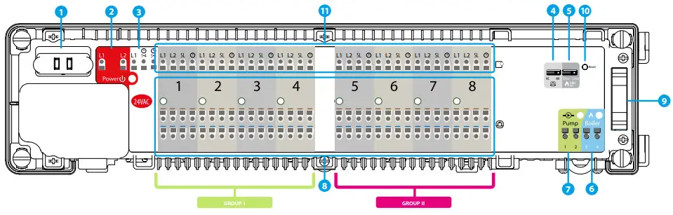
Wiring center description
| 1. Cartridge fuse 5 x 20 mm 12 A 2. Power supply 3. NSB function terminals 4. NC/NO jumper (actuator type) | 5. Delay jumper 6. Boiler control output 7. Pump control output 8. Actuators connection | 9. Serial connector for the KL04NSB 24V extension 10. Reset button 11. Thermostats connection |
Fuse
![]() Note: Replace the fuse only when the wiring center is disconnected from the power supply (24 V ~).
Note: Replace the fuse only when the wiring center is disconnected from the power supply (24 V ~).
The main fuse is located under the housing cover next to power supply terminals and secures the wiring center and the devices connected to it. Use ceramic tube fast blow 250 V ROHS fuses (5×20 mm) with nominal max current 12,5 A. To replace the fuse remove the fuse holder with a flat screwdriver and pull out the fuse.
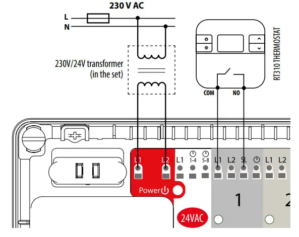
Power Supply
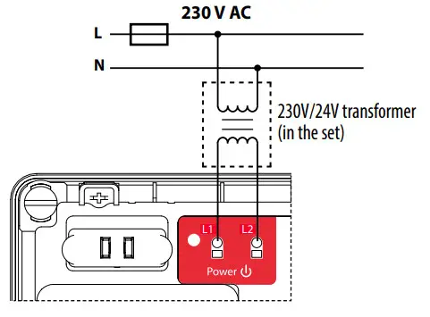
The power supply for the wiring center is 24 V ~ 50Hz.
Two-wire installations should be made in accordance with the applicable regulations
NSB (Night Set Back reduction) function and thermostats grouping
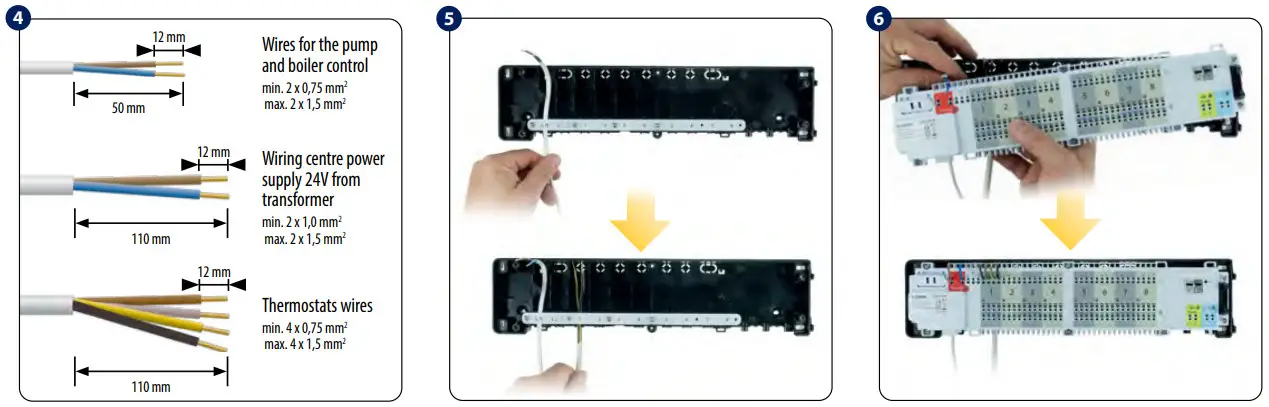
NSB function is activated in non-programmable Salus thermostats of the Expert, HTR series via external signal. NSB 24 V signal (night-time temperature reduction) is sent via an external timer or programmable thermostat connected to the KL08NSB 24V wiring center. Non-programmable thermostats are receiving NSB signals and reducing setpoint temperature (by switching to eco-mode). All thermostats have to be connected using a 4-wire cable (min. 4 x 0,75 mm 2 , max. 4 x 1,5 mm 2 ).
NSB function application in combination with thermostats grouping.
OPTION 1
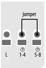
One Master thermostat which is common for thermostats from Group 1 and Group 2 (one programmable thermostat e.g. HTRP(50) 24V, other thermostats are non-programmable e.g. HTR(20) 24V).
OPTION 2
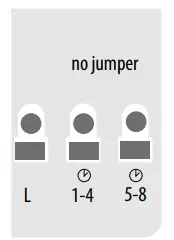
Two Master thermostats. One for Group 1 and one for Group 2 (two programmable thermostats e.g. HTRP(50) 24V, other thermostats are non-programmable e.g., HTR(20) 24V)).
OPTION 3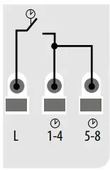
One external clock is common for thermostats from Group 1 and Group 2 (one external clock + daily regulators e.g. HTR(20) 24V)).
OPTION 4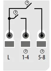
Two external clocks. One for Group 1 and one for Group 2 (two external clocks + non-programmable regulators e.g. HTR(20) 24V)).
NC/NO jumper
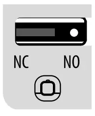
Select the type of the thermoelectric actuator connected to the wiring center:
NC – actuator normally closed
NO – actuator normally opened![]() Jumper position change must be refreshed in the memory by pressing the Reset button (short press).
Jumper position change must be refreshed in the memory by pressing the Reset button (short press).
Delay jumper
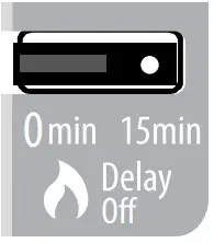
Boiler off delay time. Note: Pump (Pump output) and boiler (Boiler output) always starts 3 minutes after receiving the heating signal from any thermostats connected to the wiring center. Pump stops 3 minutes after the last call for heating sent by the thermostat and the heat source (boiler) will turn off after the time set on the Delay jumper.![]() Jumper position change must be refreshed in the memory by pressing the Reset button (short press).
Jumper position change must be refreshed in the memory by pressing the Reset button (short press).
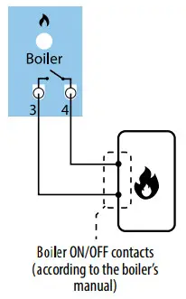
Boiler control output
Boiler output – this is a volt-free output (COM / NO) that controls the boiler in the heating system. The output closes and the boiler turns on but always after 3 minutes after receiving the heating signal from any of the thermostats paired with the wiring center. The output opens and the boiler switches off when the last thermostat stops sending heat demand (after the time set on the delay jumper).
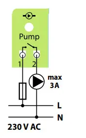
Pump control output
Pump output – this is a volt-free output (COM / NO) that controls the circulation pump in the heating/cooling system. The output closes (pump starts) always after 3 minutes from the moment of receiving the heating/cooling signal from any of the thermostats paired with the wiring center. The output opens (pump stops) 3 minutes after the last demand for heat/cool sent by the thermostat.
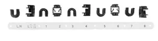
Actuators connection
The actuator wires should be secured with the self-locking connectors in the appropriate zone. Up to 6 actuators with a load of up to 2 Watts each can be connected to a single zone. Should more than 6 actuators be required in a zone use an additional relay to relieve the output?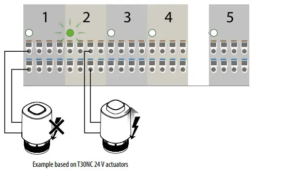 Note: 24 V AC voltage when actuators are live.
Serial connector for the KL04NSB 24V extension
The Serial connector is used to connect the KL08NSB 24V with the KL04NSB 24V extension module to add functionality and support up to12 zones.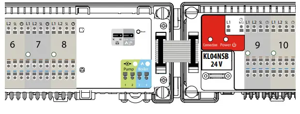
![]() It is used to refresh the data, after switching jumpers 4 or 5.
It is used to refresh the data, after switching jumpers 4 or 5.
Thermostats connection
- Connecting the thermostat of HTR series with NSB function use

- Connecting the RT10 24V thermostat with NSB function use

- Connecting ON/OFF battery-powered thermostat with voltage-free COM / NO output contacts (e.g. 091FL, RT310, RT510)

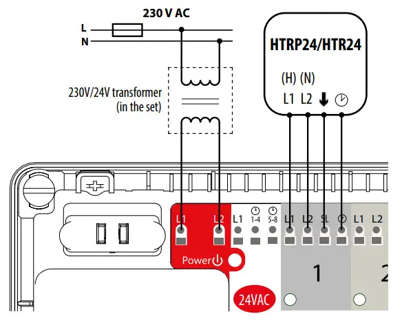
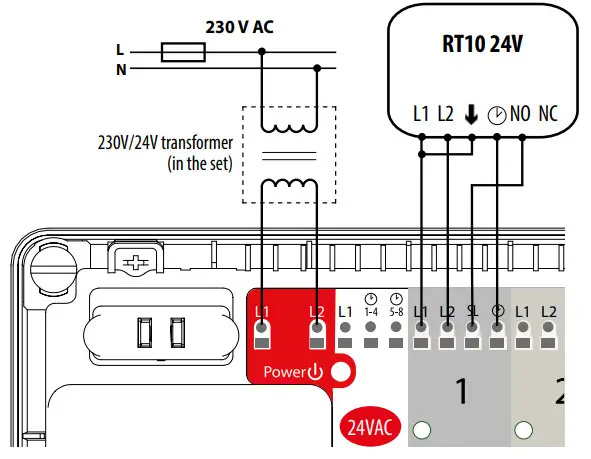
| L1, L2 | 24V AC power supply |
| NSB function terminal | |
| SL ( ↑ ) | The control signal for 24VAC actuators |
Note: In NSB, HTR, ERT, BTR product series follow interchangeable signifying:
↑= SL![]() = NSB
= NSB
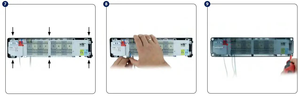
INSTALLATION
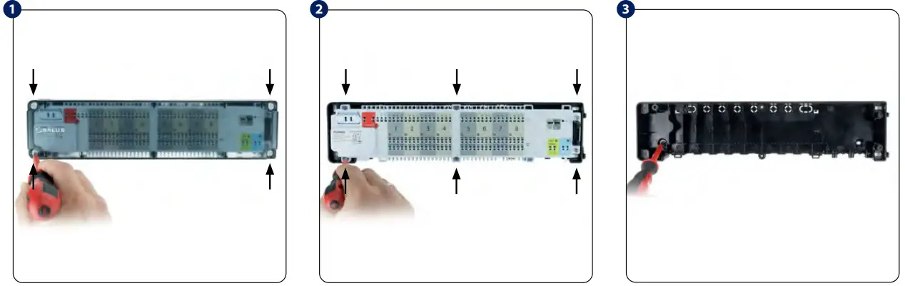
- Remove the top cover of the wiring center.
- Unscrew the main housing (see picture).
- Mount the backside of the housing to the wall. When mounting on a DIN rail, open the hooks on the back of the housing.

- Remove the appropriate piece of insulation from the wires.
- Thread the wires under the mounting belt in the back part of the wiring center.
- Thread the wires through the slots in the top part of the wiring center and connect it to the terminals.
 Set includes supplementary accessories (to support the installation process).

- Adjust the wires and screw the main housing of the wiring center to the rear housing.
- Connect the thermoelectric actuators wires.
- Make sure that all the wires are properly connected, mount the top cover and power up the wiring center – the red power indicator LED will illuminate.

 User Guide")

 24v User Manual")


 230 V User Manual")


 230 V User Guide")


