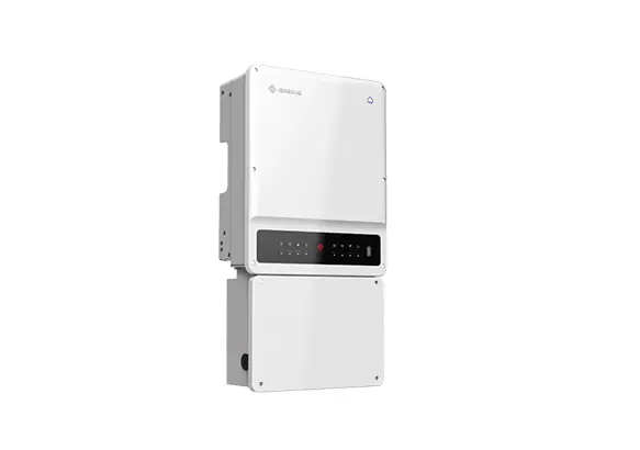
GOODWE A-BP Installation Guide
INSTALLATION INSTRUCTIONS
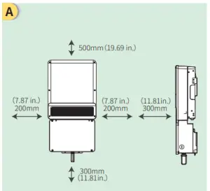
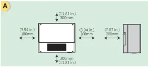
- Installation space
- Upward———-500mm(19.69 in.)
- Downward——300mm(11.81 in.)
- Front————–300mm(11.81 in.)
- Both sides——-200mm(7.87 in.)

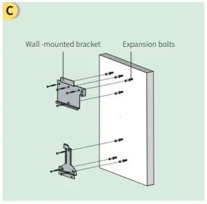
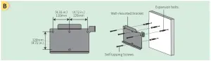
- Dimensions for drilling holes

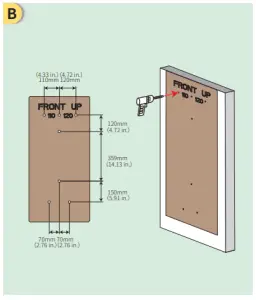
- Fix the wall bracket

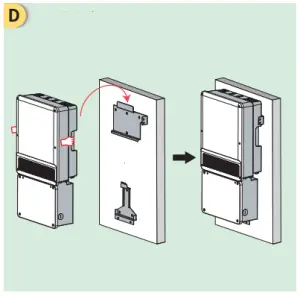
- Install the inverter
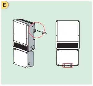
- Fasten screws

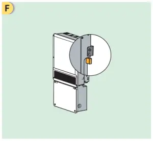
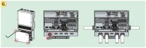
- Inverter could be locked for anit-theft
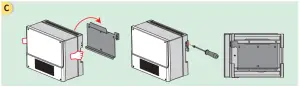
- Wiring Conduit Plugs Connection

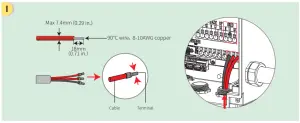
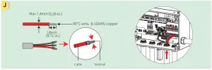
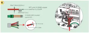
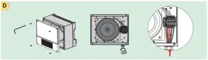
- Battery cable assembly and connection

- On-grid cable assembly and connection

- Back-up cable assembly and connection
- Auto-transformer cable assembly and connection

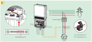
- CT connection

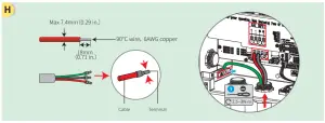
- Battery BMS connection
For CAN1 battery, for example BYD, please connect BMS cables to CAN1 terminals.
For LG battery, please connect BMS cables to 485-1 terminals and connect enable signal cables to LG _EN+ & LG_EN-.
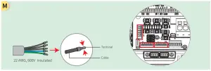
- Plug the WiFi module into the Wifi terminal.


Auto-transformer Connection (Optional)
- Installation space
- Upward ———-300mm(11.81 in.)
- Downward ——300mm(11.81 in.)
- Front ————-200mm(7.87 in.)
- Both sides ——-100mm(3.94 in.)

- Fix the wall bracket

- Installation the auto-transformer
- Auto-transformer connection
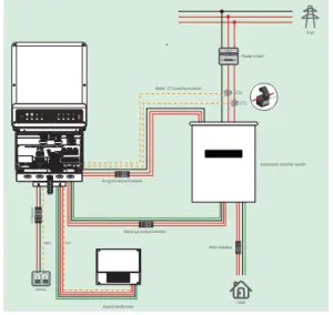
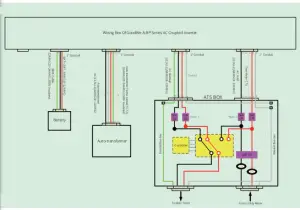
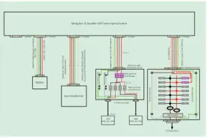
- WIRING SYSTEM FOR A-BP SERIES INVERTER (FULL LOAD)

- SYSTEM CONNECTION DIAGRAM(FULL LOAD)
Note 1: The backup Output L1 or L2 Max continuous current carrying capacity≤40A
Note 2: The actual 50A circuit breaker is installed in this box or other boxes.

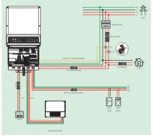
- WIRING SYSTEM FOR A-BP SERIES INVERTER

- SYSTEM CONNECTION DIAGRAM
Note 1: The rated current of the circuit breaker depends on the load power.
Note 2: The Max continuous output current Per Phase @120V is 40A.
Note 3: The back-up Output L1 or L2 Max continuous current carrying capacity≤40A.
- PV Master App

- SEMS Portal App
- SEMS Portal website www.semsportal.com
- LinkedIn
- Offical Website