
TEKBOX TBSCP1-10M500 RF Surface Current Monitoring Probe
Introduction
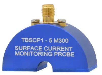
The TBSCP1-5M300 is a RF surface current monitoring probe, expanding the Tekbox product range of affordable EMC pre-compliance test equipment. The probe has a very flat response from 5 MHz to 300 MHz and is characterized over the frequency range from 30 kHz to 400 MHz. The TBSCP1-5M300 is for RF current monitoring applications that need to measure RF currents flowing on surfaces such as PCB groundplanes or traces, metal planes or wires. The footprint of the RF current monitoring probe measures 40 mm x 15 mm. The transfer impedance is -7 dB Ohm with a typical 3dB bandwidth from 5 MHz to 300 MHz.
Specification
- Characterized frequency range: 30 kHz to 400 MHz
- Transfer impedance: -7 dB Ohm with a 3 dB bandwidth from 5 MHz to 300 MHz Suppression of orthogonal field: typ. > 15 dB avg. up to 100 MHz
- Footprint: 40 mm x 15 mm
- Height: 30 mm
- Weight: 25 g
- Connector type: SMA female
- Max. primary current (DC – 400 Hz): 150 A
- Max. primary current (RF): 12 A
- Max. core temperature: 125 °C
Transfer impedance
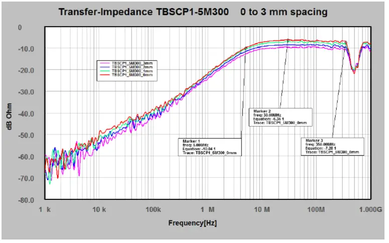
typical transfer impedance, curves for direct surface contact and 1 mm, 3 mm, 10mm spacing between probe and measured surface
Calibration
Place the probe on top of a 50 Ohm microstripline, terminated with 50 Ohm. Connect the microstripline to port 1 of a VNA and connect port 2 to the SMA connector of the probe. Measure S21 and add 34 dB to get the trans-impedance in dB Ohm.
TBSCP1-5M300
RF SURFACE CURRENT MONITORING PROBE
Typical transfer impedance table
The table below shows typical transfer impedance data of a TBSCP1-5M300 current probe. Each current probe is delivered with its corresponding measurement protocol. This data can be used for the creation of a correction file for EMCview or similar EMC measurement software. The transfer impedance in dBΩ subtracted from the analyzer reading in dBµV gives the corrected reading in dBµA.
Refer to the application notes of EMCview on how to create a current probe correction file.
| Frequency [MHz] | transfer impedance [dBΩ] | Frequency [MHz] | transfer impedance [dBΩ] |
| 0.03 | -45.53 | 100 | -6.59 |
| 0.05 | -41.22 | 125 | -6.81 |
| 0.075 | -40.20 | 150 | -6.91 |
| 0.1 | -38.75 | 175 | -6.96 |
| 0.25 | -33.28 | 200 | -7.17 |
| 0. 5 | -27.99 | 225 | -6.66 |
| 0.75 | -24.67 | 250 | -6.92 |
| 1 | -21.94 | 275 | -7.48 |
| 2 | -15.99 | 300 | -6.68 |
| 3 | -13.45 | 310 | -6.82 |
| 4 | -11.38 | 320 | -6.84 |
| 5 | -10.04 | 330 | -6.82 |
| 6 | -9.17 | 340 | -6.91 |
| 7 | -8.48 | 350 | -7.28 |
| 8 | -8.04 | 360 | -8.07 |
| 9 | -7.60 | 370 | -9.19 |
| 10 | -7.38 | 380 | -10.33 |
| 25 | -6.46 | 390 | -11.25 |
| 50 | -6.48 | 400 | -12.21 |
| 75 | -6.78 |
Ordering Information
| Part Number | Description |
| TBSCP1-5M300 | RF surface current monitoring probe, beech-wood box, calibration protocol 30 kHz – 400 MHz |
History
| Version | Date | Author | Changes |
| V 1.0 | 13.7.2022 | Mayerhofer | Creation |
www.tekbox.com
TekBox Digital Solutions Vietnam Pte. Ltd. Factory 4, F4, Lot I-3B-1, Saigon Hi-Tech Park, Tan Phu Ward, District 9, Ho Chi Minh City, Vietnam


