![]()
K40+ Laser Engraver Control Card
User Manual
Read Carefully Before Use Keep for Future Reference
PREFACE
Thank you for choosing this laser control board.
Read this manual carefully before operation. It covers the details of the correct installation, adjustment, and safe operation of your laser’s new control board. It is intended to be used in conjunction with the manuals for your laser engraver and its engraving software. You and any other users of your laser should thoroughly understand ALL these manuals before attempting to install this control system or operate the laser. When correctly installed and used in accordance with these instructions, your laser should operate safely but some components remain extremely dangerous. Be sure that you have correctly connected your laser’s preinstalled safety devices. Never disable or deactivate them. Always use your laser safely and responsibly.
This manual should be included with the others if your engraver is given or sold to a third party. If you have any questions or require more information after reading this manual, please contact us and our support department will address your concerns as soon as possible.
Introduction
Overview
Once you have fully connected this control board to your engraver, you will be able to operate your laser directly from its control panel or through a direct connection with your computer. Designs can also be stored directly on the board’s microSD card, although it is usually impossible to run them directly from standard K40 control panels. For details on the safe use of your laser, see its separate manual. For details on operating your engraving software, see its separate manual.
Symbol Guide
The following symbols are used on this machine’s labeling or in this manual:
 These items present a risk of serious property damage or personal injury.
![]() These items address similarly serious concerns with regard to electrical components.
These items address similarly serious concerns with regard to electrical components.![]() This product is sold in conformity with applicable EU regulations.
This product is sold in conformity with applicable EU regulations. This product contains electrical components that should not be disposed of with regular garbage.
Designated Use
This control board is intended for use with OMTech’s low-wattage laser engravers and cutters using glass (DC) or metal (RF) carbon dioxide (CO) tubes. Its firmware and ports can also be used to control similar engravers from other manufacturers and some CNC machines, although such configurations are outside the scope of this manual and must be done at the user’s own risk. This board must be installed, operated, maintained, and repaired by personnel familiar with its field of use and the dangers both of the machine and its components.
Laser engravers and CNC machines are dangerous. The manufacturer and/or seller bear(s) no responsibility and assume(s) no liability for any improper use of this device or for any damage or injury arising from such use. The operator is obliged to use this control system only in accordance with its designated use and to use its engraver only in accordance with the instructions in all its manuals and all applicable local and national laws and regulations.
Technical Specifications
| Model | K40+ |
| CPU Type | 32-Bit Arm Cortex-M3 |
| Board Dimensions | 3.8×2.8×0.5 in. (9.8×7.3×1.2 cm) |
| Input Power | 24V DC |
| Output Power | 5V DC |
| Max. Clock Frequency | 120 MHz |
| Firmware | Smoothie |
| Compatible Software | LightBurn (Windows/Linux/macOS) |
| System Memory | 512 MB |
| Compatible File Systems | FAT16, FAT32 |
| Maximum USB Speed | USB 2.0 (480 Mbit/sec.) |
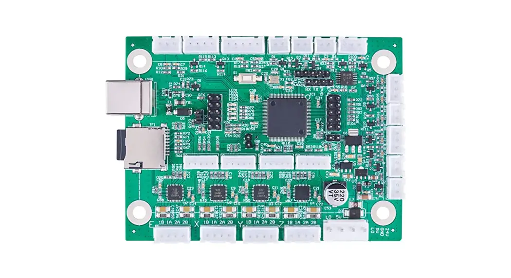
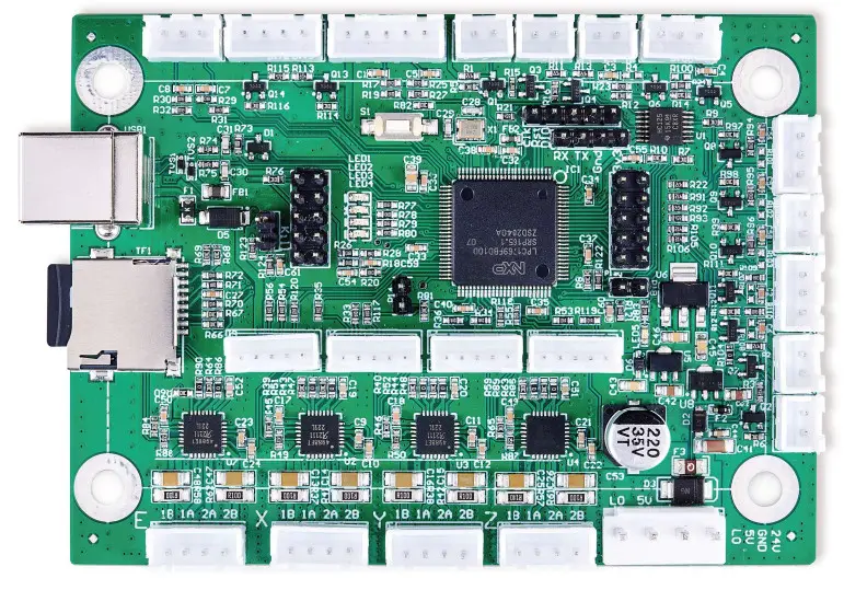
Product Diagram
Control Board
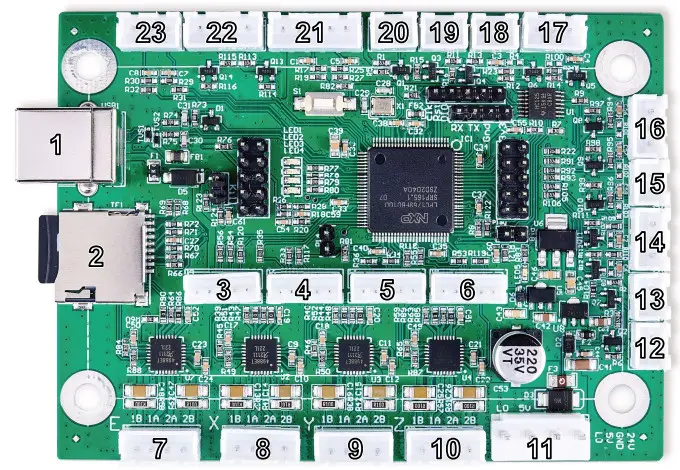
| No. | Label | Pins | Use |
| 1 | — | 4 | USB Type B Computer Connection |
| 2 | — | 8 | MicroSD Card Firmware & Config File Storage |
| 3 | E | 5 | Multiphase U Axis Driver Signal |
| 4 | X | 5 | Multiphase X Axis Driver Signal |
| 5 | Y | 5 | Multiphase Y Axis Driver Signal |
| 6 | Z | 5 | Multiphase Z Axis Driver Signal |
| 7 | E | 4 | MTech or Bipolar U Axis Driver Signal |
| 8 | X | 4 | MTech or Bipolar X-Axis Driver Signal |
| 9 | Y | 4 | MTech or Bipolar Y-Axis Driver Signal |
| 10 | Z | 4 | MTech or Bipolar Z Axis Driver Signal |
| 11 | PWR | 4 | Main Power Connection |
| 12 | BLOW | 2 | Air Assist Signal (5V) |
| 13 | 5V | 2 | 5V Power Output |
| 14 | IN1 & IN2 | 3 | 5V Input Connections |
| 15 | TH5 | 2 | 5V Temp. Sensor Connection |
| 16 | TH3 & TH4 | 3 | 5V Temp. Sensor Connections |
| 17 | TH1 & TH2 | 3 | 5V Temp. Sensor Connections |
| 18 | HE1 | 2 | 5V Temp. Controller Signal |
| 19 | HE2 | 2 | 5V Temp. Controller Signal |
| 20 | FAN | 2 | 5V Add-On Exhaust Signal |
| 21 | X & Y | 5 | X & Y-Axis Limit Switches |
| 22 | Out1 & Out2 | 4 | 5V Output Signals |
| 23 | Z | 3 | Z-Axis Limit Switch |
Safety Information
Disclaimer
Your control board may differ somewhat from those shown in this manual due to options, updates, etc. Please contact us if your device came with an outdated manual or if you have any other questions.
General Safety Instructions
Use this device only in accordance with this instruction manual, the manuals for your laser engraver and its engraving software, and all applicable local and national laws and regulations. Only allow this device to be installed, operated, maintained, repaired, etc. by others who are familiar with these manuals and have read and understood all their warnings and safety information. Ensure that this manual is also included with your engraver if it is ever given or sold to a third party.
- DO NOT install this control board if it arrives or becomes damaged. Contact customer service for help with repair or replacement.
- DO NOT leave this device separate from your engraver or loosely housed within it. Make all connections securely and then firmly secure the device to your engraver’s casing.
- Generally leave the microSD card unmounted except as necessary to update its firmware or to store your designs. If the card is left mounted during engraving, miscellaneous communication between it and your control computer can cause pauses or glitches in your work.
- After any adjustment of this device’s electrical connections with your engraver and its accessories, carefully test that the connections have been made correctly and that the engraver and accessories are responding properly to your commands. Be especially careful of any connections to the water cooling system, heat sensors, and other safety equipment. If your engraver did not come with an interlock sensor that automatically cuts power to the laser when the work bay’s protective cover is opened, it is highly recommended that you get and install one.
Electrical Safety Instructions
- ONLY use this device with a compatible and stable power supply with less than 5% fluctuation in its voltage. If your engraver’s power supply is unable to maintain such consistency, replace the power supply before further use.
- Adjustment, maintenance, and repair of this device and other electrical components of your engraver must be done ONLY by trained and skilled professionals to avoid fires and other malfunctions, including potential radiation exposure from damage to the laser components. Because specialized techniques are required for testing the electrical components of your engraver, it is recommended such testing only be done by the manufacturer, the seller, or a specialized repair service.
![]() Unless otherwise specified, ONLY undertake adjustment, maintenance, and repair of this device and its electrical connections when it, your engraver, and any connected accessories are turned off and disconnected from their power supplies.
Unless otherwise specified, ONLY undertake adjustment, maintenance, and repair of this device and its electrical connections when it, your engraver, and any connected accessories are turned off and disconnected from their power supplies.
- ALWAYS check that the electrical polarities are correct at every stage of installation. Reversing the polarity of power inputs can damage or destroy your board and other components. Use of a multimeter to ensure correct installation is recommended, especially for use with custom projects. Also, ensure that new connections are properly grounded.
- DO NOT allow anything metallic to come into contact with this device while it is powered. Allowing a metal tool or fastener to fall against the board during use can cause short circuits, damaging or destroying the board.
Fire Safety
- NEVER leave your engraver alone during use.
- Always keep a fire extinguisher, water hose, or other flame retardant system nearby in case of accidents. Ensure
the local fire department’s phone number is clearly displayed nearby. In the case of a fire, cut electrical power before dousing the flame. Familiarize yourself with the correct range of your extinguisher before use, as its high pressure can produce blowback. - If installing this board on a CNC machine or other device using thermistors and heating elements, consult www.smoothieware.org and other sources to ensure that your system and its computer code include appropriate safety measures to avoid excessive or uncontrolled heating, with fallbacks and automatic shutoffs in case of errors.
Installation
Unpacking Your Control Board
Your control board and its microSD card should arrive protected by an antistatic bag and insulating foam. If you find any damage during unboxing or installation, please contact us immediately. Do not continue with the installation until customer service can confirm the devices’ safety or provide a safe replacement(s). You may keep the packaging in case of future return but, if you dispose of it or any part of these devices, be sure to do so in compliance with applicable waste disposal regulations.
Preparation
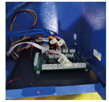
![]() DO NOT install this device while your engraver is connected to its power supply. Turn off your laser engraver and fully disconnect it from its power supply. Open the part of your engraver’s casing that holds its control panel. Place the cover to the side while taking care not to pull or damage its wiring. It is recommended that you use a few pieces of tape to join the various sets of wires connected to your engraver’s current control board. Add labels similar to those shown in the picture below.
DO NOT install this device while your engraver is connected to its power supply. Turn off your laser engraver and fully disconnect it from its power supply. Open the part of your engraver’s casing that holds its control panel. Place the cover to the side while taking care not to pull or damage its wiring. It is recommended that you use a few pieces of tape to join the various sets of wires connected to your engraver’s current control board. Add labels similar to those shown in the picture below.
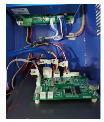
Here, “PWR” is used for the main power input, “Y” and “X” for the motor drivers, and “END” for the limit switches. Any clear phrasing is fine. If your old board already has other connections in addition to these, use its manual or the board’s markings and the diagram in §1.5 to label those wires as well. Once all connected wires are clearly labeled, disconnect them from the old board.
Replacing the Old Control Board
Remove the three bolts holding the control board plate to your engraver. Remove the plate and remove the four bolts at the corners of the old control board.
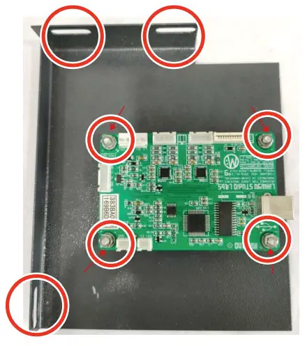 You can mount the new control board into place now (being careful to position its USB port beside your casing’s access hole) or make all the necessary electrical connections first before bolting it into place.
Electrical Connections
![]() Only install this board while your engraver and all components are turned off and disconnected from power. Always check that the polarities of your connections are correct, with a multimeter if needed.
Only install this board while your engraver and all components are turned off and disconnected from power. Always check that the polarities of your connections are correct, with a multimeter if needed.
Control Board Power
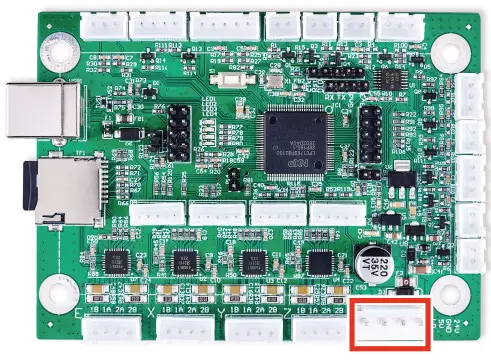
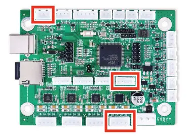
On the control board, find the largest 4-pin terminal. Connect the “PWR” terminal block previously removed from your old board to this terminal. If you are connecting the wires individually for a new or different system, connect the pin marked “24V” to your engraver’s 24V power supply and the pin marked “GND” to the power supply’s ground port, sometimes marked “0V”.
Laser Tube Connection
This control board does not directly connect to your laser tube.
Laser Head Connections
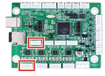
On the control board, find the 4 pin terminals marked “X” and “Y” beside the power terminal just connected. Connect the “X” and “Y” terminal blocks previously removed from your old board to these terminals. If you are connecting the wires individually for a new or different system, bipolar stepper motors will use the same four-pin terminals. Connect the two wires coming from either coil to the pins marked “1A” and “1B”. Connect the two wires from the other coil to the pins marked “2A” and “2B”.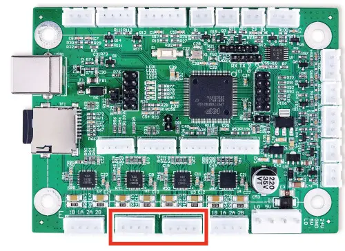 The 5 pin terminals marked “X” and “Y” in the center of the board might be necessary for some upgraded stepper motors. You can connect them directly to a preassembled terminal or wire them separately. Connect each pin marked “5V” to the positive pins (“PUL+”, “DIR+”, and “EN+”) for the corresponding axis. Connect each pin marked “GND” to the corresponding ground (“GND” or “0V”) pin. Connect the pins marked “STP”, “DIR”, and “EN” to the corresponding negative pulse (“PUL-“), direction (“DIR-“), and enable (“EN-“) pins respectively.
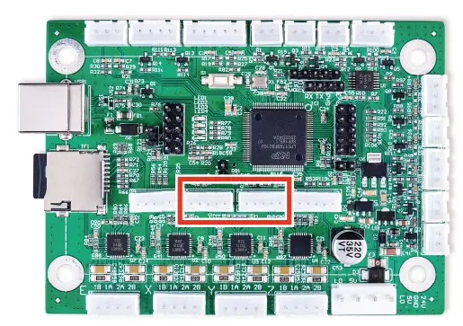
Device Input Connections
This circuit board can accept two separate 5V input signals from devices such as an interlock open cover sensor or a foot-controlled power switch. (If your engraver did not come with an interlock sensor, it is strongly recommended that you install such a sensor.) You can connect preassembled 3-pin terminal blocks to the central terminal across from the USB and microSD card ports or wire them separately. Connect the live wire to either of the outer pins (“IN1” or “IN2”) and connect the grounds to the central pin (“GND”).
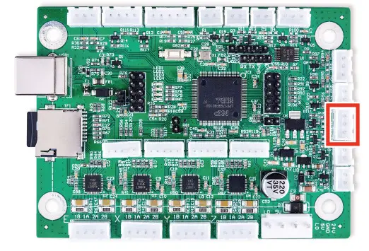
The 2 and 3-pin thermistor terminals (“TH1″” TH5″) can provide similar 5V inputs from CNC thermistors or other sensors. Each accepts one or two input lines and a ground line (“GND”) between or to the right.
Limit Switch Connections
On the control board, find the 5-pin terminal along the side next to the USB port. Connect the “END” or “LMT” terminal block previously removed from your old board to this terminal. If you are connecting the wires individually for a new or different system, connect the pin marked “Y-” to your Y-axis limit switch. Connect the pin marked “X-” to your X-axis limit switch. Connect the “GND” pins to the ground connections for the corresponding limit switch.
Device Output Connections
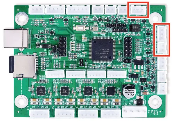
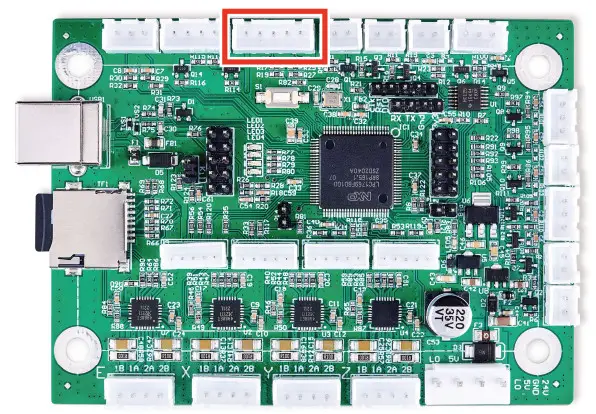
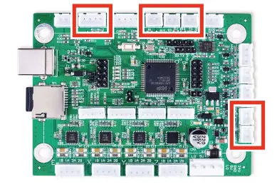
This circuit board can provide a 5V power feed and up to nine 5V output signals to control various ancillary devices such as external exhaust fans, pressurized air assists, and CNC heating elements. The power feed terminal has 2 pins for the current (“5V”) and the ground (“GND”). The output signal terminals accept 2, 3, or 4 pin terminal blocks and are variously labeled “FAN”, “BLOW”, “HE1” and “HE2”, and “OUT1” and “OUT2”. Each has a line pin and a shared or separate ground pin (“GND”).
Worked Connections
To install an automatically adjustable work for your engraver, follow the instructions in §3.4.3 to connect its stepper motor to either the outer 4 pin terminal or the inner 5 pin terminal marked “Z”. Connect its limit switches to the “Z+”, “GND”, and “Z-” pins in the corner terminal next to the USB port.
Rotary Axis Connections
To install a rotary axis, follow the instructions in §3.4.3 to connect its stepper motor to either the outer 4-pin terminal or the inner 5-pin terminal marked “E”.
Data Connections
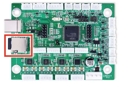
The microSD card goes into its port on the side of the card. The pins on the card should face down and go in first. The slightly raised handle should face up and protrude slightly after insertion. Do not force the card into place.
 If you did not already do so, bolt your new control board to its holding plate, making sure that the USB port will face the casing’s access hole. Slide it back into your engraver and bolt the holding plate into place inside the casing.
Use your type-B USB cord to connect the card to your control computer. It is recommended that you configure your machine not to automount the control board’s microSD card. Again, leaving it mounted during engraving can lead to unexpected pauses and glitches when the control computer periodically reads and writes to it.
Software Configuration
Device Drivers
For most editions of Windows, you will need to download device drivers to allow the control computer to recognize and communicate with your new motherboard. Go to www.smoothieware.org/windows-drivers and follow the instructions there. For Linux and macOS systems, no drivers are required but if you experience problems or excessive lag when using your control board, the “Linux Drivers” and “Mac Drivers” pages at www.smoothieware.org provide guidance on improving your system’s configuration.
LightBurn Setup
To use your new control board with LightBurn, go to the Layer menu and select Devices. Select Create Manually in the submenu that will pop up.
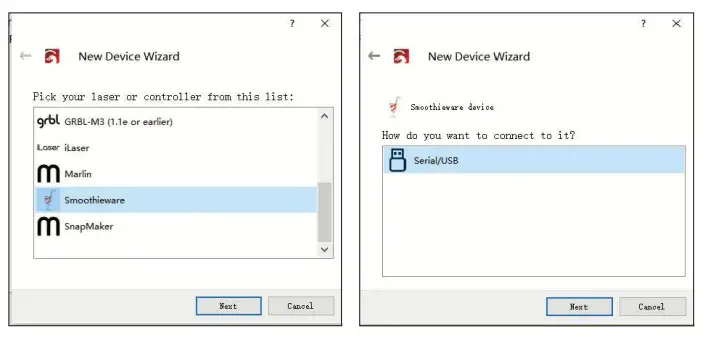
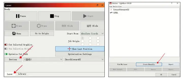 Scroll down the pull-down menu that will appear and select “Smoothieware”. In the next menu, select that you will connect to it using “Serial/USB”.
 Choose a name for your engraver (“Smoothieware” in the example picture) and enter the length of your laser engraver’s X and Y axes in millimeters. Enter the origin for your machine (select “Rear Left” for OMTech engravers) and select whether you want LightBurn to return the laser head to the origin at startup. Review the information that you have entered. Select Cancel and correct any misinformation or select Finish.
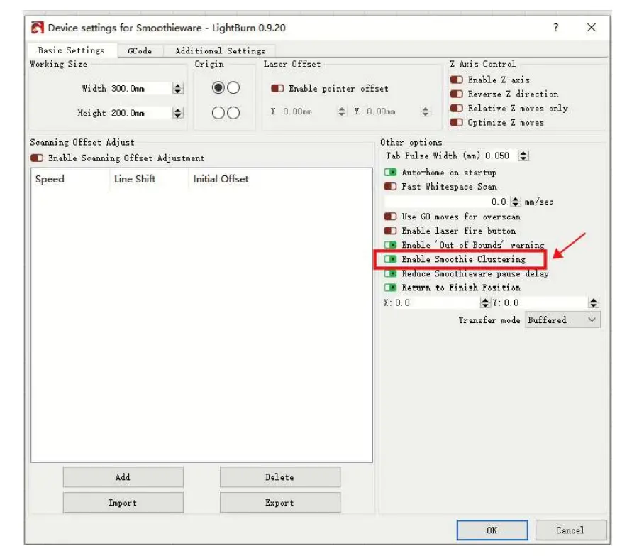
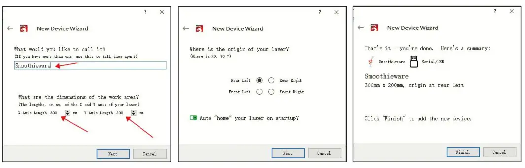 After LightBurn finishes installing its connection to your engraver’s new control card, go to the Edit menu and select Device Setting. Under the Basic Settings tab, find the Other Options section and activate Enable Smoothie Clustering.
Testing
Restore power to your engraver and test that all of its safety features remain fully functioning. Test that the control panel and control computer are able to move the engraver’s laser head and fire the laser correctly. Correct any problems before further use, making sure to fully disconnect the engraver from its power supply before making any adjustments. Contact technical support or customer service if any problems remain or arise after installation.
Maintenance
Always disconnect your engraver from its power source before any adjustment, cleaning, or other maintenance of these devices.
You can remove dust from these devices with a soft cloth. Do not use harsh chemicals or allow any electrical components or connections to become wet. If they accidentally become wet, immediately use your engraver’s emergency stop button, disconnect your engraver from its power source, and leave it disconnected until all water has completely dried.
If there is ever a need to replace the provided microSD card, format it to use the FAT32 file system.
For maximum safety and best results, leave all other adjustments, maintenance, and repair to trained and skilled professionals. If this control system is ever damaged or malfunctions during use, immediately use your engraver’s emergency stop button, disconnect your engraver from its power source, and leave it disconnected until all damage
or malfunctioning equipment has been fully repaired or replaced.
Contact Us
Thank you for choosing our laser equipment for your home or shop! For a .pdf copy of the latest version of this manual, use the appropriate app on your smartphone or other device to scan the QR code to the right.
Come join the OMTech community at our official laser group on Facebook or visit the company forums at omtechlaser.com! Check our YouTube channel for helpful hints and instructional videos. If you encounter any problem regarding your engraver, do not hesitate to contact customer service with your order number at [email protected] or [email protected]. Our teams will respond within 24 hours to make things right. You can also reach us Monday to Friday at (949) 539-0458 between 8 am and 4:30 pm PST.

Thank you and we hope you will choose us again for all your laser needs!
USB-K40S-00
Rev. 15 Feb. 2022


