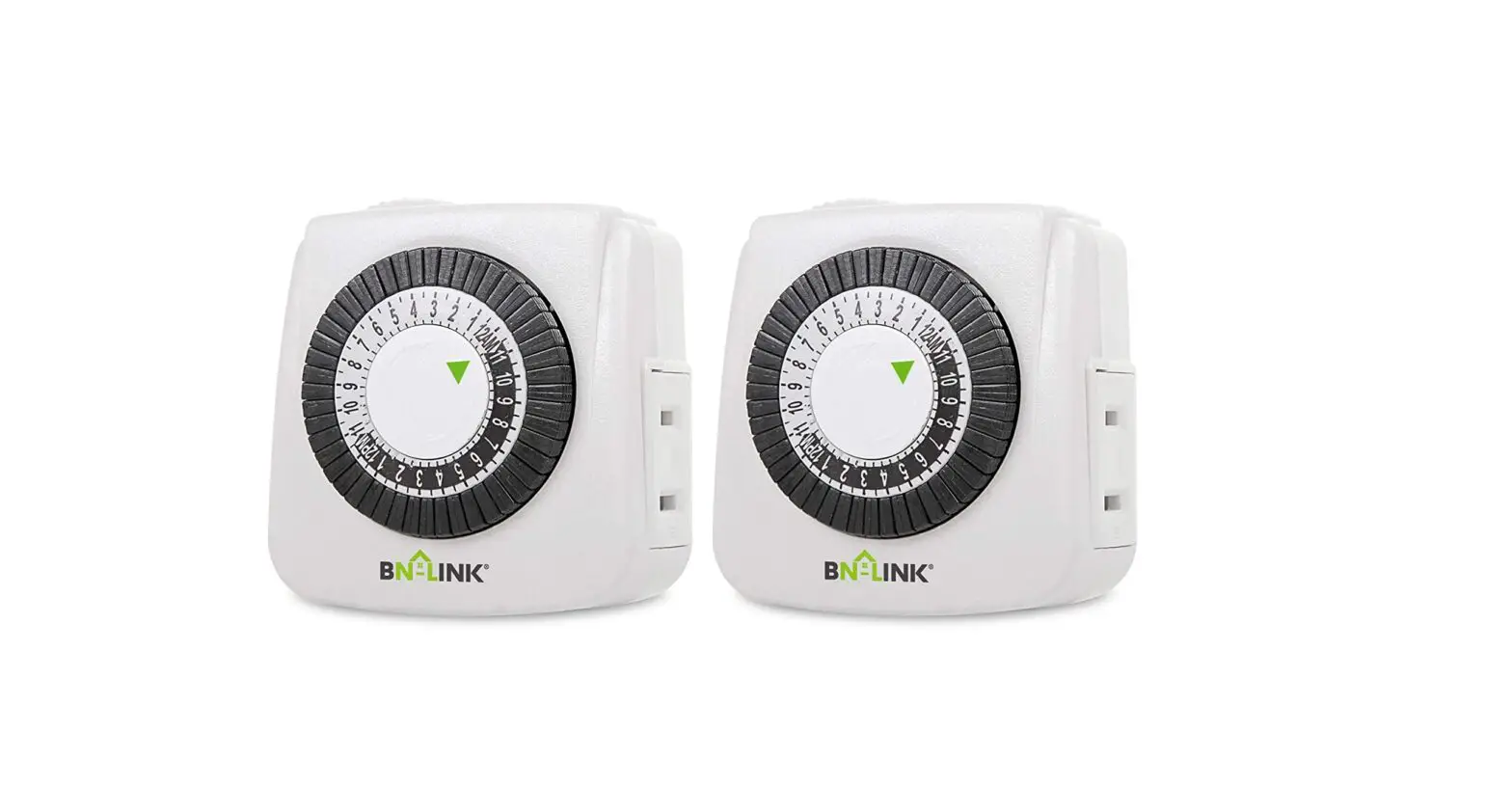
BND-60/U44 24 Hour Mechanical Mini Timer
BN-LINK PRODUCT #BND-60/044
24 HOUR MECHANICAL
MINI TIMER
Please keep this handbook
PRODUCTS VIEW
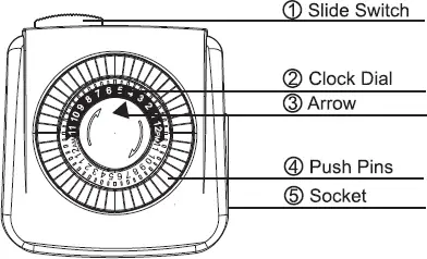
① Slide Switch: Slide the switch left to “![]() ” icon position for timing. Slide the switch right to “ON” for always ON.
” icon position for timing. Slide the switch right to “ON” for always ON.
② Clock Dial: Black Part=12PM-12AM Hours: White Part=12AM–12PM Hours.
③ Arrow: Indicates the current time of day. Push Pins: Each pin represents 30-minute. Pins down = ON; Pins up = OFF.
④ Socket: Only intended to be used with a 2-prong outlet device.
RATINGS
Rated Voltage: 125V, 60Hz
Max. Loading: 1875W, 15A Resistive, 8A Tungsten, 1/2HP,TV-5
WARNING
- Electrical shock hazard.
- Follow local electrical codes.
- For indoor use only
- Keep children away
- Unplug timer before cleaning
- Fully insert plug.
- Do not use in wet locations.
- Do not exceed electrical ratings
APPLICATIONS
- Lighting.
- TV.
- Humidifiers
- Nebulizers
- Automates fans
- Indoor sprinklers
- Aquariums
- Ventilators
OPERATING INSTRUCTIONS
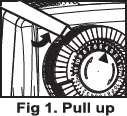 Step 1. Pull all black pins to upper position
Note: The pins are in down position when taken out of package.
Step 2. Set a period of time for the unit to be “ON” Locate the black pins 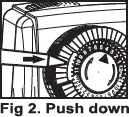 and push them down at the marked times when the attached device is to be “ON”. Each pin represents a Push down 30–minute time interval.
Note: Make sure all pins are in the upper position before beginning. Example: “ON” time is 9:00PM, “OFF” time is 12:30AM. Push down all of the pins between 9:00PM and 12:30AM.
Note: Pins are black slices around the dial.
Step 3. Set the “CURRENT TIME” Rotate the entire black push–pin dial clockwise until the arrow aligns with the current time of day on the dial. Example: It is 4:00PM, please rotate the dial clockwise until the arrow aligns 4PM on the dial.
Note: Please pay attention to AM/PM.
ON
Step 4. Set “BYPASS SWITCH” When the switch is in the “@” position, the unit will automatically turn your attached device ON and OFF according to the programmed time. When the switch is in the “ON” position, Fig 4 the unit will bypass the programming and your attached device will remain ON.
Step 5. Plug the unit into an electrical outlet The unit will rest against the outlet.
Step 6. Attach one device to the unit Plug the device into the outlet on the side of the unit. Make sure the attached device is switched ON.
HELPFUL TIPS
- This timer repeats the same settings daily.
- To push down or pull up the black pins, use your finger or the tip of a small instrument such as a pen or pencil.
- You can set up to 24 different “ON” and “OFF” times in a 24–hour period. Pins pressed down represent the “ON” time, pins in the up position represent “OFF” time.
- Switching the unit to “ON” will bypass programming, however, the timer dial will continue to rotate and maintain the current time.
- Unit will stop operating if the power goes out.
Once power is resumed, reset the time of day as explained in Step 2 of the instructions.
TROUBLESHOOTING
- PROBLEM: Appliances do not turn on as programmed.
- POSSIBLE CAUSE: Connected appliances are not in “ON” position; they are not functioning; timer is not receiving power, or “BYPASS SWITCH” is in the “ON” position.
CORRECTIVE ACTION: Ensure the connected appliances are functional by plugging them directly into the outlet. Be sure the connected appliances are in the “ON”position if they have their own switch. Make sure the power outlet from which the timer is plugged into is active. Check that the “BYPASS SWITCH” is in the “e” position.
- PROBLEM: Appliances come on before the actual time.
- POSSIBLE CAUSE: “CURRENT TIME” was not set properly.
- CORRECTIVE ACTION: Refer to step 2 of this manual. Be sure “CURRENT TIME” is set in the white section on the timer dial if the “CURRENT TIME” is in the “AM.” The “CURRENT TIME” should be set in the black section on the timer dial if the “CURRENT TIME” is in the “PM.” .
- PROBLEM: The pins can not be pushed down.
- POSSIBLE CAUSES:
- The pins are already in ‘DOWN‘ position. 2.The pins are blocked by the inner mechanism of the slide switch.
- CORRECTIVE ACTIONS: 1.Pull all pins up with a pen or a similar tool before setting operation. 2.Slide the switch to ‘ON’ position.
BN-LINK INC.
12991 Leffingwell Avenue, Santa Fe Springs Customer Service Assistance: 1.909.592.1881 E-mail: support@bn–link.com Http://www.bn–link.com Hours: 9AM – 5PM PST, Mon – Fri Designed in California Made in China


