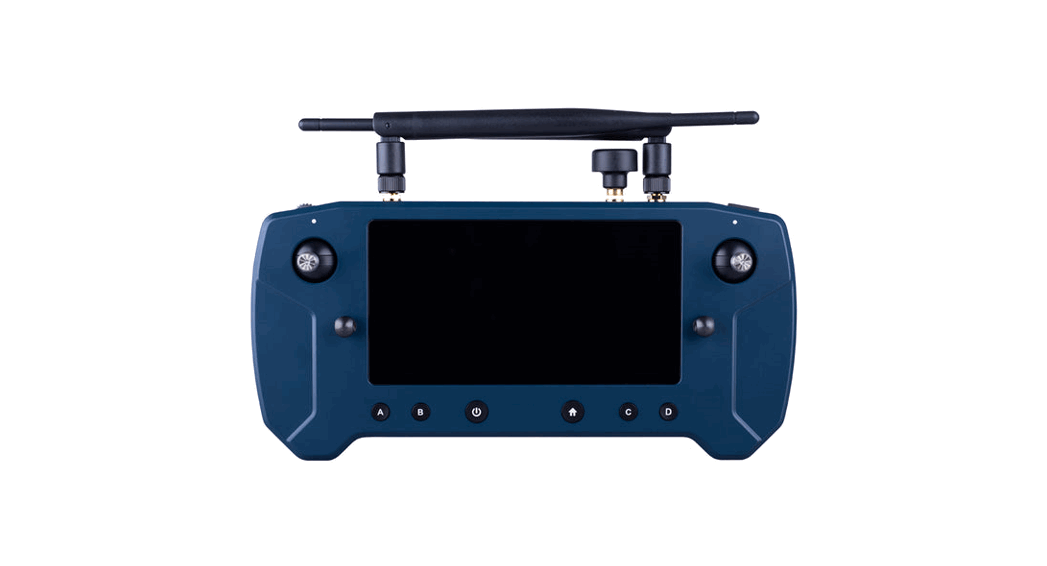
![]() 1001 Herelink Blue Controller Unit
1001 Herelink Blue Controller Unit
User Manual
HLBC 1001 Herelink Blue Controller Unit
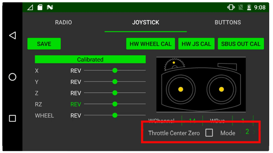
Click the JOYSTICK tab to access the joystick screen.
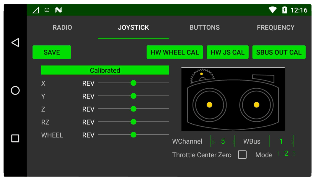
Here you will find the sticks and hardware wheel options and calibration settings.
From this screen you can:
- See RC Calibration Status
- Calibrate Hardware Wheel
- Calibrate Sticks
- Set RC Stick Mode
- Set Hardware Wheel Sbus Channel & Bus
- Reverse RC Channel
- Set Throtde Centre Behavior
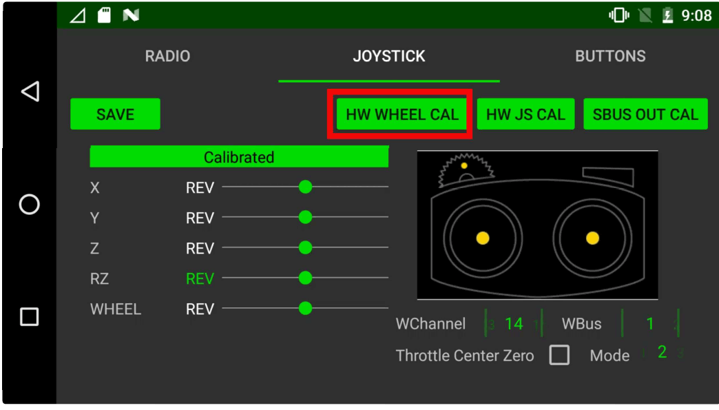
Calibrate the hardware wheel
Select HW WHEEL CAL
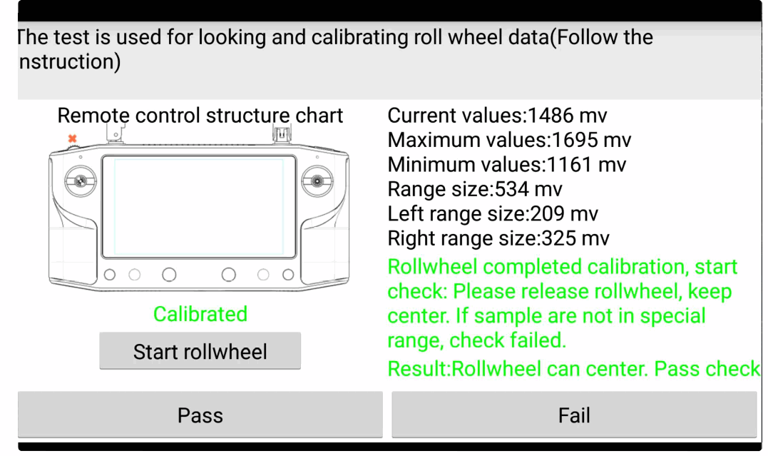
Click St a rt rollwheel and follow the calibration steps.
Note once complete you can check its correct ftinctioning by looking at the values change, click Pass to return to joystick screen.
Once calibration is complete you can set the Sbus channel output and Bus output for the wheel on the highlighted settings.
BUS 1 is the same output as the sticks and the wheel can be set to channels 5 -16, on bus 2 the wheel can be set to channels 1 -16.
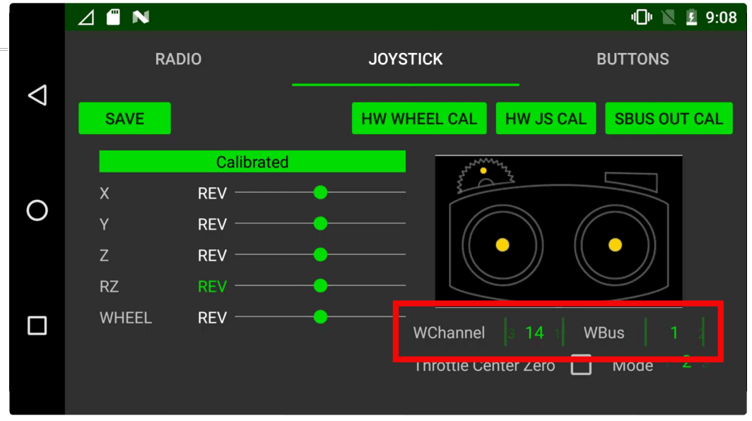
Once complete click SAVE to store settings
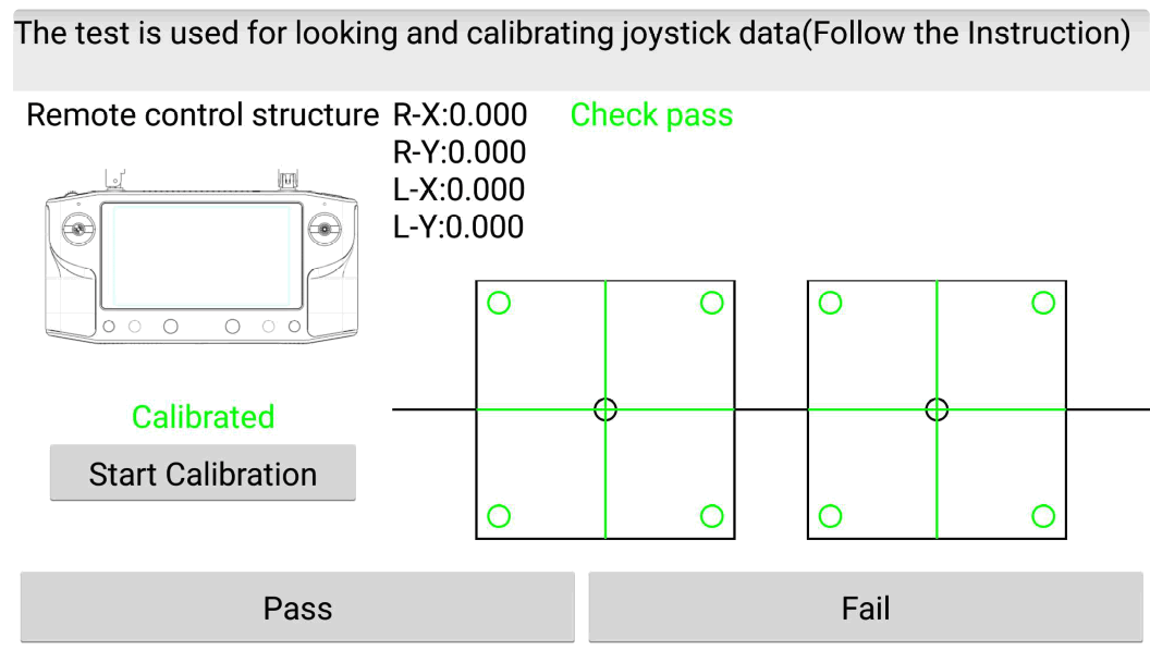
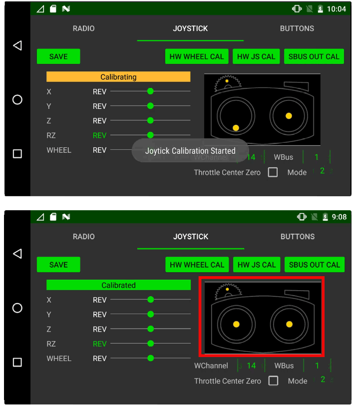
Calibrate the joysticks
Click HW JS CAL
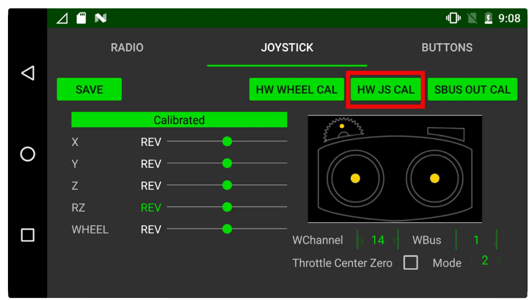
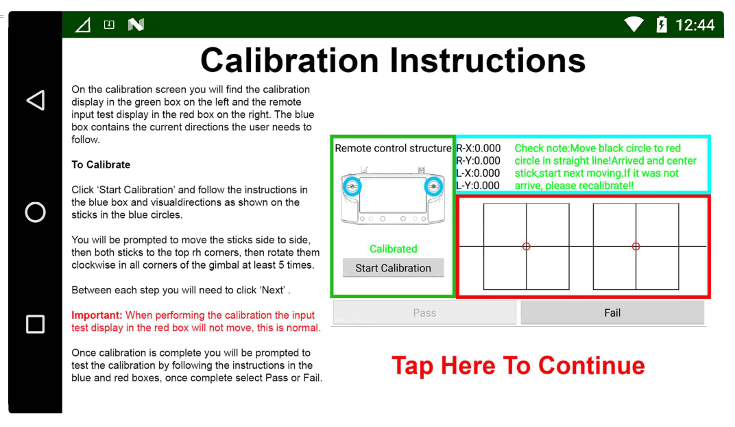
This screen is split into 2 sections, joystick calibration on the left, joystick testing on the bottom right, instructions for the user to follow will be shown in the green box. Click Start Calibration to begin the process and follow the instructions in the green box and the sick movement arrows located around the Sticks on the remote as highlighted in red below.
Note: The joystick testing area in the bottom right will not move or show any input while you are calibrating the sticks. This is normal, this area will only display input after the joysticks have been calibrated.
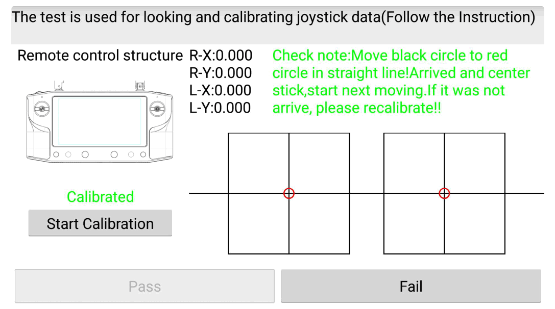
Once the joystick calibration step is complete the input test area in the red box will activate, follow the instructions above it to test the sticks input are functioning correctly by aligning the black and red circles in each step shown. This will test the joysticks are moving correctly in all axises.
At the end of this process if you are happy with the input behavior you can click ‘Pass’ and the calibration will be stored, if you’re experiencing any issues click ‘Fail’ and start the calibration process again using a little more pressure in the corners.
RC Mode Selection , Throttle Behavior & Channel Reversing
DataLink supports RC modes 1-4 as well as the option to Set the throttle centre as zero PWM output and reverse each channel.
Set throttle center and RC mode via the below settings.
The stick sbus output can be reversed by clicking on ‘REV’ next to the channel you want to change.
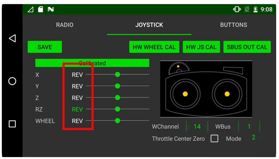
After making any changes click SAVE to store settings.
Calibrate SBUS Output
To calibrate the joystick SBUS outputs click SBUS OUT CAL.
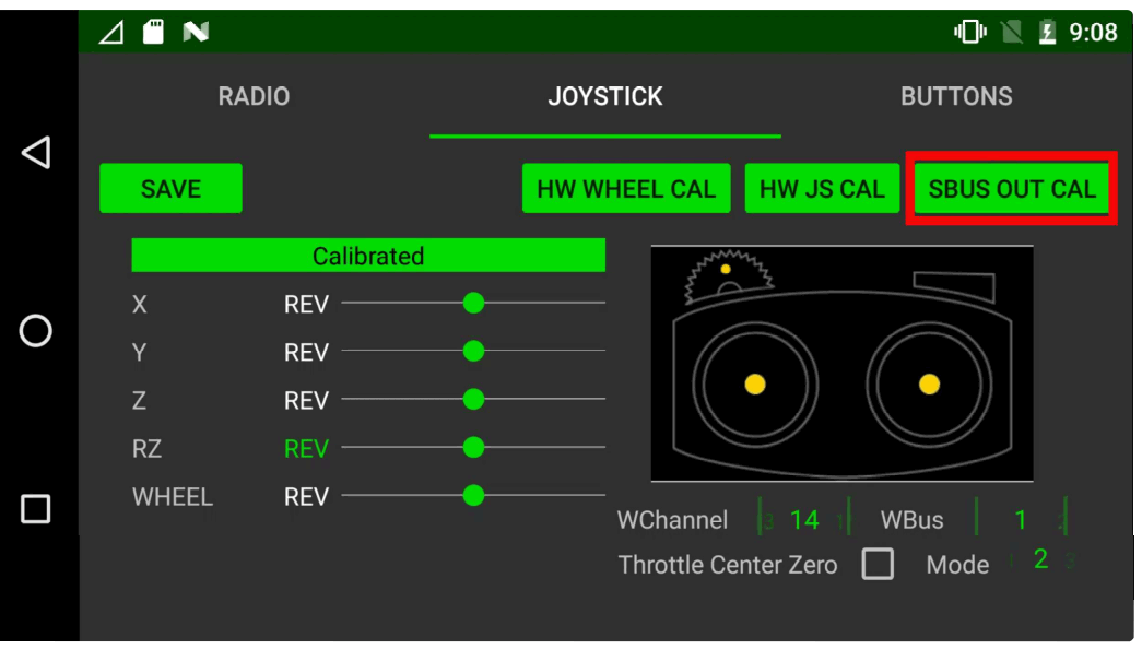
Follow the RC stock movement steps as shown in the highlight section moving the stick through each position.
Once complete click SAVE to store settings.
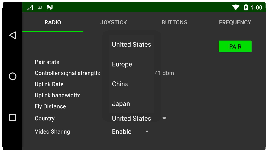
Selecting FCC/CE settings
Select the region you are residing in or matches closest to your locations policy from Country Under “Union Robotics Settings” main screen.
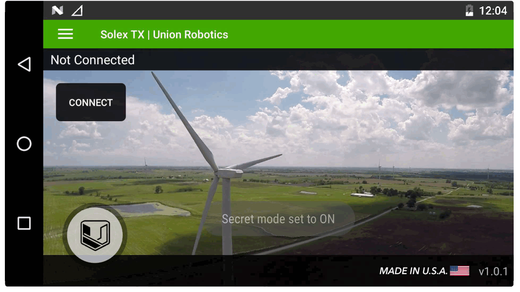
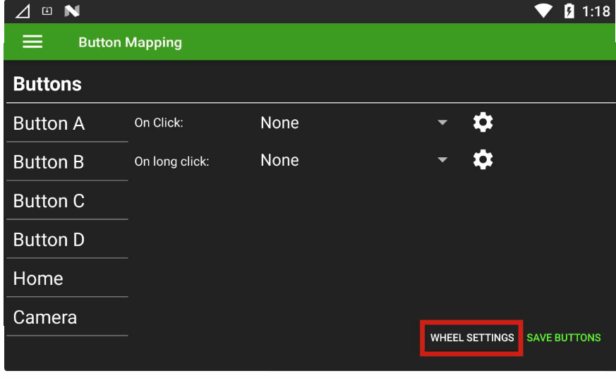
Button Mapping
To configure buttons, the “Secret Mode” needs to be set to ‘ON’.
Open the UR/Solex TX App
Press and hold the Version number at the bottom right of the screen for 5 seconds.
On release, the “Secret mode set to ON” message should appear.
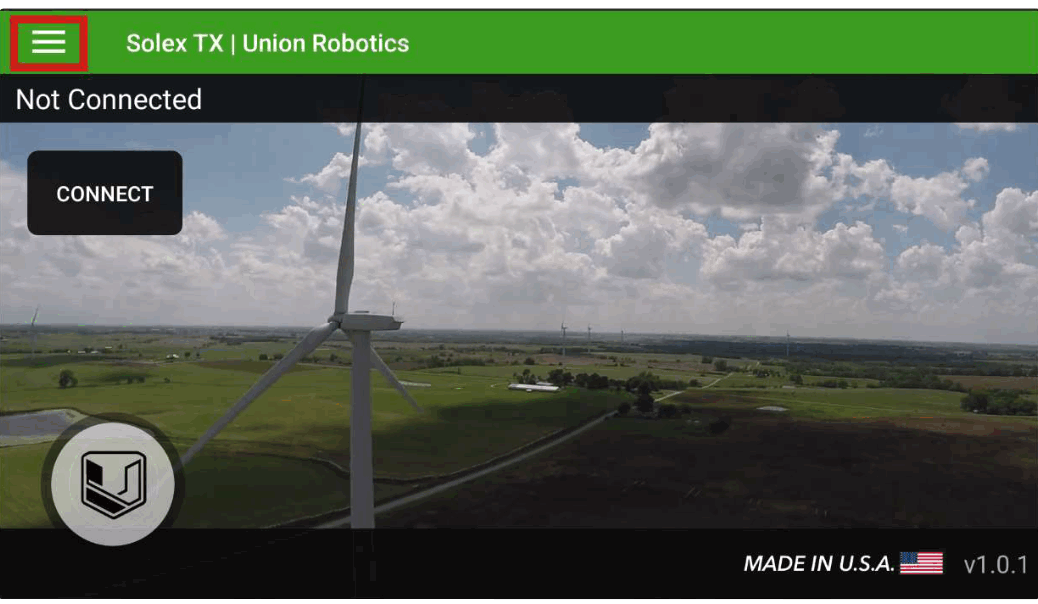
Click the hamburger menu icon in the top left corner
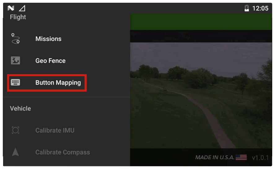
Select Button Mapping
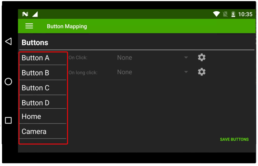
Choose desired button
Select either Click or Long Click (Note this allows you to set two functions to each button)
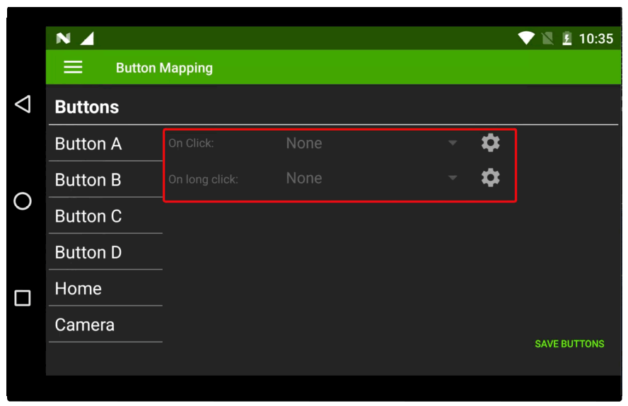
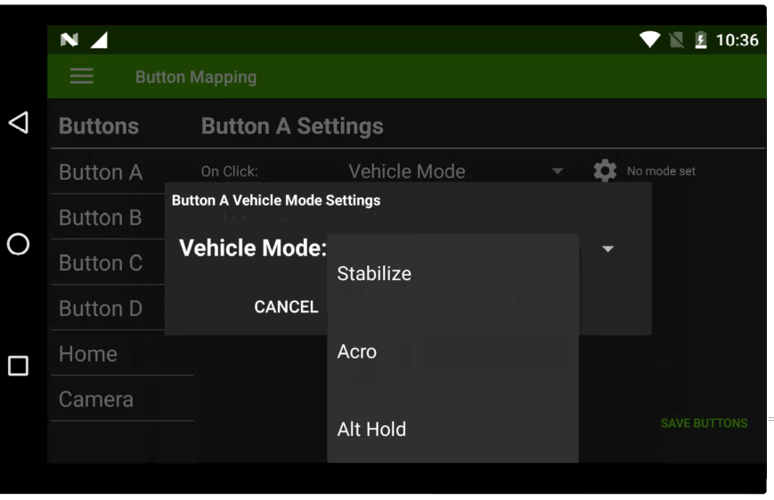
Click on drop down to select the function you want
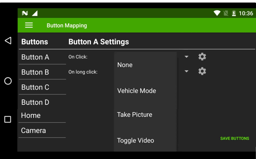
Click on small cog to select option with-in selected function
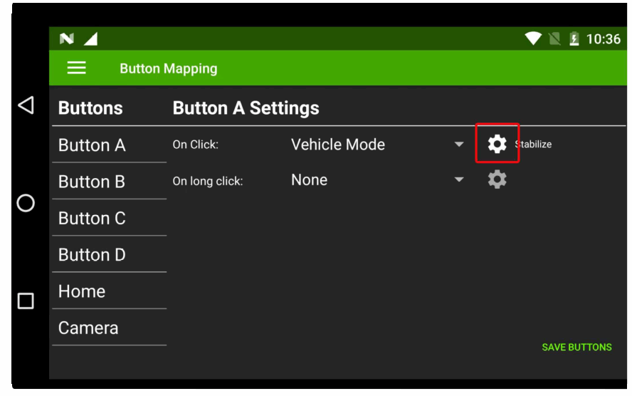
Select function option
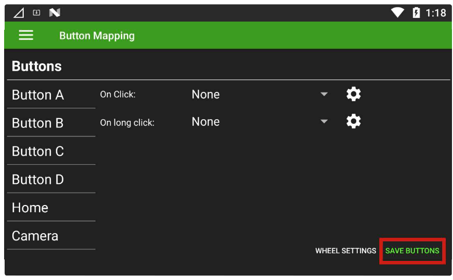
Repeat for each button assignment and click SAVE BUTTONS in bottom comer to finish
Hardware Wheel
The hardware wheel is mapped to SBUS channel 5 by default but can also be configured in UR/Solex TX to
Servo output channels 1-16 on the Autopilot, you also have the ability to switch the servo output via a button in UR/Solex TX.
To Configure Wheel in Solex TX
- Open UR/Solex TX App
- Click the hamburger menu icon in top left corner
- Select Button Mapping as above
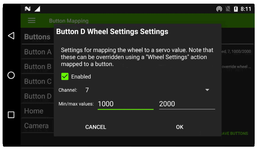
- Click WHEEL SETTINGS in the bottom right corner
Select the desired servo channel from 1- to 16
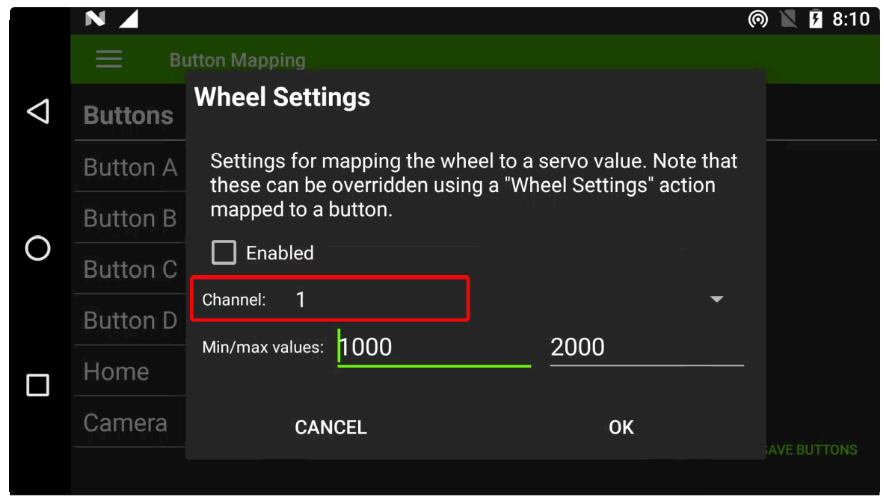
Select the PWM output range for your application
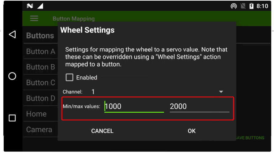
Click the Enabled box to activate the output
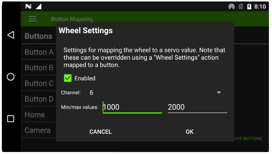
Finish by clicking OK and click SAVE BUTTONS in bottom corner
To configure a button to change the wheel servo output configure the button to WHEEL SETTINGS
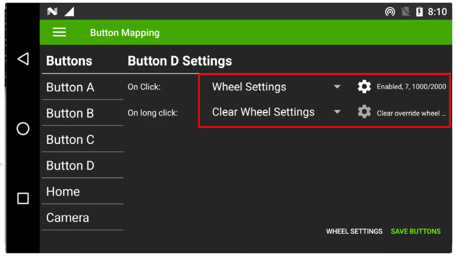
Click the cog and set new channel and PWM values and click OK and then SAVE BUTTONS in bottom right corner.
Once changed the wheel will output on the new selected channel, to return to its original servo output you will need to program one button function to Clear Wheel Settings as shown above.
Configure Sbus Buttons & Wheel
DataLink is fitted with six programmable buttons and one hardware wheel. These can be configured to control sbus channel outputs from the Rover Unit’s dual sbus connector and to send Mavlink commands to the autopilot via UR/Solex TX.
Autopilot Mode Selection – Important
Autopilot mode selection must not be programmed to sbus channels. Mode selection should be configured to Mavlink commands within UR/Solet TX to ensure predictable behavior in the event of signal loss.


