VAISALA CAB100 CMS Industrial Cabinet
Product Overview
Vaisala CMS Industrial Cabinet CAB100 is an instrument cabinet designed to integrate devices for measuring humidity, temperature, differential pressure, and other parameters.
CAB100 is available in 2 models, CAB100A (small enclosure) and CAB100B (large enclosure). The cabinets can be configured according to application requirements, with options for differential pressure transmitters, analog input channels for the connection of remote transmitters, and safety barriers or galvanic isolators for hazardous areas, used with intrinsically safe devices.
CAB100 Configuration Options
| CAB100 Model | Max. Number of Devices or Measurement Points Per Cabinet | Communication Interface |
| CAB100A | ||
| PDT101 model | 4 PDT101 transmitters | Serial port server or Vaisala vNet PoE data logger interface¹ |
| Analog input channel model | 4 analog input channels | Serial port server |
| Safety barrier model | 4 safety barriers | |
| Galvanic isolator model | 4 galvanic isolators | |
| CAB100B ² | ||
| PDT101 model | 16 PDT101 transmitters | Serial port server |
| Analog input channel model | 32 analog input channels | |
| Safety barrier model | 16 safety barriers | |
| Galvanic isolator model | 12 galvanic isolators | |
¹ vNet PoE interface in CAB100A PDT101 model only.
² Mixed CAB100B models are also available, with certain limitations. Contact your Vaisala sales representative for details.
CAB100 Powering Specifications
Property | Description/Value |
| AC (mains) power | 100 – 240 V AC, 50 – 60 Hz 0.5 A maximum (120 V AC) |
| Power supply module within cabinet | 24 V DC / 2.5 A / Fused 2 A |
| Power over Ethernet ¹ | 12 – 30 V DC IEEE 802.3af, 10Base-T |
| Mains fuse (nominal) | 4 A |
¹ In CAB100A PDT101 model only.
DL4000 data loggers are delivered with default factory settings. This applies both to the factory-installed data loggers and the ones delivered as spare parts. For instructions on configuring measurement units and scaling in the data loggers, see the Vaisala viewLinc Enterprise Server User Guide for your viewLinc version, available at www.vaisala.com/viewlinc.
For the full CAB100 product specifications, installation instructions, wiring diagrams, and layout drawings, see www.vaisala.com/cab100.
More information
- Physical structure and components
- Powering CAB100
Installing the Enclosure
- 4‑mm Allen key
- 10-mm wrench
- Drill and 8-mm drill bits for making the installation holes
- Spirit level
CAB100 is shipped with a mounting frame and installation accessories for indoor wall installation. If the screws delivered with the mounting frame are not suitable for the wall material in the installation location, use any appropriate screws to attach the frame.
Installing CAB100A with Mounting Frame
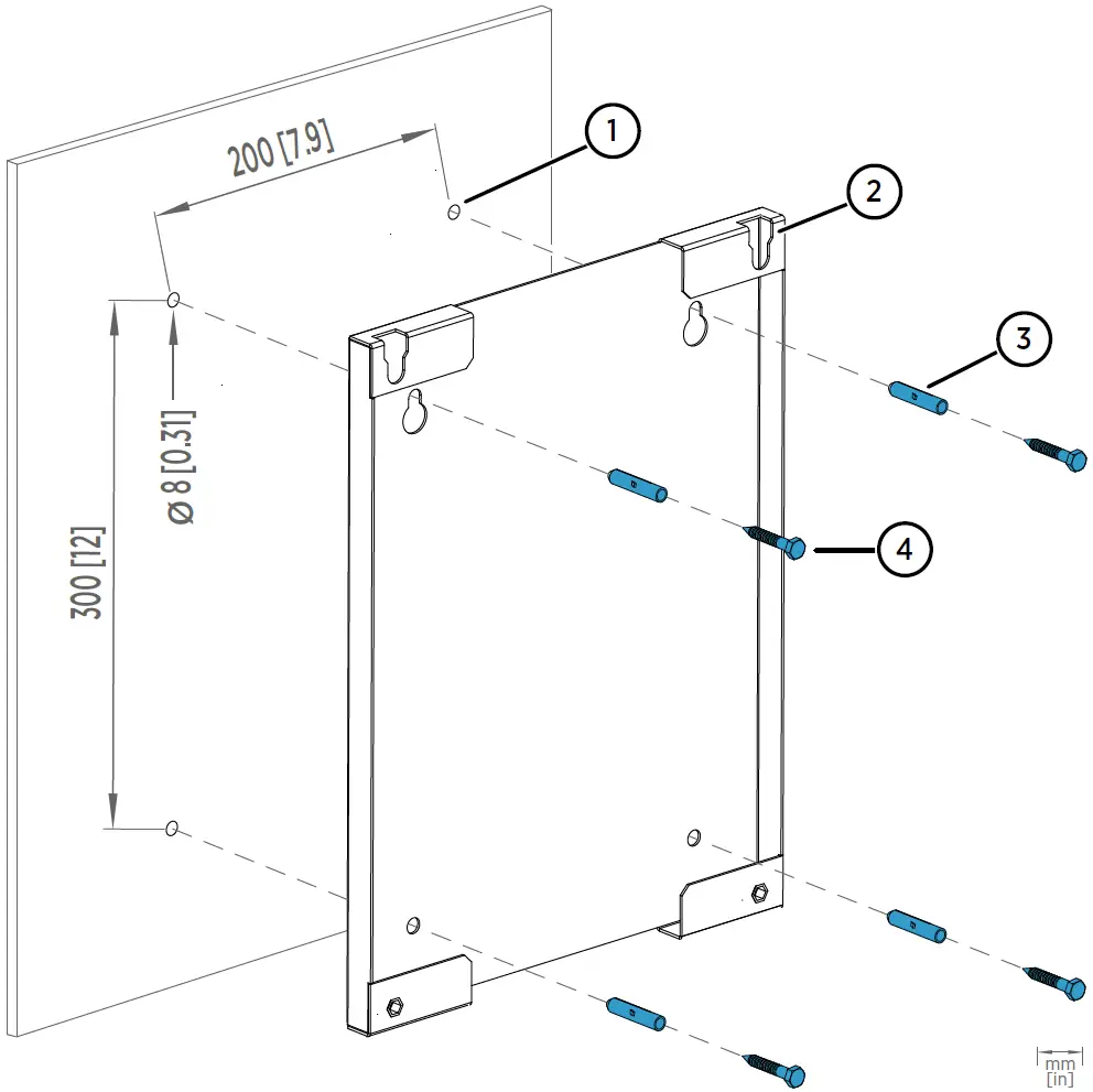
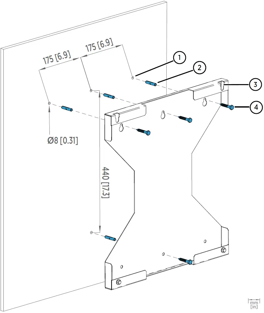
- Hole for wall plug (4 pcs)
- Mounting slot (2 pcs)
- Wall plug (4 pcs)
- Hex wood screw M6×40 DIN571 A2 (4 pcs)
- Drill holes into the wall. Use the mounting frame as a guide.
- Place the wall plugs into the drilled holes.
- Attach the mounting frame to the wall with screws.
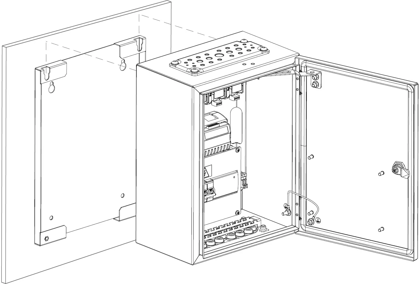
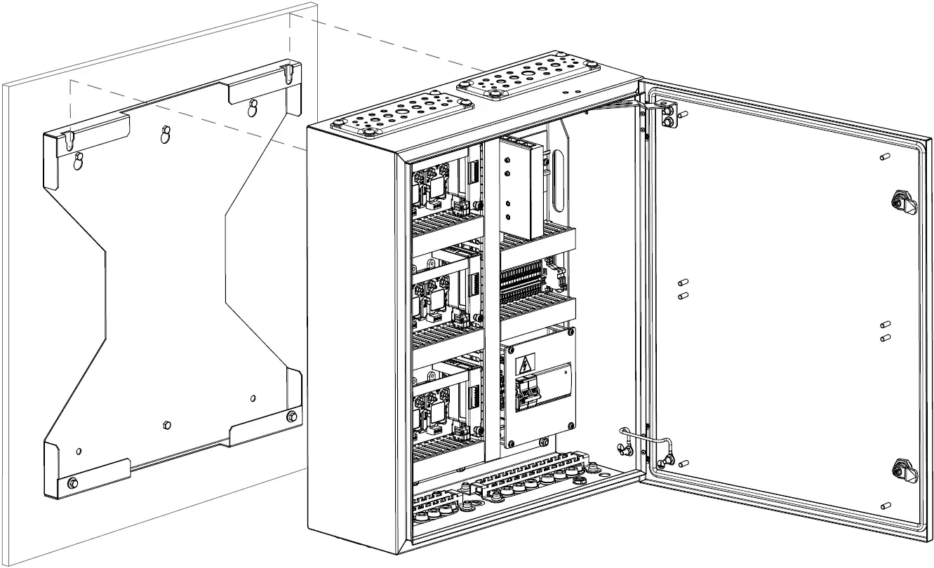
- Lift the enclosure into place.
Hang the enclosure onto the frame by sliding the mounting studs on the back of the enclosure into the mounting slots of the frame.
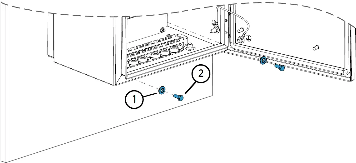
- Attach the bottom of the enclosure to the mounting frame.

- Washer with EPDM gasket 6.8/16×1.5/A2/EPDM (2 pcs)
- Hex screw M6×16 ISO7380 A4 (2 pcs)
Installing CAB100B with Mounting Frame
- Hole for wall plug (4 pcs)
- Wall plug (4 pcs)
- Mounting slot (2 pcs)
- Hex wood screw M6×40 DIN571 A2 (4 pcs)
- Drill holes into the wall. Use the mounting frame as a guide.
- Place the wall plugs into the drilled holes.
- Attach the mounting frame to the wall with screws.
- Lift the enclosure into place. Hang the enclosure onto the frame by sliding the mounting studs on the back of the enclosure into the mounting slots of the frame.

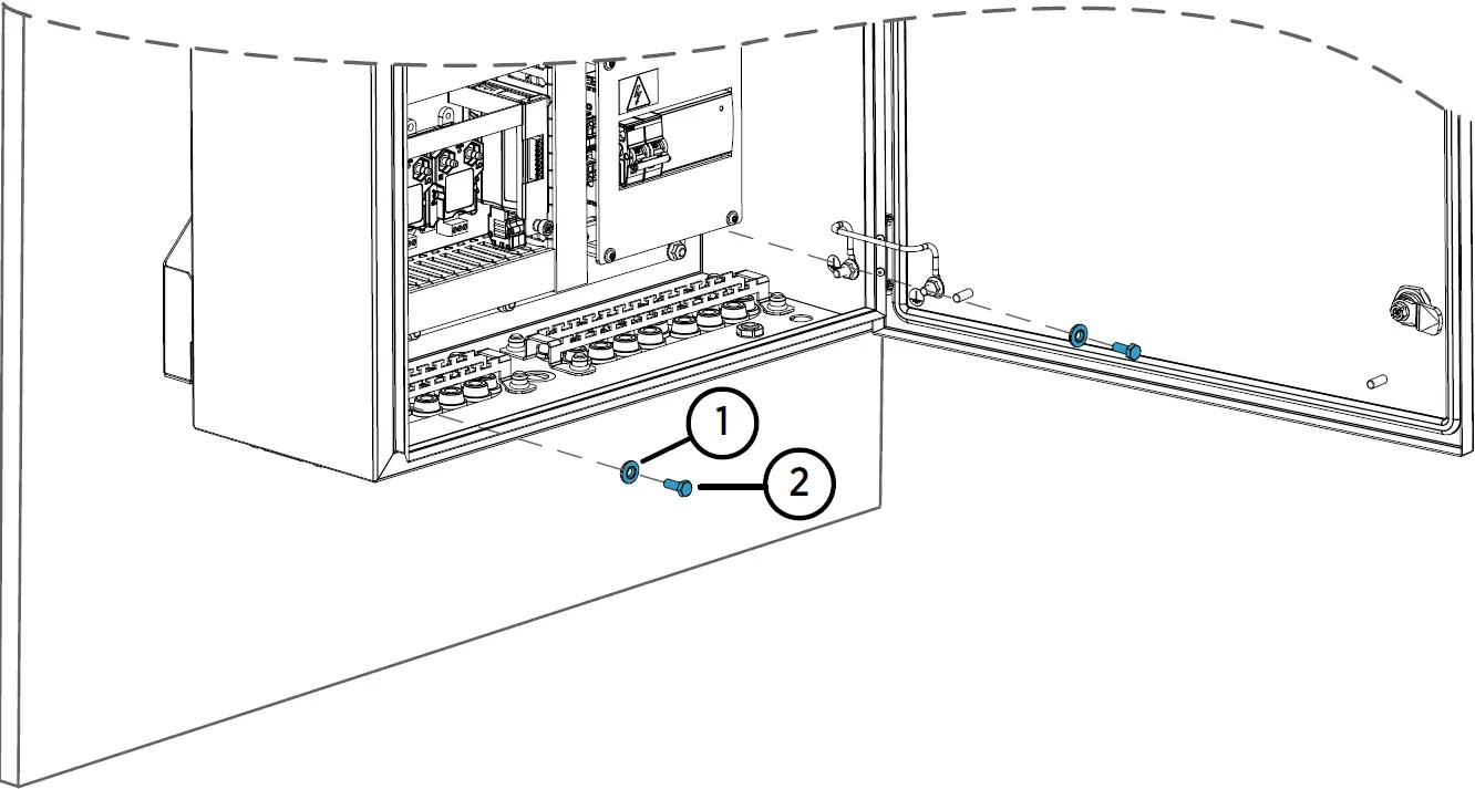
- Attach the bottom of the enclosure to the mounting frame.

- Washer with EPDM gasket 6.8/16—1.5/A2/EPDM (2 pcs)
- Hex screw M6—16 ISO7380 A4 (2 pcs)
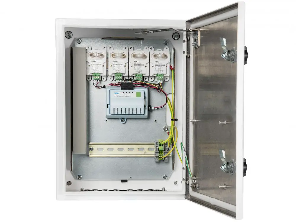
Physical Structure and Components
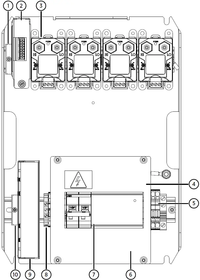
- Mounting clamp for DL4000 data logger
- DL4000 data logger
- PDT101 transmitters (4 pcs)
- Cover plate
- 24 V DC fuses T2.5A, 5 × 20 mm (2 pcs)
- 100 – 240V AC mains input and grounding point (under cover plate)
- Circuit breaker and power supply module
- Grounding terminal block
- Serial port server
- Mounting clamp for serial port server
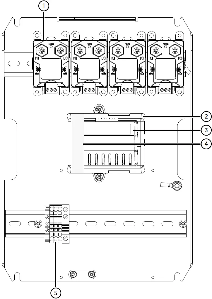
- PDT101 transmitters (4 pcs)
- vNet PoE data logger interface
- DL4000 data logger
- Protective label. Remove before installation.
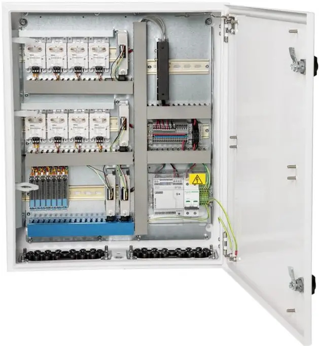
- Grounding terminal block
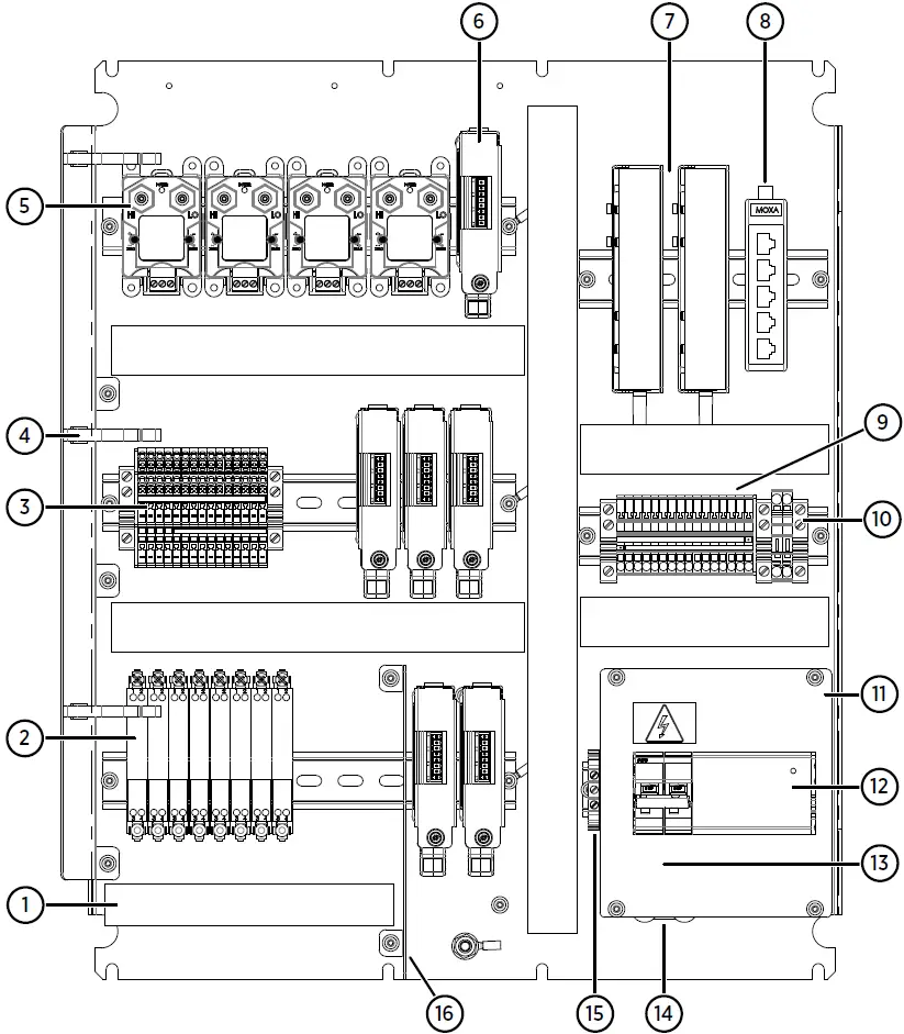
- Cable duct for intrinsically safe connections
- Safety barriers (8 pcs)
- Terminal block for analog input channels
- Holders for tubing (3 pcs)
- PDT101 transmitters (4 pcs)
- DL4000 data loggers (6 pcs)
- Serial port servers (2 pcs)
- Ethernet switch
- 24V DC power block
- 24V DC fuses T2.5A, 5-20 mm (2 pcs)
- Cover plate
- Circuit breaker and power supply module
- 100-240V AC mains input (under cover plate)
- Cable strain relief
- Grounding terminal block
- Partition plate separating intrinsically safe and non-intrinsically safe connections
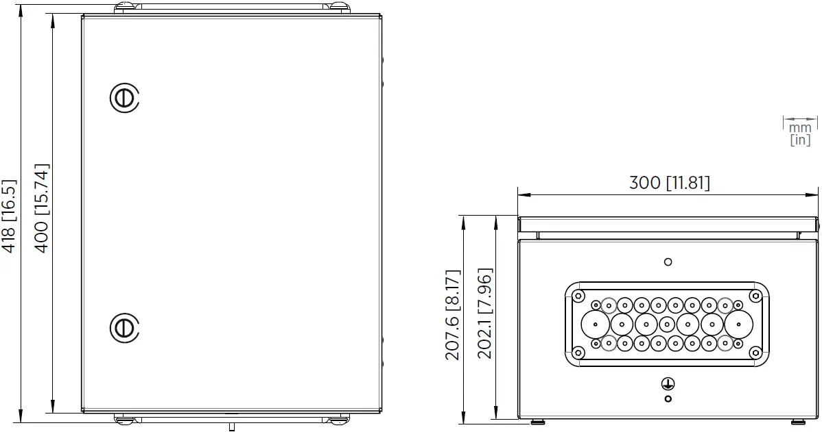
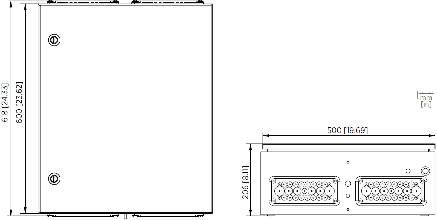
Enclosure Dimensions
CAB100A Enclosure Dimensions
CAB100B Enclosure Dimensions
Powering CAB100
Connecting AC (Mains) Power
- Screwdriver
- Wire cutters
- Wire-stripping pliers
For the AC (mains) power connection, you need an external disconnection device (for example, a detachable power cable or a mains power switch).
Note the following:
- The disconnection device must be rated 16 A or 20 A at 250 V AC, and must conform to any additional local regulations.
- The disconnection device must be visible from the cabinet, or lockable with a key to prevent accidental switching on during installation and maintenance.
- The cabinet must not block access to the disconnection device after it has been installed. The disconnection device must remain easy to operate.
The AC (mains) cable is not included in the delivery. Use an AC (mains) cable with a minimum cross-section of 3 × 0.75 mm² (18 AWG).
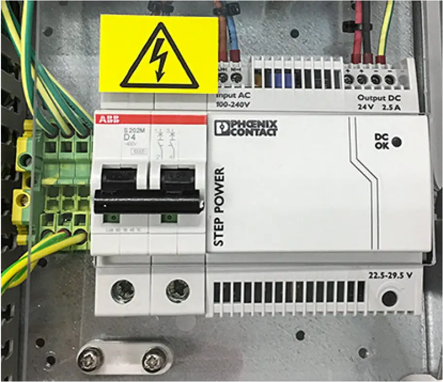
- Unscrew and remove the transparent cover plate protecting the circuit breaker and the power supply module.

- Lead the AC (mains) cable into the enclosure.
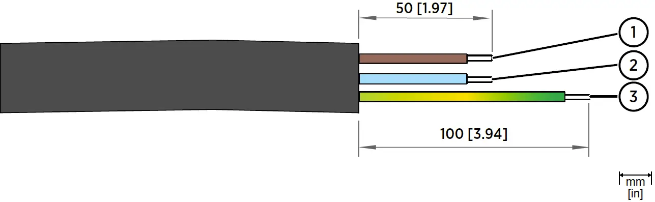
Lead the cable through a flange in the cabinet enclosure, following relevant safety regulations. Take note of safe areas around safety barriers or galvanic isolators inside the enclosure. - Strip approximately 100 mm (4 in) of the cable, and cut the phase and neutral wires to the length of approximately 50 mm (2 in). If you are using a stranded wire, add cable ferrules to the ends.

No.
Wire Wire color (International) Wire Color (North America) Min. Max. Wire Cross-Section
1
Phase L Brown Black Solid Wire:
0.75 … 4 mm2 (18 … 12 AWG)Stranded Wire:
0.75 … 2.5 mm2 (18 … 14 AWG)2
Neutral N Blue White
3
Grounding PE/GND Yellow/Green Green
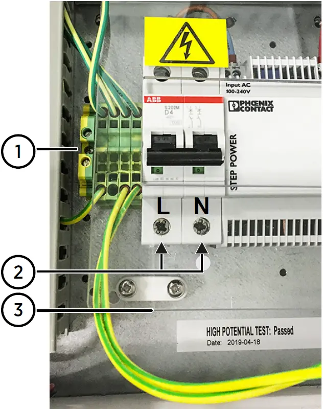
- Connect the phase, neutral, and grounding wires of the AC (mains) cable as indicated in the figure below.

- Connect the (green or yellow-green) grounding wire to the grounding terminal block.
- Connect the phase (L) and neutral (N) wires to the circuit breaker: the phase in the left-hand screw terminal and the neutral in the right-hand screw terminal.
- Mount the AC (mains) cable to the strain relief fixture located under the circuit breaker.
- Reattach the transparent cover plate.
- Switch on the circuit breaker.
- Switch on mains power.
Connecting Power Over Ethernet to CAB100A
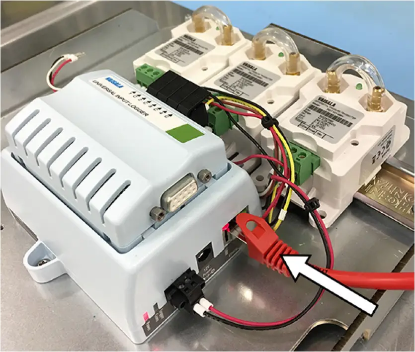
- In CAB100A PDT101 model with vNet PoE, power the cabinet by connecting your Ethernet PoE cable to the vNet device.

- Switch on mains power.
Maintenance and Calibration Services
Vaisala offers comprehensive customer care throughout the life cycle of our measurement instruments and systems. Our factory services are provided worldwide with fast deliveries. For more information, see www.vaisala.com/calibration.
- Vaisala Online Store at store.vaisala.com is available for most countries. You can browse the offering by product model and order the right accessories, spare parts, or maintenance and calibration services.
- To contact your local maintenance and calibration expert, see www.vaisala.com/contactus.
Warranty
For standard warranty terms and conditions, see www.vaisala.com/warranty.
Please observe that any such warranty may not be valid in case of damage due to normal wear and tear, exceptional operating conditions, negligent handling or installation, or unauthorized modifications. Please see the applicable supply contract or Conditions of Sale for details of the warranty for each product.
Technical Support
Contact Vaisala technical support at [email protected]. Provide at least the following supporting information as applicable:
- Product name, model, and serial number
- Software/Firmware version
- Name and location of the installation site
- Name and contact information of a technical person who can provide further information on the problem
For more information, see www.vaisala.com/support.
Recycling
- Recycle all applicable material.
- Follow the statutory regulations for disposing of the product and packaging.


