 Ps Tec PSM-NGT-G01 Autonomous Terminal
 Overview
 Overview
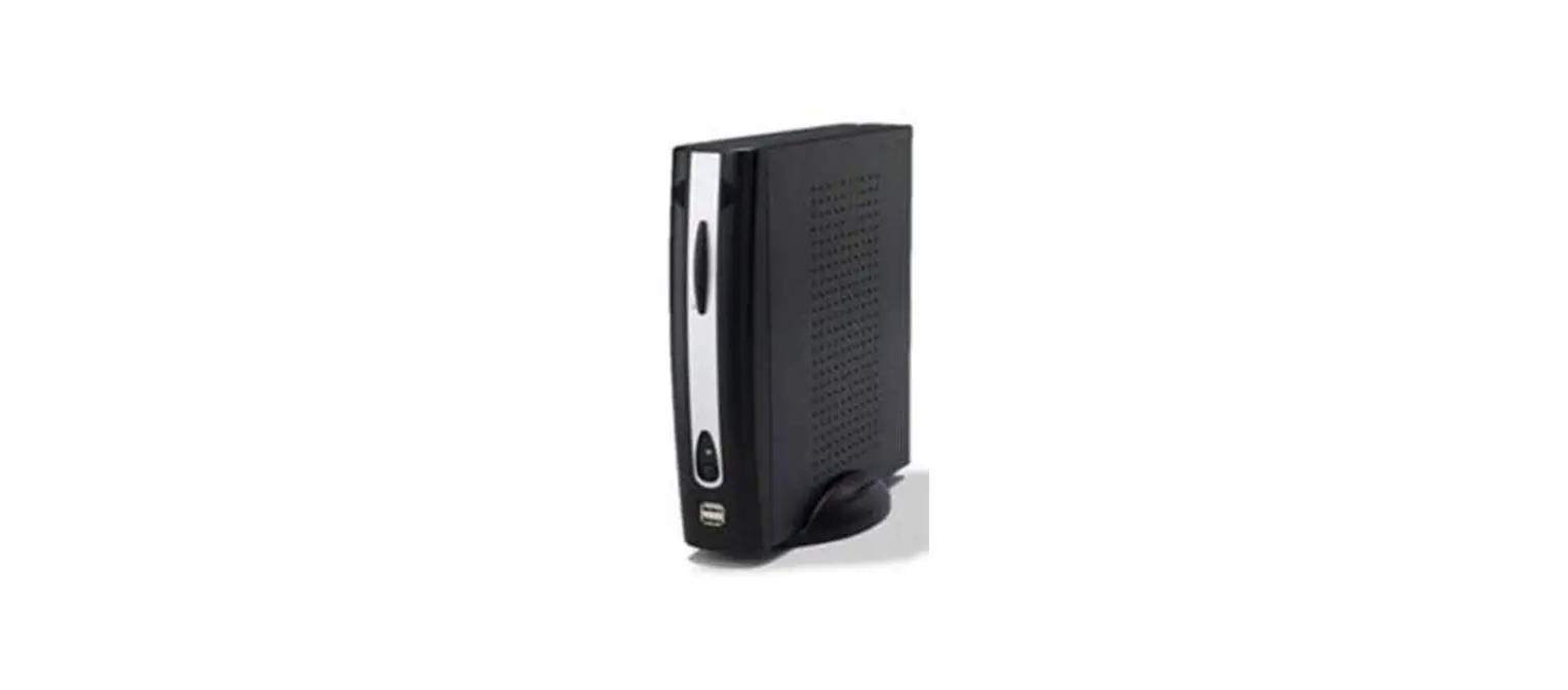
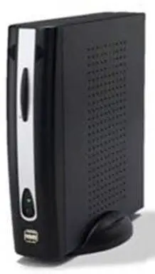
The terminal (PSM-NGT-G01) uses a 2.4GHz low-power wireless communication (IEEE 802.15.4 / BLE) module, WIFI module, and Ethernet chip in an ARM Coretex-A8 32bit processor environment, and wirelessly communicates with the counter ( products that measure production-related data). The terminal is installed in the same production facility as the counter, and the received data is transmitted to the management server using Ethernet or WIFI communication at regular intervals. When the counter requests data, the terminal transmits the data to the counter, and BLE communication is possible through a dedicated smartphone APP.
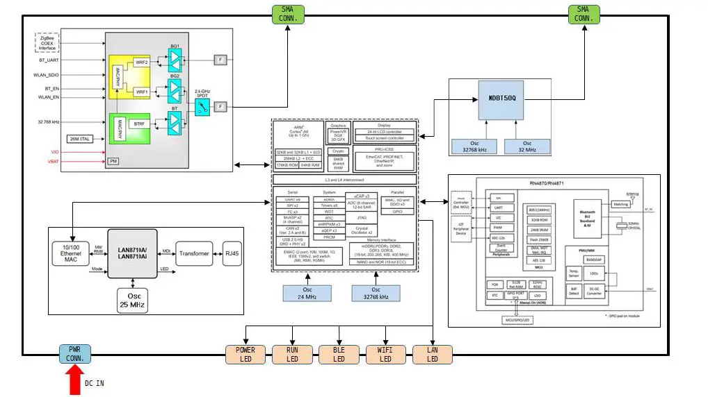
Module block diagram
- AP module (AM335X): It controls LAN chip, WIFI, BLE (MDBT50Q), BLE (RN4870) module and transmits and receives data.- It performs the designated function and displays the operation status on the LED.
- WIFI module (WL1835MOD): It is controlled by the AP module and transmits the data transmitted from the AP module to the server throughWIFI. – The data received through WIFI is transmitted to the AP module. – It uses 2.4G single-mode and external antenna
- BLE module (MDBT50Q): The data transmitted from the AP module is transmitted to the counter through BLE communication.- The data received through BLE communication is transmitted to the AP module.
- BLE (RN4870): The command requested by the smartphone app through BLE communication is transmitted to the AP module.- The result processed by the AP module is transmitted to the smartphone app through BLE communication
The internal block diagram of the terminal is as follows:
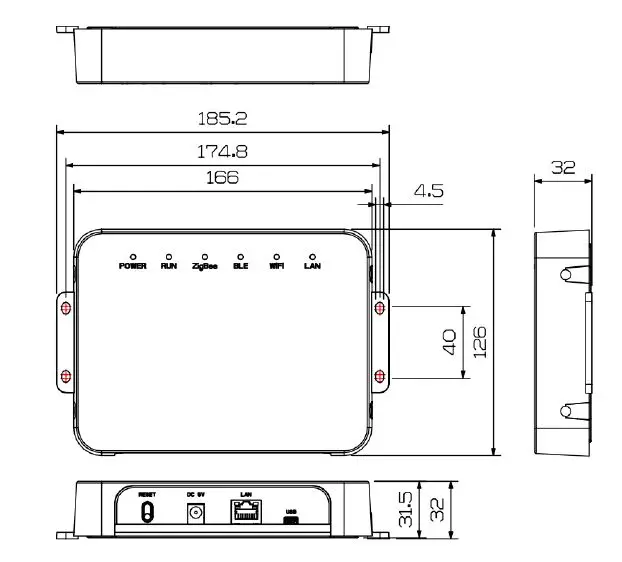
Appearance and name of each part
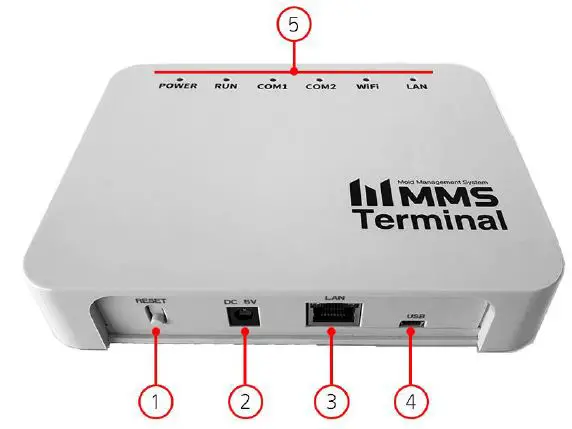
- RESET Button
- DC IN
- LAN Port
- Mini USB B type 5P
- LED (Power / Run / Comm.)
Size How to install
 How to install
- Positioning: For communication with the counter, select and install a place with less interference.
- Product installation
- Fix the 4 corners of the product with screws for equipment installation.
- Connect the 5V adapter power to the equipment.
Installation precautions: This device can only be installed by professional installers. This device should be installed in an installation location that can only be controlled by a professional installer, and an installation location is required. General users, in case of problems, contact a professional installer.
- Communication status check
- Check the Internet status by turning on the LAN / WIFI LED.
- Check the power status by turning on the Power LED.
- LED operation status
| Type | Color | Operation | LED Status |
| RUN | White | Booting | blinking quickly |
| RUN | White | In operation | blinking every second |
| LAN | green | Internet comm. | LED blinking |
| WIFI | yellow | Internet comm. | LED blinking |
| BLE | blue | BLE comm. | LED blinking |
| Power | red | Power on | LED always on |
Product Information
- Features and functions
- Receive counter information wirelessly.
- Send the received counter information to the server through the Internet
- Transfers the PRESET information registered in the server to the counter.
- Time synchronization of the counter
- Automatic update by connecting to server
- Command processing through the smartphone APP
- Administrator command mode support (Debug port)
- Hardware specification
- ARM Cortex-A8 1GHz Processor
- 4GB eMMC flash storage
- 512MB DDR3 RAM
- 2.4GHz Wireless BLE, WIFI
- Ethernet
Rating:
| Usable temperature | -25 ~ 80 ℃ | Warranty | 2 years (based on the date of manufacture) |
| Comm. cycle (Internet) | 10 minutes | DC power | 5V 3A |
QR code system (13 digits):
| Number of digits | 3 | 2 | 2 | 3 | 3 |
| Code | Model | Production year | Production week | Server code | Serial Number |
| Display | BTM | 20 | 01 | KARA | 001 |
| remarks | Terminal | The 2020 year | 01 week | – | number 1 |
Troubleshooting.
The status display and resolution are as follows.
| state | cause | resolution |
| When Power LED (red) is off | Power is not connected. | Power connection. |
| DC 5V adapter failure. | DC 5V adapter replacement | |
| When the RUN LED (white) blinks quickly | Booting process after connecting power. | Normal blinking after booting is complete |
| When the LAN LED (green) or WIFI LED (yellow) blink quickly. | No internet connection. | Internet connection |
| Internet configuration error | Check Internet configuration | |
| Server connection failure | Normal operation after connecting to server |
Precautions
- Injury may occur when installing the product, so wear protective equipment before work.
- A communication failure may occur in metal walls or enclosed environments that cause wireless interference. If communication failure continues to occur, check the cause of the failure and remove it.
- Please note that the service cannot be provided for damage caused by a non-standard environment, user carelessness, or arbitrary manipulation
FCC Information
This equipment has been tested and found to comply with the limits for a Class B digital device, pursuant to Part 15 of the FCC Rules. These limits are designed to provide reasonable protection against harmful interference in a residential installation. This equipment generates, uses, and can radiate radio frequency energy and, if not installed and used in accordance with the instructions, may cause harmful interference to radio communications. However, there is no guarantee that interference will not occur in a particular installation. If this equipment does cause harmful interference to radio or television reception, which can be determined by turning the equipment off and on, the
user is encouraged to try to correct the interference by one of the following measures:
- Reorient or relocate the receiving antenna.
- Increase the separation between the equipment and receiver.
- Connect the equipment into an outlet on a circuit different from that to which the receiver is connected.
- Consult the dealer or an experienced radio/TV technician for help.
Caution: Modifications not expressly approved by the party responsible for compliance could void the user’s authority to operate the equipment.
FCC Compliance Information: This device complies with Part 15 of the FCC Rules. Operation is subject to the following two conditions: (1) This device may not cause harmful interference, and (2) this device must accept any interference received, including interference that may cause undesired operation. This equipment complies with FCC RF radiation exposure limits set forth for an uncontrolled environment. This equipment should be installed and operated with a minimum distance of 20 centimeters between the radiator and your body. This transmitter must not be co-located or operating in conjunction with any other antenna or transmitter.


