


Quickstart
This is a
secure
Light Dimmer
for
.
To run this device please connect it to your mains power supply.
Important safety information
Please read this manual carefully. Failure to follow the recommendations in this manual may be dangerous or may violate the law.
The manufacturer, importer, distributor and seller shall not be liable for any loss or damage resulting from failure to comply with the instructions in this manual or any other material.
Use this equipment only for its intended purpose. Follow the disposal instructions.
Do not dispose of electronic equipment or batteries in a fire or near open heat sources.
What is Z-Wave?
Z-Wave is the international wireless protocol for communication in the Smart Home. This
device is suited for use in the region mentioned in the Quickstart section.

Z-Wave ensures a reliable communication by reconfirming every message (two-way
communication) and every mains powered node can act as a repeater for other nodes
(meshed network) in case the receiver is not in direct wireless range of the
transmitter.
This device and every other certified Z-Wave device can be used together with any other
certified Z-Wave device regardless of brand and origin as long as both are suited for the
same frequency range.
If a device supports secure communication it will communicate with other devices
secure as long as this device provides the same or a higher level of security.
Otherwise it will automatically turn into a lower level of security to maintain
backward compatibility.
For more information about Z-Wave technology, devices, white papers etc. please refer
to www.z-wave.info.
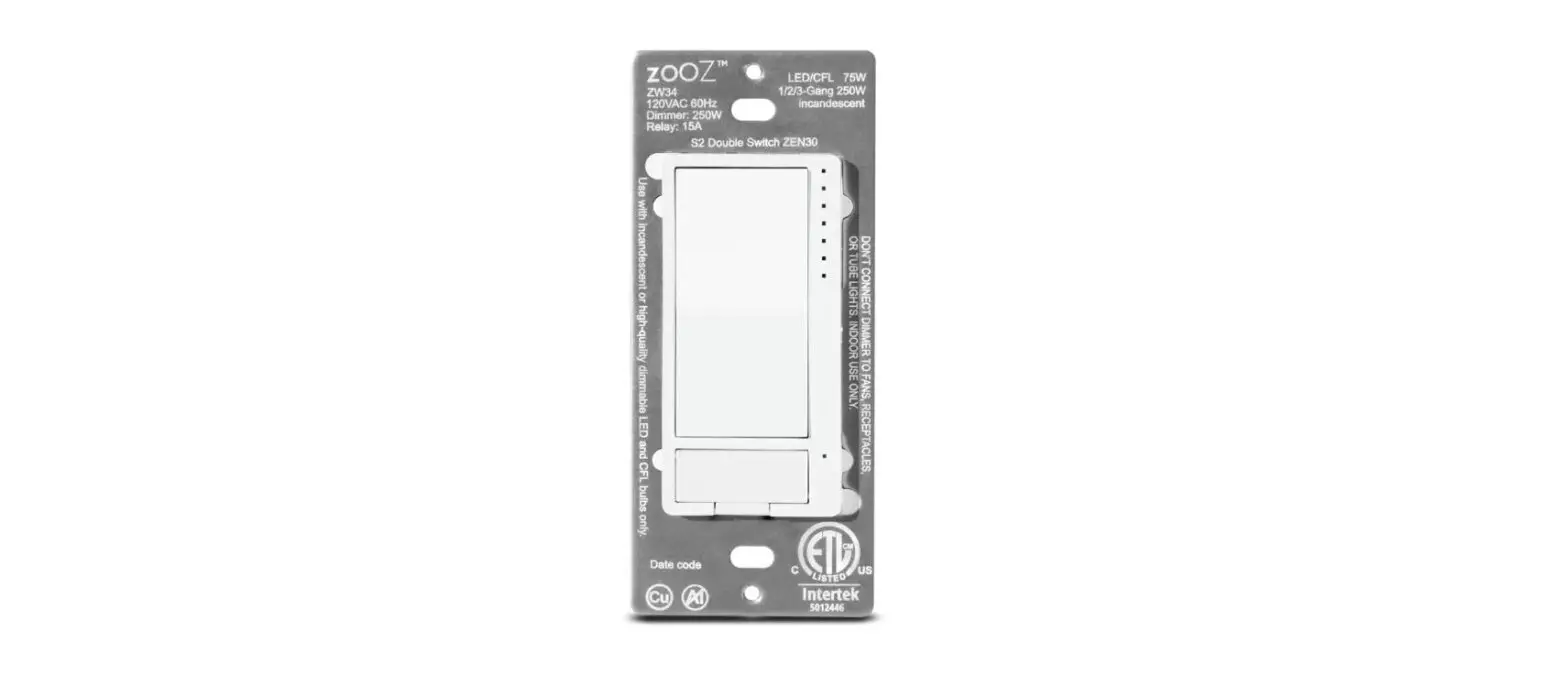
Product Description
PRODUCT FEATURES:- Manual or Z-Wave control of 2 separate loads (dimmer + relay)- Perfect replacement for a fan / light combo (neutral wire required)- Scene control for multi-tap scenarios on select hubs- Quick and easy pigtail wire installation (single pole only)- 4-color LED indicator and air-gap switch for added safety- Fully customizable dimming features including ramp rate, onbrightness level, and double tap to full brightness- Remembers and restores on/off status aer power failure- Built-in Z-Wave Plus signal repeater to extend network range- S2 security protocol and 500 Z-Wave chipSPECIFICATIONS:- Model Number: ZEN30- Z-Wave Signal Frequency: 908.42 MHz- Power: 120 VAC, 60 Hz- Dimmer Max Load: 75 W LED, 250 W incandescent; DONT use with tube lights, DC powered fixtures, or chandeliers- Relay Max Load: 15 A (1/2 HP)- Operating Temperature: 32-104 F (0-40 C)- Installation and Use: Indoor only
Prepare for Installation / Reset
Please read the user manual before installing the product.
In order to include (add) a Z-Wave device to a network it must be in factory default
state. Please make sure to reset the device into factory default. You can do this by
performing an Exclusion operation as described below in the manual. Every Z-Wave
controller is able to perform this operation however it is recommended to use the primary
controller of the previous network to make sure the very device is excluded properly
from this network.
Safety Warning for Mains Powered Devices
ATTENTION: only authorized technicians under consideration of the country-specific
installation guidelines/norms may do works with mains power. Prior to the assembly of
the product, the voltage network has to be switched off and ensured against re-switching.
Inclusion/Exclusion
On factory default the device does not belong to any Z-Wave network. The device needs
to be added to an existing wireless network to communicate with the devices of this network.
This process is called Inclusion.
Devices can also be removed from a network. This process is called Exclusion.
Both processes are initiated by the primary controller of the Z-Wave network. This
controller is turned into exclusion respective inclusion mode. Inclusion and Exclusion is
then performed doing a special manual action right on the device.
Quick trouble shooting
Here are a few hints for network installation if things dont work as expected.
- Make sure a device is in factory reset state before including. In doubt exclude before include.
- If inclusion still fails, check if both devices use the same frequency.
- Remove all dead devices from associations. Otherwise you will see severe delays.
- Never use sleeping battery devices without a central controller.
- Dont poll FLIRS devices.
- Make sure to have enough mains powered device to benefit from the meshing
Association – one device controls an other device
Z-Wave devices control other Z-Wave devices. The relationship between one device
controlling another device is called association. In order to control a different
device, the controlling device needs to maintain a list of devices that will receive
controlling commands. These lists are called association groups and they are always
related to certain events (e.g. button pressed, sensor triggers, …). In case
the event happens all devices stored in the respective association group will
receive the same wireless command wireless command, typically a ‘Basic Set’ Command.
Association Groups:
Group NumberMaximum NodesDescription
| 1 | 1 | The dimmer and relay will send basic_set reports to the hub when their status changes. |
| 2 | 5 | The dimmer supports Group 2 with up to 5 devices and willsend BASIC_SET report to other devices in Group 2 to communicate statuschanges. |
| 3 | 5 | The relay supports Group 3 with up to 5 devices and will send BASIC_SET report to other devices in Group 3 if its status changes. |
Configuration Parameters
Z-Wave products are supposed to work out of the box after inclusion, however
certain configuration can adapt the function better to user needs or unlock further
enhanced features.
IMPORTANT: Controllers may only allow configuring
signed values. In order to set values in the range 128 … 255 the value sent in
the application shall be the desired value minus 256. For example: To set a
parameter to 200 it may be needed to set a value of 200 minus 256 = minus 56.
In case of a two byte value the same logic applies: Values greater than 32768 may
needed to be given as negative values too.
Parameter 1: LED Indicator Mode for Dimmer
Choose if you want theLED indicator to turn on when theswitch (light) is on or off, or if youwant it to remain on or off at alltimes. This setting is for the top statusindicator only.
Size: 1 Byte, Default Value: 0
SettingDescription
| 0 | LED indicator is on when switch is off, LED indicator is off when switch is on (default); |
| 1 | LED indicator is on when switch is on, LED indicator is off when switch is off; |
| 2 | LED indicator is always OFF and LEDs dont indicate brightness level during dimming; |
| 3 | LED indicator is always ON. |
Parameter 10: Auto Turn-Off Timer for Relay
Use this parameter toset the time aer which you want therelay to automatically turn off once ithas been turned on. The numberentered as value corresponds to thenumber of minutes.
Size: 4 Byte, Default Value: 0
SettingDescription
| 0 | timer disabled |
| 1 – 65535 | minutes |
Parameter 11: Auto Turn-On Timer for Relay
Use this parameter toset the time aer which you want therelay to automatically turn on once ithas been turned off. The numberentered as value corresponds to thenumber of minutes.
Size: 4 Byte, Default Value: 0
SettingDescription
| 0 | timer disabled |
| 1 – 65535 | minutes |
Parameter 12: On Off Status Aer Power Failure
Set the on off status ofthe device aer power failure.
Size: 1 Byte, Default Value: 3
SettingDescription
| 0 | dimmer and relay forced to OFF (regardless of state prior to power outage); |
| 1 | dimmer forced to off, relay forced to on; |
| 2 | dimmer forced to on, relay forced to off; |
| 3 | remembers and restores on/off status for dimmer and relay aer power failure (default); |
| 4 | remembers and restores on/off status for dimmer, relay forced to on; |
| 5 | remembers and restores on/off status for dimmer, relay forced to off; |
| 6 | dimmer forced to on, remembers and restores on/off status for relay; |
| 7 | dimmer forced to off, remembers and restores on/off status for relay; |
| 8 | dimmer and relay forced to ON. |
Parameter 13: Ramp Rate Control for Dimmer
Adjust the ramp ratefor the dimmer (fade-in / fade-outeffect for on / off operation). Valuescorrespond to the number of secondsit take for the dimmer to reach fullbrightness or turn off when operatedmanually.
Size: 1 Byte, Default Value: 1
SettingDescription
| 0 | instant on/off; |
| 1 – 99 | seconds |
Parameter 14: Minimum Brightness
Set the minimumbrightness level (in %) for thedimmer. You wont be able to dimthe light below the set value.
Size: 1 Byte, Default Value: 1
SettingDescription
| 1 – 99 | % brightness |
Parameter 15: Maximum Brightness
Set the maximumbrightness level (in %) for thedimmer. You wont be able to addbrightness to the light beyond theset value. Note: if Parameter 17 is setto value 0, Parameter 15 isautomatically disabled.
Size: 1 Byte, Default Value: 99
SettingDescription
| 1 – 99 | % brightness |
Parameter 17: Double Tap Function for Dimmer
Choose if you want thedimmer to turn on to full brightnessor custom brightness level aer youdouble-tap the upper paddle.
Size: 1 Byte, Default Value: 0
SettingDescription
| 0 | the light will turn on to full brightness with double tap (default). |
| 1 | the light will turn on to the maximum brightness level set in Parameter 15 with double tap. |
Parameter 18: Double Tap Function for Dimmer: Disable/Enable
Enable or disable thedouble-tap function and assignbrightness level to single tap.
Size: 1 Byte, Default Value: 0
SettingDescription
| 0 | double tap to full / maximum brightness level enabled (default). |
| 1 | double tap to full / maximum brightness level disabled, single tap turns light on to last brightness level (or custom value set in Parameter 23) |
| 2 | double tap to full / maximum brightness level disabled, single tap turns light on to full brightness level. |
Parameter 19: Enable/Disable Load Control for Dimmer (Smart Bulb Setting)
Enable or disabledirect manual and Z-Wave control ofthe connected light. Works great forsmart bulb control. If disabled, thedimmer will no longer control theconnected bulb directly but will stillsend on/off and brightness reports tothe hub so you can use them tocreate automations for your smartbulbs or other switches. Scenes andother functionality will still beavailable through paddles.
Size: 1 Byte, Default Value: 1
SettingDescription
| 0 | manual control disabled. |
| 1 | manual control enabled |
| 2 | manual and Z-Wave control disabled. |
Parameter 2: LED Indicator Control for Relay
Choose if you want theLED indicator to turn on when therelay is on or off, or if you want it toremain on or off at all times
Size: 1 Byte, Default Value: 0
SettingDescription
| 0 | LED indicator is on when relay is off, LED indicator is off when relay is on (default); |
| 1 | LED indicator is on when relay is on, LED indicator is off when relay is off; |
| 2 | LED indicator is always OFF |
| 3 | LED indicator is always ON |
Parameter 20: Enable/Disable Load Control for Relay (Remote Control Setting)
Enable or disabledirect manual and Z-Wave control ofthe connected load. Works great forsmart bulbs or any type of remote /scene control. If disabled, the relaywill no longer control the connectedload directly but will still send on/off reports to the hub so you can usethem to create automations for yoursmart bulbs or other devices. Scenesand other functionality will still beavailable through the button.
Size: 1 Byte, Default Value: 1
SettingDescription
| 0 | manual control disabled. |
| 1 | manual control enabled |
| 2 | manual and Z-Wave control disabled. |
Parameter 21: Manual Dimming Speed
Choose how manyseconds it takes for the dimmer to gofrom 0% to 100% brightness whenpressing and holding the paddle.Increase the value to decrease thedimming speed.
Size: 1 Byte, Default Value: 4
SettingDescription
| 1 – 99 | seconds |
Parameter 22: Z-Wave Ramp Rate for Dimmer
Choose if you wouldlike to match the Z-Wave on/off ramprate with the manual ramp rate or setit separately in your hub.
Size: 1 Byte, Default Value: 0
SettingDescription
| 0 | Z-Wave on/off ramp rate matches the manual ramp rate set in Parameter 13. |
| 1 | Z-Wave on/off ramp rate is set separately through its command class in the hub. |
Parameter 23: Custom Brightness Level On for Dimmer
Set custom brightnesslevel (in %) for the dimmer to comeon to at single tap.
Size: 1 Byte, Default Value: 0
SettingDescription
| 0 | last brightness level |
| 1 – 99 | % brightness |
Parameter 3: LED Indicator Color for Dimmer
Choose the color of theLED indicators for the dimmer.
Size: 1 Byte, Default Value: 0
SettingDescription
| 0 | white |
| 1 | blue |
| 2 | green |
| 3 | red |
Parameter 4: LED Indicator Color for Relay
Choose the color of theLED indicator for the relay.
Size: 1 Byte, Default Value: 0
SettingDescription
| 0 | white |
| 1 | blue |
| 2 | green |
| 3 | red |
Parameter 5: LED Indicator Brightness for Dimmer
Choose the LEDindicators brightness level for thedimmer.
Size: 1 Byte, Default Value: 1
SettingDescription
| 0 | bright (100%) |
| 1 | medium (60%) |
| 2 | low (30%) |
Parameter 6: LED Indicator Brightness for Relay
Choose the LEDindicators brightness level for therelay.
Size: 1 Byte, Default Value: 1
SettingDescription
| 0 | bright (100%) |
| 1 | medium (60%) |
| 2 | low (30%) |
Parameter 7: LED Indicator Mode for Scene Control
Choose if you want theLED indicators next to the dimmerlight up when a scene is selected.Youll see 1 to 5 LEDs light up for 15tap triggers and 6 LEDs light up forthe press-and-hold trigger of anypaddle / button used.
Size: 1 Byte, Default Value: 1
SettingDescription
| 0 | LEDs enabled to indicate scene triggers; |
| 1 | LEDs disabled to indicate scene triggers (default). |
Parameter 8: Auto Turn-Off Timer for Dimmer
Use this parameter toset the time aer which you want the dimmer to automatically turn offonce it has been turned on. Thenumber entered as valuecorresponds to the number ofminutes.
Size: 4 Byte, Default Value: 0
SettingDescription
| 0 | timer disabled |
| 1 – 65535 | minutes |
Parameter 9: Auto Turn-On Timer for Dimmer
Use this parameter toset the time aer which you want thedimmer to automatically turn ononce it has been turned off. Thenumber entered as valuecorresponds to the number ofminutes.
Size: 4 Byte, Default Value: 0
SettingDescription
| 0 | timer disabled |
| 1 – 65535 | minutes |
Technical Data
| Hardware Platform | ZM5202 |
| Device Type | Light Dimmer Switch |
| Network Operation | Always On Slave |
| Firmware Version | HW: 2 FW: 1.00 |
| Z-Wave Version | 6.82.00 |
| Certification ID | ZC10-20026859 |
| Z-Wave Product Id | 0x027A.0xa000.0xa008 |
| Neutral Wire Required | ok |
| Z-Wave Scene Type | Central Scene |
| Electric Load Type | Dimmable ELV (Magnetic)Dimmable LEDDimmable MLV (Magnetic)IncandescentInductive (e.g. Motor)LEDMLV (Magnetic) |
| Firmware Updatable | Updatable by Consumer by RF |
| Color | White |
| Loads Controlled | 2 |
| Security V2 | S2_UNAUTHENTICATED |
| Frequency | XXfrequency |
| Maximum transmission power | XXantenna |
Supported Command Classes
- Association Grp Info
- Association V2
- Basic V2
- Central Scene V3
- Configuration
- Device Reset Locally
- Firmware Update Md V4
- Manufacturer Specific V2
- Multi Channel Association V3
- Multi Channel V4
- Powerlevel
- Security 2
- Supervision
- Switch Binary
- Switch Multilevel V4
- Transport Service V2
- Version V3
- Zwaveplus Info V2
Controlled Command Classes
- Basic V2
Explanation of Z-Wave specific terms
- Controller — is a Z-Wave device with capabilities to manage the network.
Controllers are typically Gateways,Remote Controls or battery operated wall controllers. - Slave — is a Z-Wave device without capabilities to manage the network.
Slaves can be sensors, actuators and even remote controls. - Primary Controller — is the central organizer of the network. It must be
a controller. There can be only one primary controller in a Z-Wave network. - Inclusion — is the process of adding new Z-Wave devices into a network.
- Exclusion — is the process of removing Z-Wave devices from the network.
- Association — is a control relationship between a controlling device and
a controlled device. - Wakeup Notification — is a special wireless message issued by a Z-Wave
device to announces that is able to communicate. - Node Information Frame — is a special wireless message issued by a
Z-Wave device to announce its capabilities and functions.


