![]()
 Carbon Monoxide Detector-Transmitter
E2638-CO
User Manual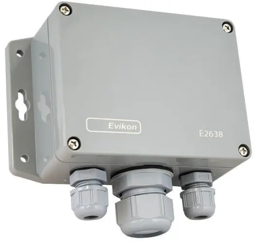
Carbon Monoxide
Carbon Monoxide is a colorless, odorless, and tasteless gas that is highly toxic.
Synonyms: Carbonous oxide, Carbon (II) oxide, Flue gas, Monoxide.
| Chemical formula | CO | |
| Molar weight | 28 | |
| Relative gas density (to air) | 0.97 | |
| Conversion | 1 ppm = 1.15 mg/m3 | |
| Boiling point | -191 .5 °C | |
| Low explosive limit (LEL), % vol. in air | 13. | |
| Upper explosive limit (UEL), % vol. in air | 74 | |
| Odor | Odorless | |
| Hazards | Highly toxic. Mild poisoning causes lightheadedness, confusion, headache, dizziness, and flu-like effects. Larger exposures can lead to toxicity of the CNS and heart, and death. After acute poisoning, long-term problems may occur. CO also has negative effects on a baby if exposed during pregnancy. Chronic exposure to low levels can lead to depression, confusion, and memory loss. | |
| Exposure limits (NIOSH) | TWA | 40 mg/m3 /35 ppm |
| IDLH | 1380 mg/m3 /1200 ppm | |
Conversion of ppm to mg/m³ is calculated for 25°C and 1 atm.
Specifications
| Sensor type | Electrochemical cell | |
| Sampling method | Diffusion | |
| Detection range | 0…300 ppm | I 0…1000 ppm |
| Maximum overload | 2000 ppm | |
| Resolution / digital unit | 1 ppm | |
| Response time T90 | < 30 s | |
| Sensor lifetime | > 10 years | |
| Calibration interval | 12 months | |
| Repeatability | < t 5% | |
| Signal update | Every 1 second | |
| Power supply | 12…36 12…36 VDC (default), or 230 VAC as options | |
| Power consumption | < 2 VA | |
| Analog outputs | 2 x 4-20 mA / 0-10 V, user settable | |
| Load resistance | Fk< (Us- 2V)/ 22 mA for 4-20 mA R. > 250 kOhm for 0-10 V mode: | |
| Digital interface | RS485, Modbus RTU protocol; No galvanic isolation | |
| Enclosure | Grey ABS, wall mount, protection class IP65 | |
| Dimensions | H90 x W145 x D55 mm (overall dimensions H140 x W145 x D55 mm) | |
| CE marking | According to 2014/30/EU and 2014/35/EU, EN 50491-41:2012 EN 61000-6-3:2020, EN 61326-1:2013(EMC, emissions) EN 61000-6-1:2019, EN 61000-6-2:2019(EMC, Immunity) EN 60079-29-1:2016, EN 60079-29-2:2015 and EN 60079-29-3:201 4 | |
| Outputs assignment | OUT1 gas; OUT2 gasNOTE for LCD version only output 1 is available | |
| Output scale width | > 10 x resolution Recommended: 20-100% of the detection range | |
| Operating conditions | -20…+50 °C, 0…90% RH non-condensing, 0,9…1,1 atm Explosion-safe areas, Non-aggressive atmosphere NOTEI The sensor exhibits considerable sensitivity to acetylene, ethylene, hydrogen and nitric oxide | |
| Relay option | |
| Output relays | 2 x SPST relays (closing contact), 250 VAC/ 30 VDC, 5A max |
| Default alarm set-points | RE1 (LOW): set 25; release 20 ppm RE2 (HIGH): set 35; release 28 ppm |
| Signalling options | |
| Visual | Red and green LEDs |
| Acoustic alarm | Buzzer 85 dB |
| LCD indicator option | |
| Operating temperature | 0…+50 °C |
| Display dimensions | 72 x 36 mm |
| Number of digits | 3.5 7-segment |
| Character height | 14mm |
| Other features | Backlight |
| Other options | |
| Remote probe | Protection IP65, default cable length 3.0 m; max height 80 mm, max diameter 65 mm |
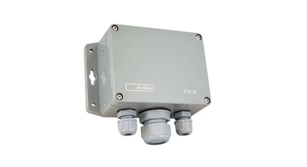
Product description
E2638 series detectors-transmitters belong to the PluraSens® family of multifunctional measurement instruments. The instruments utilize gas sensors of various types with excellent repeatability, stability, and long lifetime.
E2638 series provides two independent analog outputs OUT1 and OUT2, user-selectable to 4-20 mA or 0-10 V, proportional to gas concentrations. RS485 Modbus RTU digital communication interface allows easy instrument configuration and integration into various automation systems.
The following features are available as an option:
- Two relays RE1 and RE2 with closing contacts. Relay outputs can be used to switch alarm sirens, ventilation fans, shut-off valves, or other actuators,
- Acoustic (85 dB buzzer) and visual (red and green LED) signaling,
- 24 VAC or 230 VAC as options for power supply module,
- LCD indicator,
- Remote probe.
The version of your device is marked on the package. If the symbol ⚠ is marked on the equipment, consult the documentation for further information.
Safety requirements
Misuse will impair the protection of the product. Always adhere to the safety provisions applicable in the country of use.
Do not perform any maintenance operation with the power on. Do not let water or foreign objects inside the device.
Removal of the PCB from the enclosure voids the warranty. Do not touch the electronic components directly, as they are sensitive to static electricity.
Connection diagrams can be found in the electrical connections section. The device might not perform correctly or be damaged if the wrong power supply is connected.
External circuits connected to the equipment should have sufficient insulation rating according to the environmental conditions and equipment power.
A disconnecting device that is marked as such and easily accessible should be included in the installation of this product.
Operating conditions
The device should be used both in a non-hazardous area and in a basic electromagnetic environment, where the latter is defined in EN 61326-1. Avoid strong mechanical shock and vibrations. Avoid corrosive atmosphere and areas highly contaminated with dust, oil mist, etc. Keep the instrument away from direct sunlight. A sudden temperature or humidity change might affect the sensitivity of the sensor.
Installation guidelines
Before proceeding with the installation it is mandatory to read the Safety requirements section and make sure to comply with all listed instructions. Installation standards EN
60079-29-2 and EN 45544-4 are also recommended for further instructions and related information about the installation. During the installation of the detector-transmitter the following points must be considered:
- Application (air quality control or leakage detection)
- Properties of the space under investigation (room geometry, direction, and velocity of airflows, etc.),
- Carbon monoxide has practically the same density as air and spreads evenly in the room. Install the sensor in proximity to possible leakage or generation source, taking into consideration the temperature of the gas, the air currents in the room, etc.
- The device should be accessible for maintenance and repair.
The aforementioned conditions above will affect the coverage area of the device. however, the coverage area for a transmitter is usually between 2.5 to 5 meters radius.
For early leakage detection install the sensor as close as possible to the potential leakage sources (flanges, valves, pressure reducers, pumps, etc.), taking into consideration other points listed above.
For general area monitoring without definite leakage sources, the detectors should be distributed evenly in the room.
For personal safety control, the detectors are installed in the breathing zone (at the height of the head of people or animals). The recommended sensor position is vertical, pointing downwards.
For installing the device, attach the device to the wall using provided screws through the side mounting holes or key slots (see mountains dimensions).
Mounting dimensions
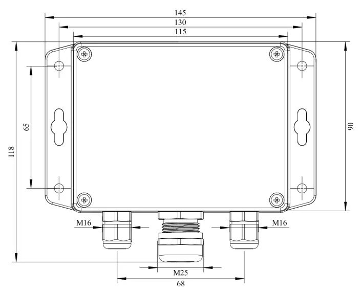 Front view
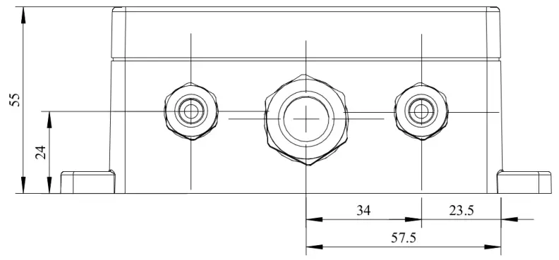 Bottom view
Sensor probe handling
The E2638 series devices are available with a remote probe. The remote probe is connected to the main unit with a shielded cable. The default remote probe cable length is 3 m.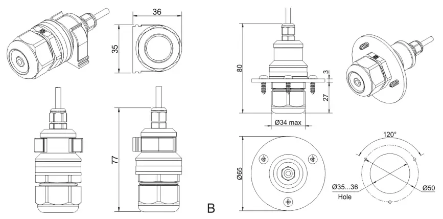
A )Wall mount remote probe with fixing clamp (default version) ,
B) Remote probe with rubber flange and three self-tapping screws (on request)
The sensor probes of all types are equipped with a hydrophobic microporous PTFE filter to protect the sensor from dust, dirt, and water drops. The filter should be replaced if it gets strongly contaminated. To replace the PTFE filter, unscrew sensor head cap and remove the old filter. Place a new filter into the cap and tighten it again.
NOTE! Never stab or press the filter near its center where the sensor is located since this may damage the sensor. Do not remove the filter as it may cause the device to show incorrect values and/or break the sensor.
The recommended orientation of the sensor probe is vertical with the sensor tip pointing downwards. This prevents the possible accumulation of condensed water on the sensor protection filter.
Gas sensor replacement procedures
- Remove the sensor head cap from the device (or the remote probe),
- Remove the PTFE filter (if it is not removed within the cap),
- Remove the O-ring rubber,
- Detach the electrochemical sensor from the device,
- Insert the new electrochemical sensor inside,
- Put back the O-ring rubber, PTFE filter, and the head cap, respectively.
Electrical connections
Unscrew four lid screws and detach the lid from the device. Use two M16 cable glands to let in the cables of the power supply and of the external devices. Without turning on the power, plug the power cable, and connect the analog/relay outputs and/or digital interface terminals to the necessary devices according to the relevant connection diagram.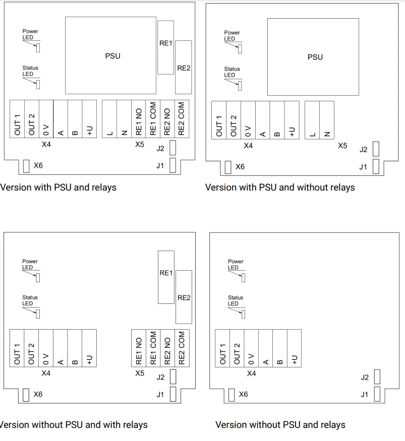
| Jumpers | |
| J1 | OUT1 type (open: 4-20 mA; closed 0-10 V) |
| J2 | OUT2 type (open: 4-20 mA; closed 0-10 V) |
| X6 | Reset Modbus network parameters to default |
| X4 terminals | |
| OUT1 | 4-20 mA / 0-10 V output |
| OUT2 | 4-20 mA / 0-10 V output |
| OV | 0 V / 24 VAC Neutral (optional) |
| A | RS485 A / Data + |
| B | RS485 B / Data – |
| +U | +24 VDC / 24 VAC Phase (optional) |
| X5 terminals (optional) | |
| L | 90.. 265 VAC Phase |
| N | 90…265 VAC Neutral |
| RE1 NO | Relay 1, normally open terminal |
| RE1 COM | Relay 1, common terminal |
| RE2 NO | Relay 2, normally open terminal |
| RE2 COM | Relay 2, common terminal |
The screwless quick connect spring terminals on the E2638 series devices are suitable for a wide range of wires with a cross-section of 0.2…1.5 mm2. We recommend striping the wire end by 8…9 mm and using wire end sleeves.
To connect the wire, insert the wire end into the terminal hole. To disconnect, push the spring-loaded terminal lever, pull the wire out, and release the lever.
Use a twisted-pair cable, e.g. LiYY TP 2×2×0.5 mm2 or CAT 5, to connect the device to the RS485 network. A and B on the device represent DATA+ and DATA- respectively, polarity must be respected when connecting to an external RS485 network.
Both analog outputs can be independently changed between 4-20 mA and 0-10 V type using jumpers J1 (OUT1) and J2 (OUT2). By closing pins on a specific jumper the related output is 0-10 V, with an open jumper the output is 4-20 mA. Power restart is required after changing the position of the jumpers.
NOTE! The outputs are not galvanically isolated from the external power supply and share a common 0V. Allowed load resistance limits are stated in the Specifications table. To power the instrument from an external power source, connect terminals 0V and +U to the source.
If the integrated mains power supply module is used, connect terminals L and N to the mains.
NOTE! Actuator short-circuits should be avoided, to protect the instrument relays, use external fuses or safety switches.
Correct and incorrect cabling for 24 VAC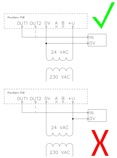
Operation
Turn on the power. The instrument warm-up time takes about 1 minute after switching on and the final sensor stabilization time to maximum accuracy takes about 30 minutes. The operating status is indicated by the LED on the PCB of the device. The control LED (red) response to different processes is presented in the following table:
| Mode | LED mode |
| During calibration mode or sensor heating period (if activated) | 0.5 Hz (50% on, 50% off) |
| Relay 1 turned on | Blinking 1 Hz (50% on, 50% off) |
| Relay 2 turned on | Blinking 2 Hz (50% on, 50% off) |
| During Modbus communication cycle | Short on-off pulses |
| Normal operating/measurement | Continuously on or off |
Make sure that the detector-transmitter is properly mounted, the external devices connected, power LED (green) on and control LED (red) constantly lit. Place the lid back and fix it with the screws. The device is ready to use.
Maintenance
Do not perform any maintenance operation with the power on.
Clean the device with a soft damp cloth. Do not use any abrasive cleaning agents. Do not immerse the device in water or any cleaning media.
Calibration
E2638-CO gas detector-transmitters have been calibrated by the Manufacturer with standard gas mixtures before delivery. Provided that the sensor is used under moderate conditions, the recommended interval for field recalibration is 12 months. Please contact your dealer for more information.
Delivery set
- Detector-transmitter E2638
- Mounting accessories:
- 4 screws with plastic dowels
- Fixing clamp for remote probe version

Order code for E2638-CO options
| E2638 options | Order code |
| Remote probe, 3 m cable | E2638-CO-RP33-3 |
| Remote probe, 10 m cable | E2638-CO-RP33-10 |
| Duct mount option, stem 035xL230 mm | E2638-CO-DM |
| Integrated 24 VAC power supply module | E2638-00-24VAC |
| Integrated 90…265 V mains power supply module | E2638-00-230 |
| Local LCD single value display 36 mm x 72 mm | E2638-CO-LCD |
| Remote LCD single value display, wall mount box 115 x 65 x 40mm, 3 m cable | E2638-CO-RLCD3 |
| Two SPST relays | E2638-CO-R |
| Two LEDs (visual alarm) | E2638-CO-LED |
| Buzzer (acoustic alarm) | E2638-CO-B |
| Self-test button for relays | E2638-CO-TB |
| Integrated coreless micropump | E2638-CO-MP |
Configuring
A standard configuration kit includes a USB-RS485 converter, fixed flow regulator, gas tubing with applicators, and a software pack. Please contact your Seller for more information.
Detectors-transmitters E2638 share all functionalities of the PluraSens® multifunctional platform. The features and options include:
- Digital output change rate-limiting filter
- Digital integrating (averaging) filter
- Free assignment of each analog output to the chosen parameter
- Flexible setting of analog output scales for each output
- Output zero and slope adjustment for calibration
- Free assignment of each of two relays to the chosen parameter
- Several relay control logic modes
- Switch delays and minimum on/off state durations for each relay
The output scales can be changed by Modbus commands by using the configuration software and the standard configuration kit (see Modbus RTU Communication).
Return to default settings
To reset the device’s Slave ID, baud rate, and stop bit numbers to factory settings, proceed as follows:
- De-energize the device
- Connect the X6 jumper
- Turn on the device
- De-energize the device
- Disconnect the X6 jumper
- Turn on the device
Modbus RTU Communication
RS485 communication interface
| Databits: 8 Parity: none / odd / even Stop bits: 1 or 2 Protocol: Modbus RTU | Supported Modbus functions: 03 – Read multiple registers 06 – Write a single register |
Communication parameters
| Parameter | Permitted values | Default |
| Supported baud rates | 1200, 2400, 4800, 9600, 19200, 38400, 57600 | 9600 |
| Data bits | 8 | 8 |
| Parity | none / odd / even | none |
| Stop bits | 1, 2 | 1 |
| Protocol | Modbus RTU | |
| Modbus functions | 03 – Read multiple registers 06 – Write a single register | |
| Error codes | 01 – Illegal function 02 – Illegal data address 03 – Illegal data value 04 – Slave device failure (details of last error 04 can be read from register 0x0008) | |
Modbus holding registers
Register addresses are shown 0-based, Address in hexadecimal, Reg in decimal format.
Modbus holding register numbers MHR are shown in the decimal 1-based format and may be addressed either from 00001 or 40001 base.
| Address | Reg / MHR | RW | Description | Supported values (dec) | Default |
| 0x0001 | 1 / 40002 | R | Hardware version | – | |
| 0x0002 | 2 / 40003 | R | Software version | – | |
| 0x0003 | 3 / 40004 | R | Product serial number | 1…65535 | – |
| 0x0004 | 4 / 40005 | RW | Slave ID (net address) * | 1…247 ** | 1 |
| 0x0005 | 5 / 40006 | RW | Baud rate * | 1200, 2400, 4800, 9600, 19200, 38400, 57600 | 9600 |
| 0x0006 | 6 / 40007 | RW | Response delay, ms | 1…255 | 10 |
| 0x0007 | 7 / 40008 | RW | Stop bits, parity bit * | 1 – No parity bit, 1 stop bit (default after factory reset) 2 – No parity bit, 2 stop bits 3 – Odd parity, 1 stop bit 4 – Even parity, 1 stop bit NOTE: 3 and 4 are available starting from the Software version 0x218 (dec. 536) |
1 |
| 0x0008 | 8 /40009 | R | Last error code | 1…255 | – |
| 0x0011 | 17 / 40018 | RW | Technological: age of last data in seconds (read) / restart (write) | 0…65535 s (read), writing 42330 restarts the instrument | – |
| 0x00A5 | 165 /40166 | RW | Zero adjustments for gas data, ADC | -32000…+32000 ADC units | 0 |
| 0x00A6 | 166 /40167 | RW | Slope adjustment for gas data | 1…65535 | 512 |
| 0x00A7 | 167 /40168 | RW | Change rate limit for gas units/ s | 1…32000, 0 – no limit | 0 |
| 0x00A8 | 168 / 40169 | RW | Integrating filter time constant, s | 1…32000 (seconds), 0 – no filter | 0 |
| Address | Reg / MHR | RW | Description | Supported values (dec) | Default |
| 0x00C9 | 201 /40202 | RW | Parameter tied to analog output 1 | 0 – None 2 – Gas concentration 9 – Forced Modbus control, value set in MHR / 40204 | 2 |
| 0x00CA | 202 /40203 | RW | Parameter tied to analog output 2 | 0 – None 2 – Gas concentration 9 – Forced Modbus control, value set in MHR / 40205 | 2 |
| 0x00CB | 203 /40204 | RW | Forced value for analog output 1*** | 0…1000 (0.0%. 100.0% of output scale) | 0 |
| 0x00CC | 204 /40205 | RW | Forced value for analog output 2*** | 0…1000 (0.0%. 100.0% of output scale) | 0 |
| 0x00D3 | 211 /40212 | RW | Parameter tied to relay RE1 | 0 –none 2 – gas concentration 9 – control by Modbus control, state set in MHR / 40214 | 2 |
| 0x00D4 | 212 /40213 | RW | Parameter tied to relay RE2 | 0 – none 2 – gas concentration 9- – control by Modbus control, state set in MHR / 40215 | 2 |
| 0x00D5 | 213 /40214 | RW | Forced state for relay RE1*** | 0 –off, 1 – on | 0 |
| 0x00D6 | 214/ 40215 | RW | Forced state for relay RE2*** | 0 – off, 1 – on | 0 |
| 0x00D7 | 215 /40216 | RW | Switching delay for relay RE1 | 0…1000 (s) | 0 |
| 0x00D8 | 216 /40217 | RW | Switching delay for relay RE2 | 0…1000 (s) | 0 |
| 0x00D9 | 217 /40218 | RW | Minimal on/off time for relay RE1 | 0…1000 (s) | 0 |
| 0x00DA | 218 /40219 | RW | Minimal on/off time for relay RE2 | 0…1000 (s) | 0 |
| Address | Reg / MHR | RW | Description | Supported values (dec) | Default |
| 0x00DB | 219 /40220 | RW | Control logic for relay RE1 | 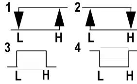 0 – none 0 – none1 – relay on at high values 2 – relay on at low values 3 – relay on at values within the range 4 – relay on for the values out of the range | 0 |
| 0x00DC | 220 /40221 | RW | Control logic for relay RE2 | 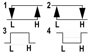 0 – none 0 – none1 – relay on at high values 2 – relay on at low values 3 – relay on at values within the range 4 – relay on for the values out of the range | 0 |
| 0x00DD | 221 /40222 | RW | LOW setpoint for relay RE1 | 0…65535 (gas units) | see Specifications |
| 0x00DE | 222 /40223 | RW | HIGH setpoint for relay RE1 | 0…65535 (gas units) | see Specifications |
| 0x00DF | 223 /40224 | RW | LOW setpoint for relay RE2 | 0…65535 (gas units) | see Specifications |
| 0x00E0 | 224 / 40225 | RW | HIGH setpoint for relay RE2 | 0…65535 (gas units) | see Specifications |
| 0x00FF | 255 /40256 | RW | Sensor, analog outputs, LED and buzzer status | bit[0]=0/1 – sensor present/absent, RO bit[1]=0/1 – analog outputs deactivated/activated bit[2]=0/1 – in case the sensor is absent, turn signaling off/on analog output1 bit[3]=0/1 – in case the sensor is absent, turn on signaling with low current/high current on analog output1; if bit[2]=0 this bit will be ignored bit[4]=0/1 – in case of sensor absent, turn signaling off/on analog output2 bit[5]=0/1 – in case of sensor absent, turn on signaling with low current/high current on analog output2; if bit[4]==0 this bit will be ignored bit[6]=0/1 – current/voltage output detected on output1, RO bit[7]=0/1 – current/voltage output detected on output2, RO bit[8]=0/1 – LED deactivated/activated bit[9]=0/1 – buzzer deactivated/activated bit[10]=0/1 – LED is on/off in normal condition bit[11]=0/1 – 1 Hz (50% on, 50% off) LED signal off/on if relay1 turned on bit[12]=0/1 – 2 Hz (50% on, 50% off) LED signal off/on if relay2 turned on |
| 0x0101 | 257 /40258 | R | Raw gas sensor data | 0…4095, ADC units | |
| 0x0103 | 259 /40260 | R | Gas concentration, gas units | 0…65535, gas units | |
| 0x0105 | 261 /40262 | RW | 0% value for analog output 1 | -32000…+32000, gas units | User defined |
| 0x0106 | 262 /40263 | RW | 100% value for analog output 1 | -32000…+32000 , gas units | User defined |
| 0x0107 | 263 /40264 | RW | 0% value for analog output 2 | -32000…+32000, gas units | User defined |
| 0x0108 | 264 /40265 | RW | 100% value for analog output 2 | -32000…+32000, gas units | User defined |
* – The new value is applied after restart.
** – Broadcast slave ID 0 can be used to assign a new ID to the instrument with an unknown ID. When addressing by ID 0 the device shall be the only Modbus instrument in the network. The device will not respond to the Master command when addressed by ID 0.
*** – This value is dynamic and not kept in EEPROM after a restart.
Warranty
This product is warranted to be free from defects in material and workmanship for a period of one year from the date of the original sale. During this warranty period, the Manufacturer will, at its option, either repair or replace a product that proves to be defective. This warranty is void if the product has been operated in conditions outside ranges specified by the Manufacturer or damaged by customer error or negligence or if there has been an unauthorized modification.