TrueNAS ES60 Expansion Shelf Basic Setup Guide
Unpacking the Unit
TrueNAS units are carefully packed and shipped with trusted carriers to arrive in perfect condition. If there is any shipping damage or missing parts, please take photos and contact iXsystems support immediately at [email protected], 1-855-GREP4-iX (1-855-473-7449), or 1-408-943-4100. Please locate and record the hardware serial numbers on the back of each chassis for quick reference.
Carefully unpack the shipping boxes and locate these components:
- ES60 Expansion Shelf

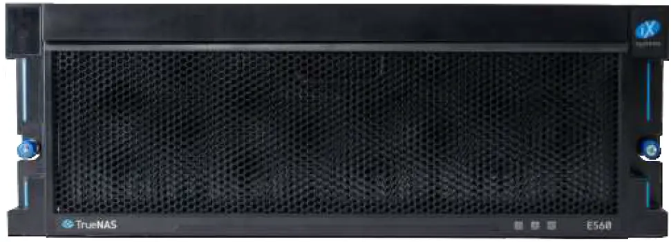
- ES60 Bezel

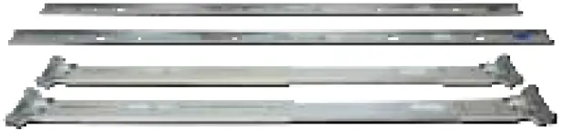
- Set of rackmount rails. The rails have a specific front end, identified by a label visible on the left above. The front ends of the rails must be installed facing the front of the rack.

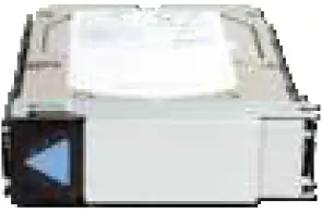
- Up to 60 drive trays with installed hard drives, shipped separately.

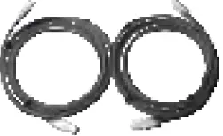
- Two 3-meter Mini SAS HD to Mini SAS HD cables.

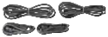
- Accessory kit with 2 IEC C13 to NEMA 5-15P power cords, 2 IEC C13 to C14 cords, and a set of velcro cable ties.
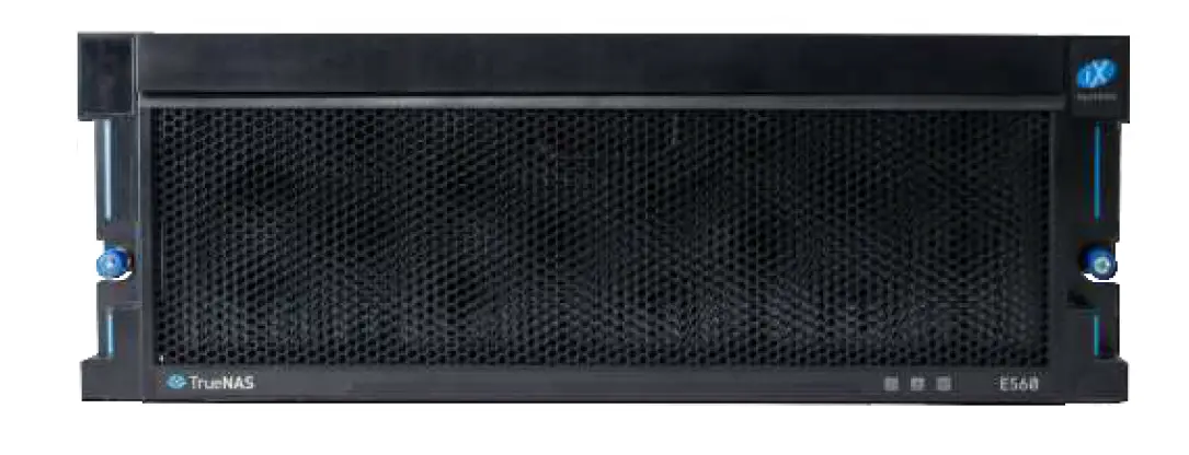
Become Familiar with the ES60
Indicators on the front panel show power, fault, and locate ID. The fault indicator is on during the initial power-on self-test (POST) or when the TrueNAS software has issued an alert.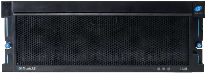 Front Panel Indicators
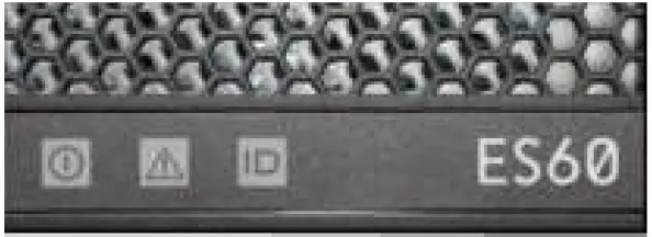 The ES60 has two expansion controllers in a side-by-side configuration.
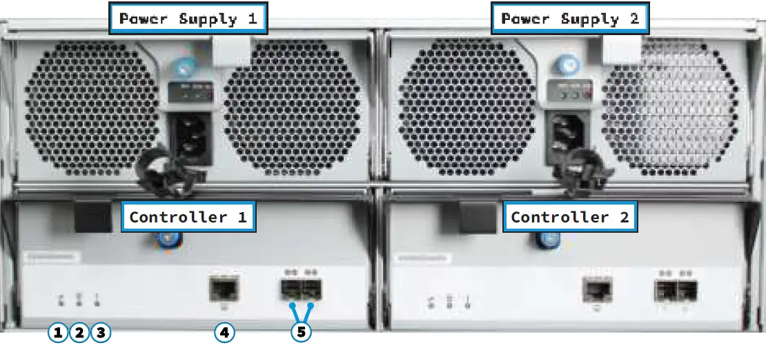
- Power indicator
- Alarm indicator
- Locate ID
- Management port (not used)
- HD Mini SAS3 connectors
Rail Kit Assembly
Separate Cabinet Rails from Rack Rails
Each rack rail includes an inner cabinet rail that must be removed. Extend the cabinet rail as shown below until the white release tab is exposed. Slide the white release tab to the right to release the cabinet rail. Remove the cabinet rail from the rack rail. Repeat the process for the second rail.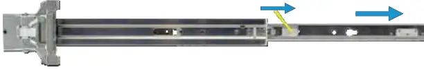
Mount Cabinet Rails
The cabinet rails are mounted on each side of the system. Align the cabinet rail keyholes with the posts on the side of the chassis. Slide the rail towards the rear of the system until the metal tab clicks and secures the rail in place. Repeat this process on the other side.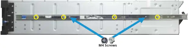
Mount the Rack Rails
The ES60 occupies 4U of rack space. The rails are mounted in the center 2U of that space. Cage nuts for racks with square and round holes are included. Install four cage nuts inside the rack, two where the rails attach to the front of the rack, and two at the rear. Align each cage nut with the others, both front to back and left to right. The cage nuts provide an attachment point inside the rack for the rail screws. The rail ends are stamped Front and Rear. Place one rail in the rack with the Front stamp at the front facing out-wards. The Rear stamp goes at the back of the rack. Align the pins on both rail ends with the mounting holes in the rack. Make sure the cage nuts line up with the rail holes. Push the pins in to the rack holes until they lock in place. Use the provided screws to secure the rails to the cage nuts.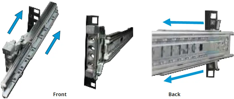
Mount the Unit in the Rack
Caution: Two people are required to safely lift the chassis for rack installation or removal. Do not install drives until after the chassis has been installed in the rack, and remove all drives before removing the chassis from the rack.
Lift the ES60 with attached cabinet rails and align the cabinet rails with the inside front of the rack rails.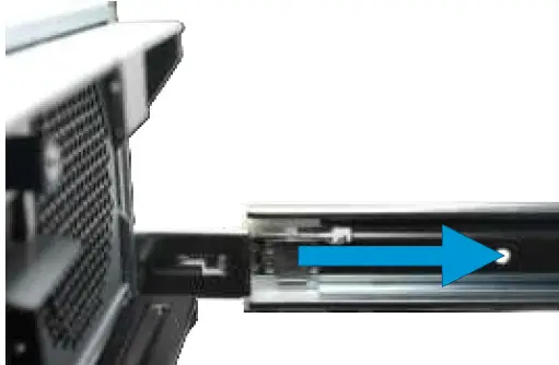 Carefully slide the ES60 forwards into the rack rails until the unit stops (1). Locate the blue tabs on the inside of the cabinet rails. Slide the tabs towards the front of the ES60 and hold them in place (2). Push the chassis into the rack until the ears are flush with the front of the rack (3). The thumbscrews on the ears are used to secure the unit in the rack after drive trays have been installed (4).
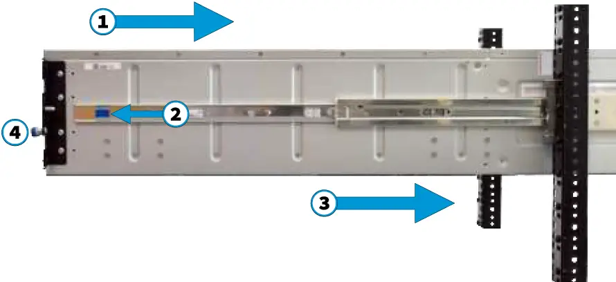
Drive Tray Installation
Do not install the drives until the chassis has been installed in the rack.
Remove Top Cover
Slide the unit out on the rails. Unscrew the cover screws to unlock the top cover (1). Slide the top cover forwards, then lift it off (2).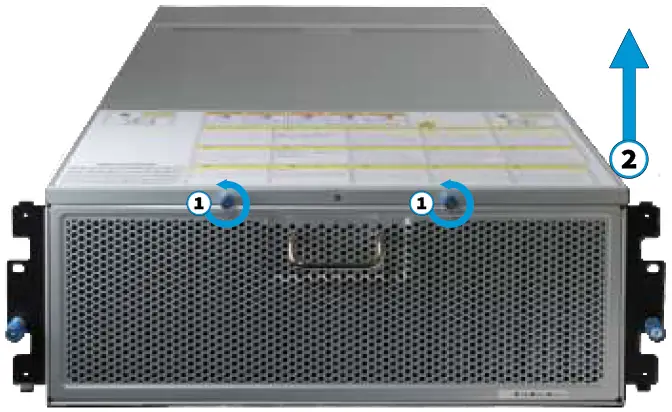
Install Drive Trays
TrueNAS systems only support qualified HDs and SSDs. Contact the Sales Team for more drives or replacements. Adding unqualified drives to the system voids the warranty. Call Support if drives are improperly installed in trays. To add a new drive into an empty tray, place the tray on a flat surface (1) and push the hard drive into the tray (2). Make sure the connector is at the rear of the tray.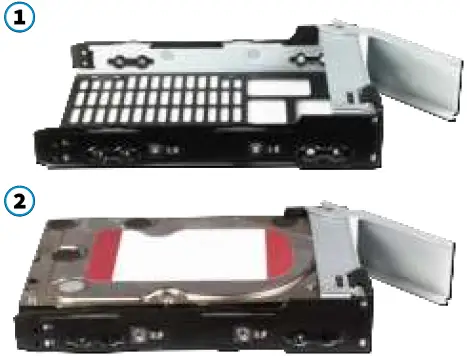 Drive trays are used to mount drives in the chassis. Each drive tray has LEDs that denote its current status.
| Drive Tray LED’s | |
| Light Color/Behavior | Status |
| Solid Blue | Normal/Hot Spare |
| Blinking Blue | Activity |
| Solid Amber | Issue/Fault/Identify |
| Note for Samsung 1643a 2.5” SSDs: Drive tray LED’s will only activate during drive activity or when there is a drive fault. | |
Drive trays are used to mount drives in the array.
A standard drive tray installation order simplifies support and is strongly recommended: install SSD drives for SLOG first, if present. Follow this with SSD drives for L2ARC, if present, then hard drives or SSD drives for data storage. Install the first drive tray in the front left drive bay. Install the next drive tray to the right of the first. Install remain-ing drive trays to the right across the row. After a row is filled with drives, move back to the next row and start again with the left bay. A label on the front left of the lid shows the preferred order of drives. Slide the tray button left to open the latch. Carefully lower the drive tray into a drive bay until the latch begins to move into place. Push the latch down until it locks into place.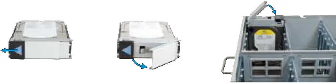 For proper air flow and cooling, the entire first row of drive trays must be installed. The top cover must also be in place when the unit is on.
ES60 Cable Management Arm
The included cable management arm (CMA) is not required for operation. If desired, the CMA can be used to help organize the ES60 power and data cables.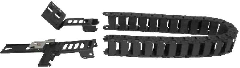 The tabs along the side of the flex housing can be unclipped from the top, the bottom, or removed entirely.
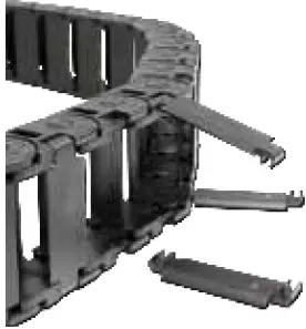
Install the Cable Management Arm
Note: You can only use the Cable Management Arm if your rackmount rail depth is between 27.5” and 31”.
There are two attachment posts on the left rear side of the ES60 for the CMA. Pulling the units lightly out of the rack can make these posts more accessible. Align the holes on the CMA chassis bracket with the posts. Slide the cable management arm forwards and pull the lever on the latch upwards to lock the bracket into place.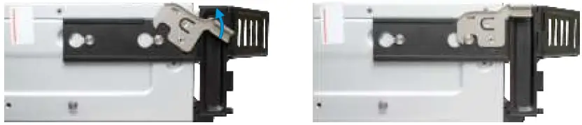 Locate the end of the flex housing with exposed pins. Un-clip and open the two tabs closest to the end, allowing the flex housing to compress enough to fit into the bracket holes. Press the flex housing firmly into the bracket until the pins seat in the holes.
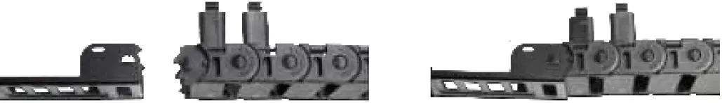 Remove the two screws already attached to the side of the CMA rail bracket. Align the screw holes with the holes in the rear of the left cabinet rail and attach the bracket to the rail with the screws.
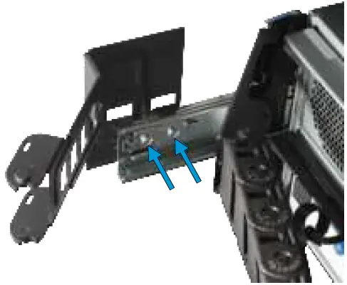 Locate the end of the flex housing with exposed holes. Un clip and open the two tabs closest to the end, allowing the flex housing to expand enough to fit over the bracket pins. Press the flex housing firmly into the bracket until the holes seat on the pins.
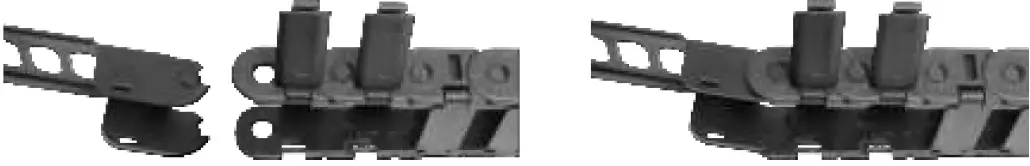 Completed Cable Management Arm assembly:
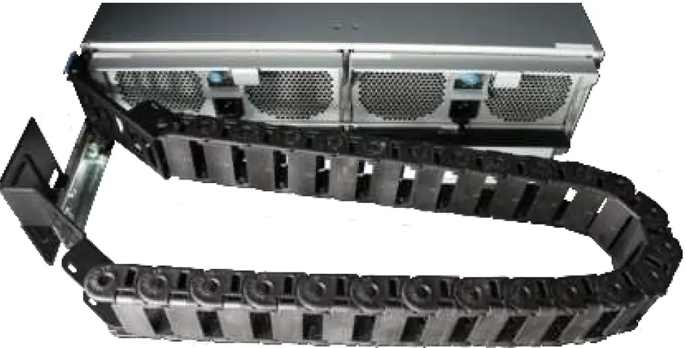 Power and data cables are routed through the flex housing. The tabs can be opened or removed to allow access or space for cable ends. Leave some slack in the cables at both ends to allow for movement of the arm and chassis.
Connect Power Cables
We recommend turning your TrueNAS system off before connecting the expansion shelf to ensure all pools and drives are visible when you boot the TrueNAS system.
- Do not plug the power cords into a power outlet yet.
Connect a power cord to the back of one power supply, pressing it into the plastic clamp and pressing on the tab to lock it in place. Repeat the process for the second power supply and cord. Plug both power cords into outlets. The ES60 will turn on.
- Wait two minutes for the drives to start.
If you turned off the TrueNAS system, power it back on.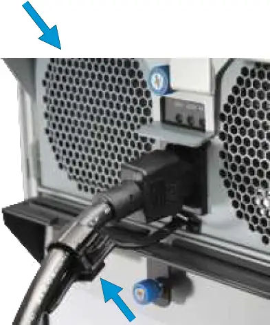 Service and Management ports are not used during normal operation. Do not connect anything to them.
Connect SAS Cables
Plug the ES60 power cords into power outlets. Wait two minutes for the drives to start. The ES60 is compatible with several TrueNAS systems. Typical SAS cable connections for connecting one or two ES60 units to TrueNAS High Availability (HA) systems are shown here. To set up SAS between your TrueNAS system and Expansion Shelves, cable the first port on the first TrueNAS Controller to the first port on the first Expansion Shelf Controller. High Availability systems require another cable from the first port on the second TrueNAS Controller to the first port on the second Expansion Shelf Controller. We DO NOT recommend other cabling configurations. Contact iX Support if you need other cabling methods.
Warning: When setting up your SAS connections, please adhere to the wiring examples in this guide. Connecting expansion shelves incorrectly will cause errors. Never cable a single controller to different expanders on the same expansion shelf.
X-Series
X20 with one ES60 Expansion Shelf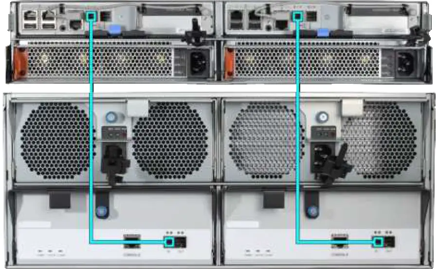
R-Series
R20
R20 with a single ES60 Expansion Shelf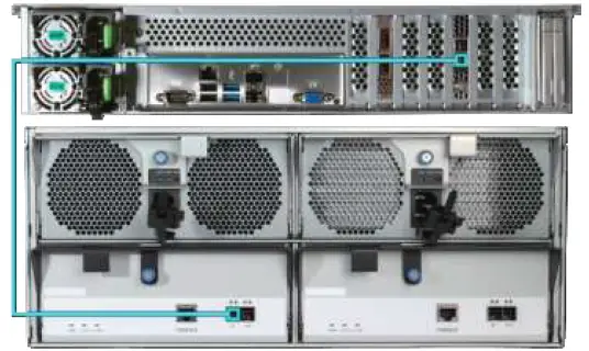 R20 with a single ES60 Expansion ShelfR20 with two ES60 Expansion Shelves
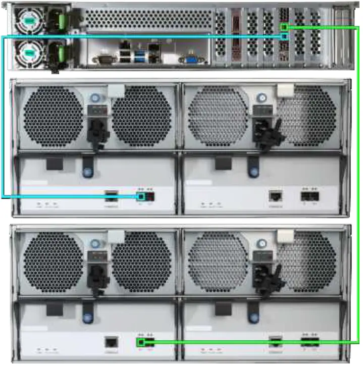
R40
R40 with a single ES60 Expansion Shelf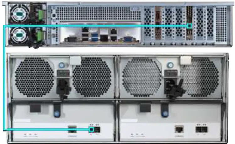 R40 with two ES60 Expansion Shelves
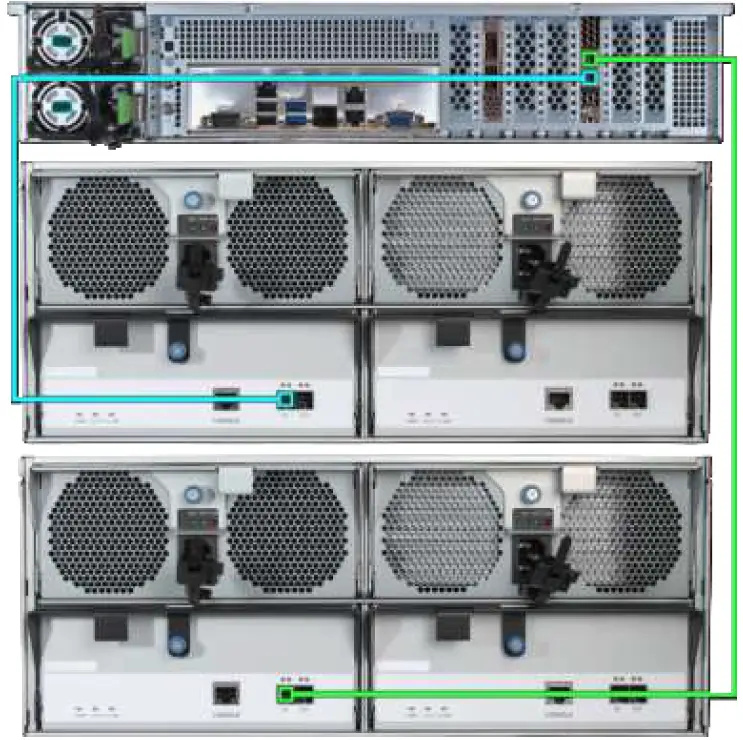
R50
R50 with a single ES60 Expansion Shelf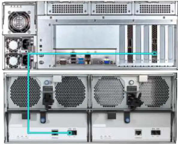 R50 with two ES60 Expansion Shelves
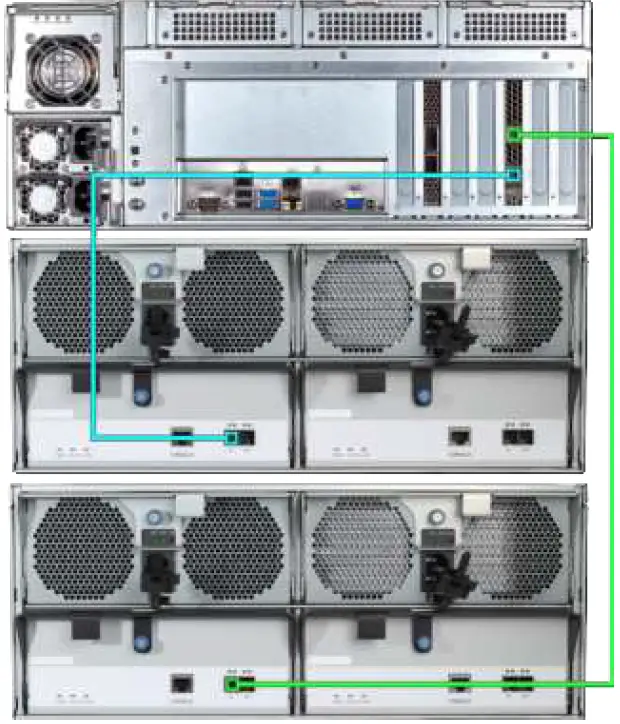
M-Series
M40
M40 with a single ES60 Expansion Shelf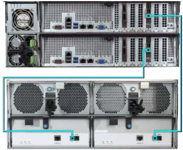 M40 with two ES60 Expansion Shelves
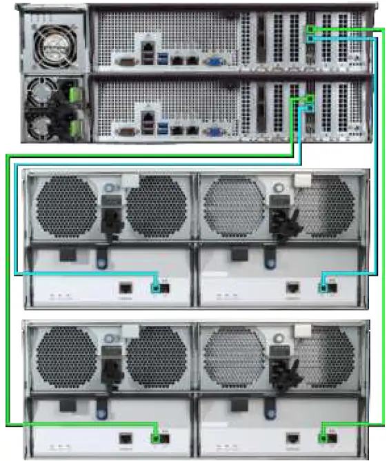
M50 and M60
M50/M60 with a single ES60 Expansion Shelf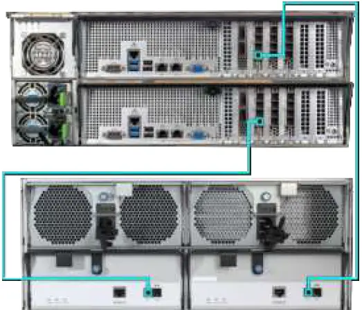 M50/M60 with three ES60 Expansion Shelves. The M50 can support up to 8 total Expansion Shelves with the use of additional SAS cards. The M60 can support up to 12 total Expansion Shelves with the use of additional SAS cards.
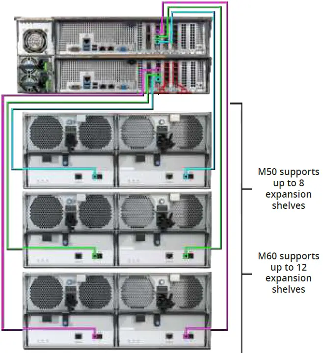
Install Bezel (Optional)
The included bezel is not required for operation. Line up the screw holes on the back of the bezel with the screw holes on the ears of the ES60. Install one upper screw from the back side of the left ES60 ear, then install a lower screw from the back of the right ES60 ear. Install the remaining two screws following the same diagonal pattern.
Additional Resources
The TrueNAS Documentation Hub has complete software configuration and usage instructions. Click Guide in the TrueNAS web interface or go directly to:
https://www.truenas.com/docs/
Additional hardware guides and articles are in the Documentation Hub’s Hardware section:
https://www.truenas.com/docs/hardware/
The TrueNAS Community forums provide opportunities to interact with other TrueNAS users and discuss their con-figurations:
https://www.truenas.com/community/
Contacting iXsystems
For assistance, please contact iX Support:
| Contact Method | Contact Options |
| Web | https://support.ixsystems.com |
| [email protected] | |
| Telephone | Monday-Friday, 6:00AM to 6:00PM Pacific Standard Time:
|
| Telephone | Telephone After Hours (24×7 Gold Level Support only):
|


