![]() PROFESSIONAL WATER PRODUCTS
PROFESSIONAL WATER PRODUCTS
Vario + 1100 Frequency Inverter
User Guide
AQUAFORTE
Thank you for purchasing our frequency inverter. Please read the manual carefully before installing or using it and keep it for future reference after installation.
SAFETY SYMBOLS
| Read and keep the manual | |
| Warning | |
| Electric shock or injuries to people | |
| Do not touch the heat sink | |
| No littering |
IMPORTANT SAFETY INSTRUCTIONS
![]() To make the best use of this energy-saving device and to avoid the potential risk of fire, electrical shock, SERIOUSinjuriesto people, or damaged property, please read this user guide carefully before installation and keep it for future reference.
To make the best use of this energy-saving device and to avoid the potential risk of fire, electrical shock, SERIOUSinjuriesto people, or damaged property, please read this user guide carefully before installation and keep it for future reference.
This device can ONLY be used with pool pumps with a permanent split capacitor motor. Below shows a typical single-speed swimming pool pump motor.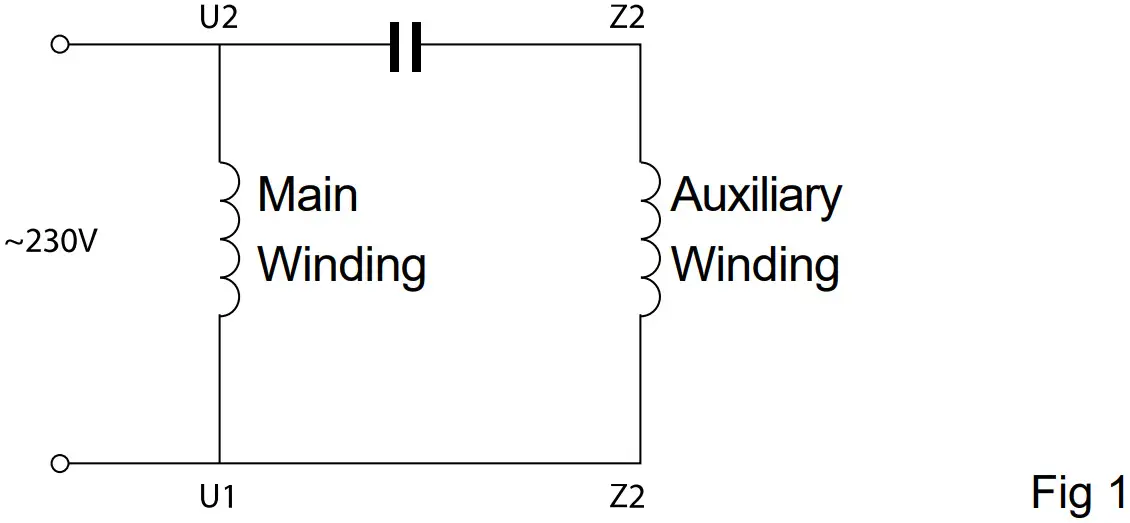 Running Capacitor
1.1 It is NOT compatible with:
a. Single phase motors with centrifugal switch
b. Pool pump motors with start relays or switch
c. Series or DC motors
d. Pool pump motors with faults in their rotors or capacitors
e. Shaded-pole asynchronous motors
1.2 An RCD with a rated residual current not exceeding 30mA must be used with this product.![]() If you are not sure of the compatibility of your pool pump with this device, please contact your supplier or manufacturer before proceeding with the installation.
If you are not sure of the compatibility of your pool pump with this device, please contact your supplier or manufacturer before proceeding with the installation.
TECHNICAL DATA
| Model | Vario+1100 | Dimension |
| Input power | 1 phase AC | 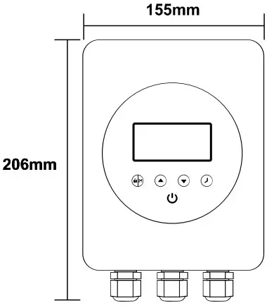 |
| Input voltage | 220~240V | |
| Input frequency | 50Hz | |
| Output power | Max 1.1kW | |
| Output Voltage | 1ph, 0~240V | |
| Pump type | Single phase | 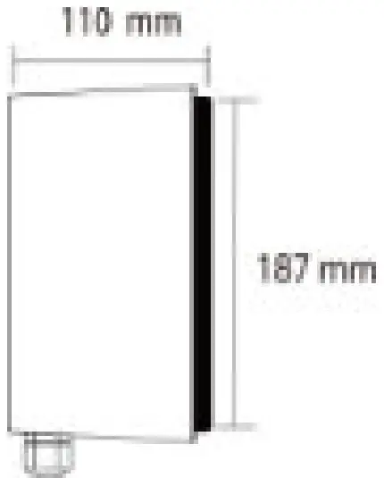 |
| Max. current | Max 6A | |
| Speed range | 1200~2900 rpm | |
| Cooling | Heat sink | |
| Net Dimension (L*H*W) | 187*110*155mm | |
| Gross/Net Weight | 3.2/2.65Kg |
BEFORE INSTALLATION
![]() Upon receipt of the device, check for any damages on the packaging or product. DO NOT proceed with the installation if any damage is found, contact your supplier. Do not use extension leads with the device. Thiscanposea danger particularly in the vicinity of a swimming pool.
Upon receipt of the device, check for any damages on the packaging or product. DO NOT proceed with the installation if any damage is found, contact your supplier. Do not use extension leads with the device. Thiscanposea danger particularly in the vicinity of a swimming pool.
Make sure the place you choose for installation meets the following conditions:
– Ambient temperature from -10~42°C
– 45 to 90 percent relative humidity, non-condensing
– Below 1000m above sea level
– No direct sunlight
– Good ventilation
For efficient cooling, please make sure it is installed with a minimum clearance surrounding it (Fig2), a blocked ventilation or an enclosed space with limited airflow may cause overheating or potentially cease working of the unit.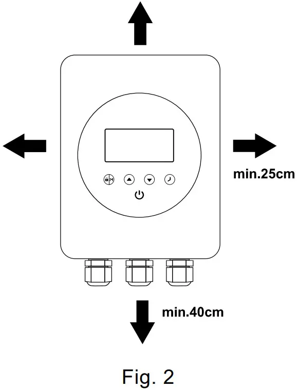
CONNECTING TO POOL PUMP
Please follow these steps and the wiring diagram for the correct connection. The warranty may be compromised if the device is not installed in accordance with instructions escribed in this manual
Only 1 pump can be connected to the inverter. Please do not connect any other appliance to the output.
Mark the hole locations on the wall, install the expansion plugs supplied, fit in the screws and hang the device on screws.
4.1 Turn off all electrical supplies to the pool pump, and unplug it from the main switch or at the chlorinator which provides electrical power to the pump.
4.2 Plug the pool pump into the device’s power outlet (marked PUMP CONNECTION ONLY).
4.3 Plug the device into the main switch/chlorinator/timer connection where the pump was originally plugged into.
4.4 Switch all power back on.
4.5 Ensure chlorinator/timer is active.
4.6 Now the device is ready to run.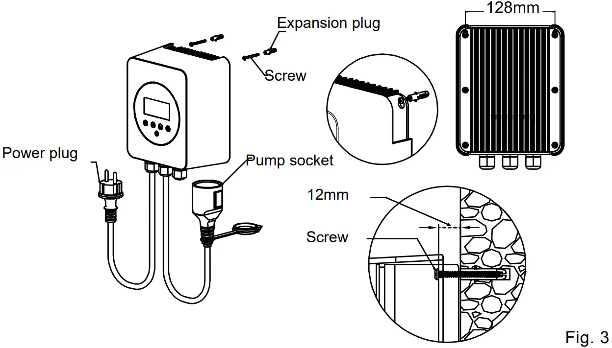 The above figure is for reference only, plugs or sockets may vary for a different markets.
If you do not require a power plug for installation, wire the device as shown in Fig.4, please.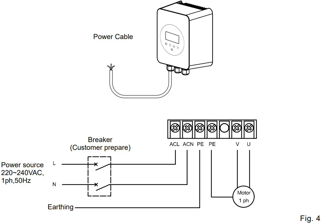
![]()
Do not touch the heat sink while the device is in operation or until at least 30 mins after it has been switched off. Keep it out of reach of children.
![]() Because of the high voltage conversion components contained in the device, do not try todisassemble or replace any components in case of malfunction or breakdown. Before serving on the unit, wait till the power light is turned off or at least 3 minutes after power plug has been plugged off from the input supply.
Because of the high voltage conversion components contained in the device, do not try todisassemble or replace any components in case of malfunction or breakdown. Before serving on the unit, wait till the power light is turned off or at least 3 minutes after power plug has been plugged off from the input supply.
SETTING & OPERATION
5.1 Control panel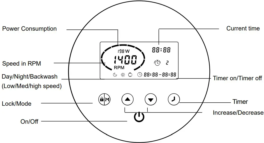 5.2 Mode selection
The frequency inverter has 3 modes(speed ranges). You can either run your pump at a constant speed choosing from “M” or set up 4 timers for daily operation, each with an individual speed.
| Mode | Speed range | Default speed |
| Night (Low) | 1200~1650 rpm | 1400 rpm |
| Day (Medium) | 1700~2400 rpm | 2000 rpm |
| Backwash (High) | 2450~2900 rpm | 2900 rpm |
| ① When the plugin, lights on, ② Up on start, the pump will run at a maximum speed (2900 rpm) for a one-minute self-priming. ③ Press | 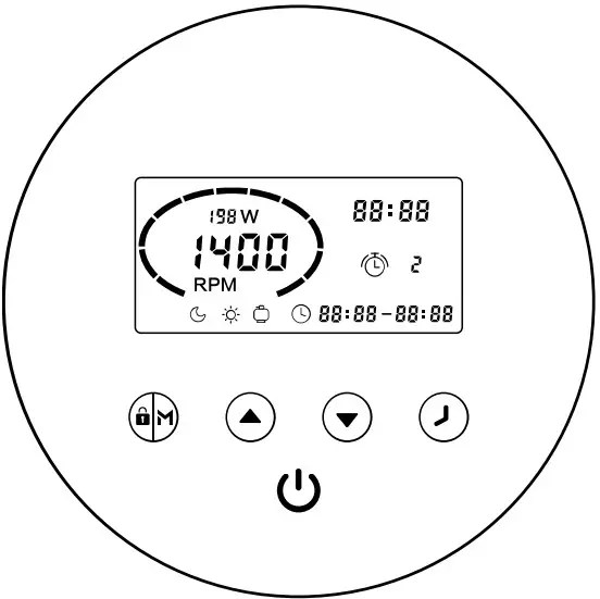 |
Upon completion of self-priming, the pump will automatically switch to the speed pre-set,![]() indicates the pump is running and showing current RPM and power consumption.
indicates the pump is running and showing current RPM and power consumption.
5.3 Timer setting
To run the pump at a different time or speed to take advantage of electricity tariffs during the day, you can set up to 4 timers.
Step1: Press to ![]() enter timer setting
enter timer setting
Step2: Use ![]() or
or ![]() set the current time. Press
set the current time. Press ![]() To moves the cursor to the next setting. Press
To moves the cursor to the next setting. Press ![]() to Choose a speed range for timer 1, use
to Choose a speed range for timer 1, use ![]() or
or ![]() to decide on a specific speed if needed.
to decide on a specific speed if needed.
Step3: Repeat the above steps to set the other 3 timers
Step4: Hold ![]() for 3 seconds or wait 10 seconds to save the setting automatically. A flashing
for 3 seconds or wait 10 seconds to save the setting automatically. A flashing ![]()
![]() indicates the device is waiting for the start time.
indicates the device is waiting for the start time.
Step5: press ![]() or
or ![]() check 4 timers, and make sure there is no invalid setting.
check 4 timers, and make sure there is no invalid setting.
* Overlap setting of time will be considered invalid, the device will only run based on the previous valid settings.
* During timer setting, if you want to abandon it, hold ![]() for 3 seconds.
for 3 seconds.
Note:
* If inactivate in 1 minute, the screen will lock automatically. Hold ![]() for 3 seconds to unlock the device.
for 3 seconds to unlock the device.
* Thedevicehaspower-off memory, the operation will resume upon power restoration.
* Under OFFmode, hold ![]()
![]() for 3 seconds to retrieve the factory setting.
for 3 seconds to retrieve the factory setting.
5.4 External control
External control can be enabled via the following contacts. However even if it’s working via external control, Press ![]() can stop the device. Please do not apply voltage to these inputs.
can stop the device. Please do not apply voltage to these inputs.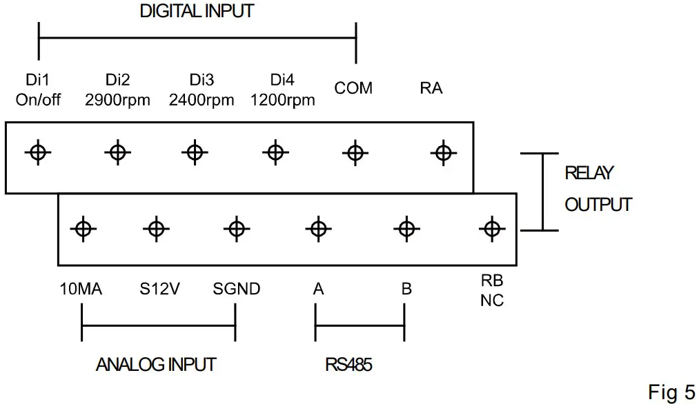 E.g.: To enable external speed control via digital input, connect one of the digits from Di2/3/4 to COM.
5.5 Parameter setting
Under OFF mode, hold ![]()
![]() for 3 seconds to enter the parameter setting.
for 3 seconds to enter the parameter setting.
| Parameter | Description | Default setting | Setting range |
| 1 | Priming time | 1 minute | 1~10min, by 1 increment |
| 2 | Minimum RPM | 1200RPM | 1200~2000RPM, by 100RPM increment |
PROTECTION & ERROR CODE
| Item | Code | Description | Analysis |
| 1 | E001 | Abnormal input voltage | Not faulty |
| 2 | E002 | Output over-current | Not faulty |
| 3 | E101 | Heat sink overheat | Contact your supplier |
| 4 | E102 | Heat sink sensor error | Contact your supplier |
| 5 | E103 | Master driver board error | Contact your supplier |
| 6 | E201 | Circuit board error | Contact your supplier |
| 7 | E202 | Master board EEPROM reading failure | Contact your supplier |
| 8 | E203 | RTC time reading error | Contact your supplier |
| 9 | E204 | Keyboard EEPROM reading failure | Contact your supplier |
| 10 | E205 | Communication error | Contact your supplier |
| 11 | AL01 | Auto speed reduction against high temperature | Contact your supplier |
When an error code appears, the device will stop working, to resume operation, unplug the device and plug it in again. AL01 is not an error indication when it appears, the product will switch automatically to a lower speed for self-protection against high interior temperature, when the temperature drops back to 65°C, the product will resume preset speed.
EXEMPTION
Under no circumstances should the manufacturer be held liable for any consequences resulting from inappropriate, incorrect installation, or mismatching of the product to pool pumps that are not compatible.
The manufacturer reserves the right to change the specification of the product or its performance or the contents of the User Guide without notice in case of a technical upgrade.
WEEE LEGISLATION
![]()
When disposing of the product, please hand it over to a designated collection point for the recycling of waste electrical and electronic equipment. The separate collection and recycling of waste equipment at the time of disposal will help ensure that it is recycled in a manner that protects human health and the environment. Contact your local authority for information on where you can drop off your water for recycling.
AquaForte is a trademark of SIBO Fluidra Netherlands BV, Doornhoek 3950, 5465TC, VEGHEL,
Aqua Forte ist eine Marke von SIBO Fluidra Netherlands BV, Doornhoek 3950, 5465TC, VEGHEL
www.aqua-forte.com,
[email protected]


