ST com SL-PTOOL1V1 Compact Reference Design for Low Voltage Brushless Power tools

Introduction
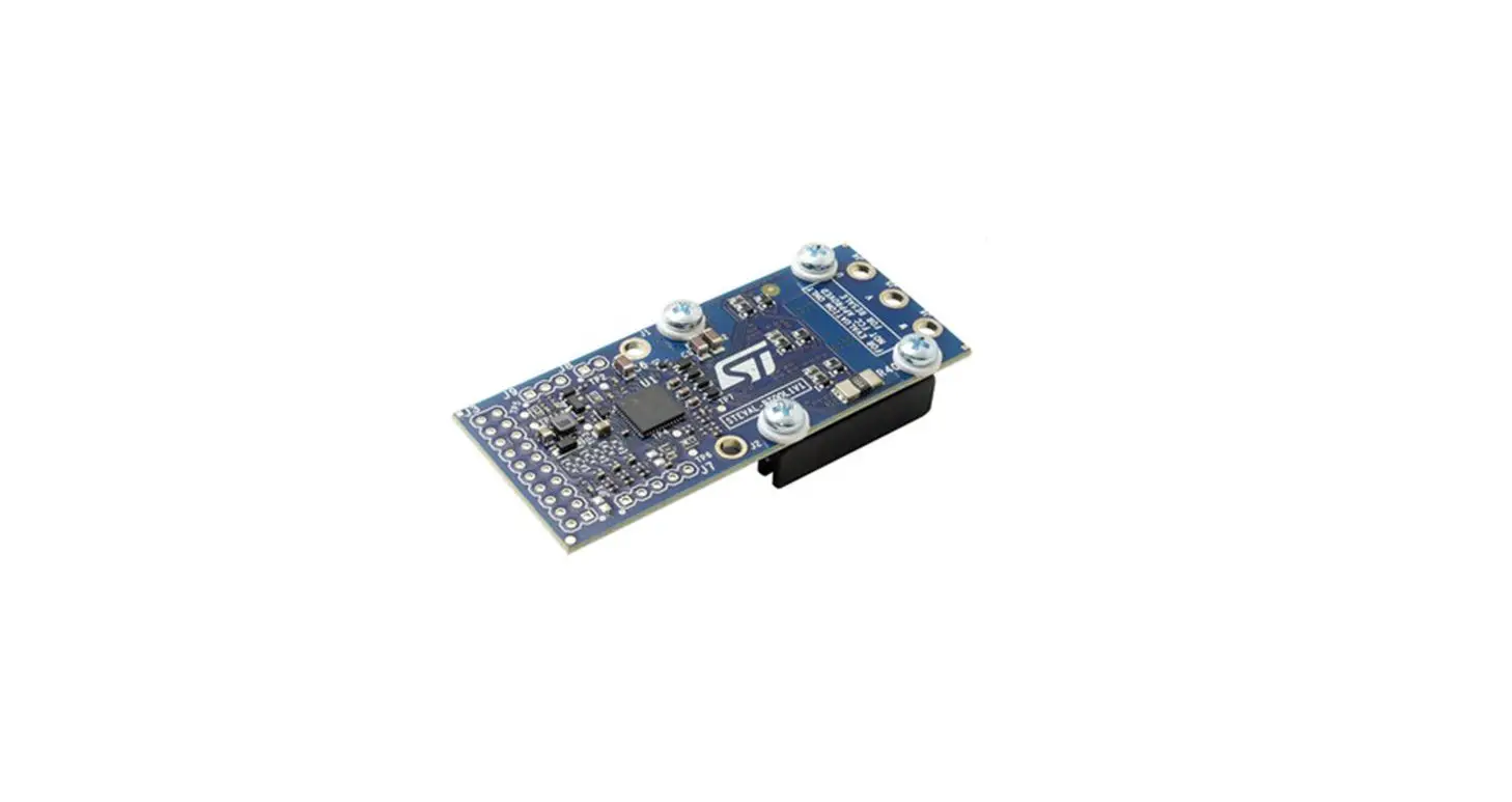
This STEVAL-PTOOL1V1 compact 70 mm x 30 mm reference design board is tailored for low voltage power tools driven
by 3-phase brushless motors, supplied by 2S to 6S batteries. The design is based on the STSPIN32F0B controller and STL180N6F7 (or STL220N6F7) power MOSFET.
The board is ready for sensorless and sensored FOC, and can be configured for six-step sensorless control through available BEMF sensing circuitry. The firmware example included in STM32 Motor Control SDK (X-CUBE-MCSDK-Y) uses position feedback from Hall effect sensors, with debugging and programming capability available through the SWD interface and the direct firmware update feature.
The board can deliver up to 15 A continuous current, thanks also to the optimal thermal dissipation provided by an embedded heatsink. It embeds a fast power-on circuit that connects and disconnects the battery, allowing standby consumption below 1 μA for extended battery duration. Several protection features are included, such as thermal shutdown, undervoltage lockout, overcurrent protection with programmable threshold and reverse biasing of power stage outputs.
This reference design is predominately intended for power tools, but is very suitable for any battery-powered application involving similar architecture, rating and performance. A potentiometer input for speed variation is available.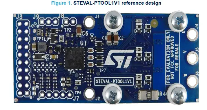
Getting started
Safety precautions
Danger: Some of the components mounted on the board could reach hazardous temperature during operation.
Caution: While using the board:
- Do not touch the components or the heatsink
- Do not cover the board
- Do not put the board in contact with flammable materials or with materials releasing smoke when heated
- After operation, allow the board to cool down before touching it
- Adding a bulk capacitor is highly recommended to prevent a not stabilized power supply or voltage overshoots at power-on which could damage the device
Overview
The STEVAL-PTOOL1V1 implements a single-shunt topology and features:
- 7 – 45 V motor voltage rating supported
- Recommended for power tools supplied from 2S to 6S batteries
- Output current up to 15 Arms
- STSPIN32F0B advanced 3-phase motor controller tailored for single-shunt applications
- STL180N6F7 60 V, 1.9 mΩ N-channel power MOSFET
- Ultra-low standby current below 1µA thanks to an external turn-on/off trigger
- Heat sink for improved power dissipation
- Extremely compact footprint (70 mm x 30 mm)
- Input connector for Hall effect sensors and encoder
- Plug-and-play capability through six-step firmware with Hall effect sensor feedback
- Six-steps sensorless control available through dedicated BEMF sensing circuitry and sensorless/sensored Field Oriented Control
- Speed regulation through an external trimmer
- Protections: thermal shutdown, UVLO, overcurrent and reverse biasing of power stage outputs
- SWD debug interface and direct firmware update (DFU) via UART
Hardware and software requirements
To use the STEVAL-PTOOL1V1 board, you need:
- a Windows (7, 8 or 10) PC
- ST-LINK debugger/programmer for STM32
- the STM32 Motor Control SDK (X-CUBE-MCSDK-Y)
- one of the following IDEs:
- IAR Embedded Workbench for ARM
- Keil microcontroller development kit (MDK-ARM-STR)
- STM32CubeIDE
- a power supply with output voltage between 7 and 45 V (70 mA, max. DC current PCB absorption only in run-mode)
- a three-phase brushless motor in the current and voltage ranges of the power supply and the STSPIN32F0B
Hardware description and configuration
Figure 2. STEVAL-PTOOL1V1 overview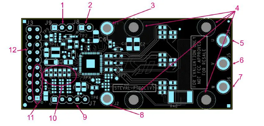
- Speed regulation trimmer
- Power-on trigger
- Positive battery supply
- Holes for mounting the heatsink
- Motor phase connector
- Motor phase connector
- Motor phase connector
- Negative battery supply
- Hall sensor connectors
- BEMF sensing circuitry
- SWD interface
- GPIOs
MCU GPIOs mapped on J3 connectors
| Connector | Pin no. | Signal | Remarks |
|
J3 | 1 | NRST | SWD-RESET signal |
| 2 | Ground | ||
| 3 | PA13 | SWD-CLK signal | |
| 4 | PB1 | ||
| 5 | Ground | SWD-GND signal | |
| 6 | PA7 | BEMF divider enabler | |
| 7 | PA14 | SWD-DIO signal | |
| 8 | PA6 | ||
| 9 | VDD | ||
| 10 | PA5 | ||
| 11 | BOOT0 | ||
| 12 | PA4 | Current feedback |
| Connector | Pin no. | Signal | Remarks |
|
J3 | 13 | PA15 | |
| 14 | PA3 | Speed regulation trimmer input | |
| 15 | PB6 | ||
| 16 | PC14 | ||
| 17 | PB7 | ||
| 18 | PC15 | ||
| 19 | PB8 | ||
| 20 | PB9 |
Operation mode and sensing topology selection
The STEVAL-PTOOL1V1 supports 6-step sensorless and sensored algorithms.
According to the algorithm used, you can change the board configuration by soldering the missing components as per the table below.
Table 2. Hardware configuration
| Driving technique | Hardware changes |
| Sensorless Voltage mode (see Figure 3) | • BEMF sensing circuitry must be populated • R10, R11 and R12 must be unsoldered |
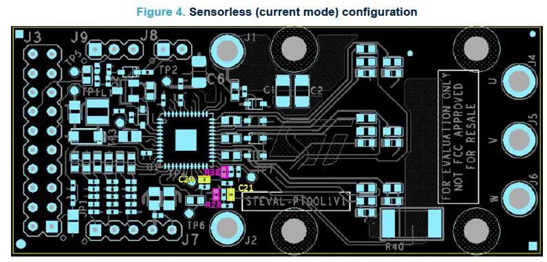
| Sensorless Current mode | • BEMF sensing circuitry must be populated • R10, R11 and R12 must be unsoldered • C20 and C21 can be populated to improve current feedback filtering performances • R28 and R38 can be populated to offset or partition current feedback signal |
| Hall sensors Voltage mode | Default – no change required |
| Hall sensors Current mode (see Figure 4) | • C20 and C21 can be populated to improve current feedback filtering performances and/or to offset/partition • R28 and R38 can be populated to offset or partition current feedback signal |

Current sensing
The STEVAL-PTOOL1V1 board mounts a shunt resistor to sense the current flowing into the motor phases. The resistor is connected to an amplifier integrated in the STSPIN32F0B for signal conditioning before forwarding the sensed value to the integrated comparator. Filtering parameters and gain factor can be changed through R26 and C20. The filtered signal (current feedback) is routed to J3-12.
STSPIN32F0B integrates a comparator for OC detection. When an OC event is triggered, the OC comparator output signals the OC event to the MCU PB12 and PA12 inputs (BKIN and ETR). The comparator internal OC threshold can be set via MCU (PF6 and PF7 ports as per the table below). The corresponding current limit setting depends on the shunt resistor and signal conditioning values.
Table 3. OC thresholds
| PF6 | PF7 | OC threshold [mV] | Default current limit [A] |
| 0 | 0 | N.A. | |
| 0 | 1 | 100 | 20 |
| 1 | 0 | 250 | 50 |
| 1 | 1 | 500 | 100 |
Hall effect sensors and encoder connector
The STEVAL-PTOOL1V1 board interfaces the digital Hall effect sensors or encoder mounted on the motor with the STM32 Nucleo development board through J7 connector.
The connector provides:
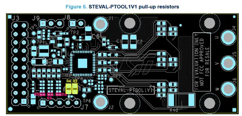
- pull-up resistors (R6, R8, R9) for open-drain and open-collector interfacing
Remove the pull-up resistors in case of push-pull outputs (see Figure 5) - the encoder/sensor supply is normally connected to the battery voltage but the default setting can be changed by removing R3 and short-circuiting R4 allowing VDD supply (see Figure 5)
Table 4. J7 pinout
| Pin | Encoder | Hall effect sensor |
| 1 | A+ | Hall 1 |
| 2 | B+ | Hall 2 |
| 3 | Z | Hall 3 |
| Pin | Encoder | Hall effect sensor |
| 4 | Encoder power supply | Sensor power supply |
| 5 | Ground | Ground |
Speed trimmer
You can connect an external trimmer to J9 connector to provide the MCU with an analog signal used by the firmware as the setting point of the speed control loop.
The voltage ranges from 0 to 3.3 V (VDD) and increases by rotating the trimmer in clockwise direction.
Turn on/off circuitry
An external switch allows you to properly connect or disconnect the MCU and the battery, reducing the quiescent consumption to the lowest level. As soon as the switch is closed, the motor can be driven as required by the control algorithm.
The schematic section below shows the turn on/off trigger circuitry. By closing the trigger switch, the Q1 PMOS gate is forced low, connecting the battery to the control circuitry.
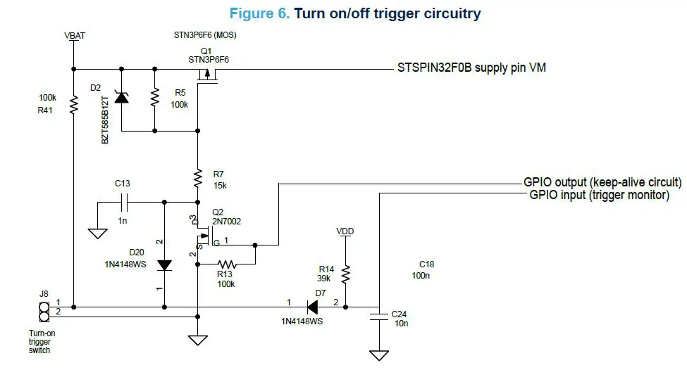
Keep-alive circuit
As soon as the Q1 PMOS connects the battery to the STSPIN32F0B and the VM rises above the turn on threshold, the power-up sequence starts and the integrated buck regulator performs the soft-start ramp supplying the MCU.
When the MCU is operative, you can keep the PMOS closed using Q2 NMOS which acts as an MCU driven switch parallel to the external trigger switch. Thus, the firmware takes control of the connection between the battery and the STSPIN32F0B allowing the code to perform a safe switch-off (for example, by braking the motor).
Set the GPIO output (PF0) at MCU initialization.
External trigger status detection
While the STSPIN32F0B is supplied by the keep-alive circuit, the actual status of the external trigger switch must be constantly monitored to execute the shutdown sequence when it is released.
The monitoring GPIO (PF1) is connected to the switch through D2 diode. As long as the switch is closed, the GPIO is forced low through D2. Releasing the switch, D2 turns off and the GPIO is pulled up by the resistor.
An interrupt to trigger the braking and stop the motor should be set on the rising edge of PF1.
Protection against reverse biasing from power stage outputs
The battery is always connected to the power stage while the control side is disconnected through the Q1 PMOS switch. Thus, the voltage of the power stage output (VOUT) can be higher than the control logic supply (VM) violating the AMR limit of the gate driving circuitry (VOUT max. = VM + 2 V).
The device is protected against this reverse biasing by the diodes between each output and the VM supply (D3, D4, D5 and D7).
How to use the board
Step 1. Check the mounting options according to the desired operation mode (see Section 2.1 Operation mode and sensing topology selection).
Step 2. Connect an external trigger switch to J8.
As an option, you can connect an external trimmer to J9 to vary the motor speed.
Step 3. Supply the board through J1 (positive) and J2 (ground).
Step 4. Download the pre-compiled code through the SWD interface.
Step 5. Connect the brushless motor phases to J4, J5 and J6.
Step 6. Develop your application using the firmware example included in STM32 Motor Control SDK (X-CUBEMCSDK- Y) as starting point.
Schematic diagrams
Figure 7. STEVAL-PTOOL1V1 schematic diagram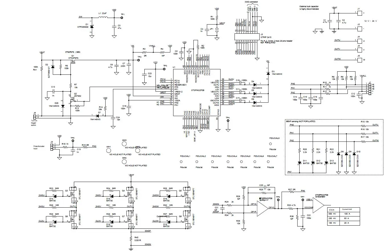
Bill of materials
Table 5. STEVAL-PTOOL1V1 bill of materials
| Item | Q.ty | Ref. | Part/Value | Description | Manufacturer | Order code |
| 1 | 2 | C1, C2 | 4.7µF Size 1206 50 V | SMT ceramic capacitor | Kemet | C1206C475K5PACTU |
| 2 | 1 | C3 | 47 µF Size 0805 6.3 V | SMT ceramic capacitor | Kemet | C0805C476M9PACTU |
| 3 | 2 | C4, C19 | 1 nF Size 0402 6.3 V | SMT ceramic capacitor | Murata | GRM155R61H102KA01D |
| 4 | 2 | C5, C18 | 100 nF Size 0402 6.3 V | SMT ceramic capacitor | Murata | GCM155R71C104KA55D |
| 5 | 1 | C6 | 4.7 µF Size 1206 50 V | SMT ceramic capacitor | Kemet | C1206C475K5PACTU |
| 6 | 1 | C7 | 220 nF Size 0402 50 V | SMT ceramic capacitor | Taiyo Yuden | UMK105BJ224KV-F |
| 7 | 3 | C10, C11, C17 | 1000 n Size 0603 16 V | SMT ceramic capacitor | TDK | C1608X7R1C105K080AC |
| 8 | 1 | C12 | 100 n Size 0402 16 V | SMT ceramic capacitor | Murata | GCM155R71C104KA55D |
| 9 | 1 | C13 | 1 n Size 0402 3.6 V | SMT ceramic capacitor | Murata | GRM155R61H102KA01D |
| 10 | 4 | C14, C15, C16, C22 | 100 p Size 0402 6.3 V | SMT ceramic capacitor | MULTICOMP | MC0402B101K250CT |
| 11 | 2 | C20, C21 | Size 0402 6.3 V | SMT ceramic capacitor (not mounted) | Any | |
| 12 | 1 | C23 | 10 µ Size 0805 16 V | SMT ceramic capacitor | Murata | GRM21BR61C106KE15L |
| 13 | 1 | C24 | 10 n Size 0402 6.3 V | SMT ceramic capacitor | Wurth Elektronik | 885012205012 |
| 14 | 1 | D1 | STPS0560Z SOD-123 | Schottky Rectifier | ST | STPS0560Z |
| 15 | 1 | D2 | BZT585B12T SOD523 | SMD Precision Zener Diode | Diodes Incorporated | BZT585B12T-7 |
| 16 | 5 | D3, D4, D5, D6, D7 | 1N4148WS SOD-323F | Small Signal Fast Switching Diode | Vishay | 1N4148WS-E3-08 |
| 17 | 3 | D8, D9, D10 | BZX585-C3V3 SOD-523 3.3 V | 3.3 V Zener Diode 300mW (not mounted) | Nexperia | BZX585-C3V3 or equivalent (NP) |
| 18 | 3 | D11, D12, D13 | BAT30KFILM SOD-523 30 V | Small Signal Schottky Diode (not mounted) | ST | |
| 19 | 6 | D14, D15, D16, D17, D18, D19 | BAT30KFILM SOD-523 30 V | Small Signal Schottky Diode | ST | |
| 1 | D20 | IN4148WS SOD-323 75V | General purpose diode | Vishay | 1N4148WS-E3-08 | |
| 20 | 1 | JP1 | SMT jumper | Any | ||
| 21 | 5 | J1, J2, J4, J5, J6 | Plated Hole 3 mm | Jumpers | Any |
| Item | Q.ty | Ref. | Part/Value | Description | Manufacturer | Order code |
| 22 | 1 | J3 | STRIP 2×10 2×10 pins | Strip connector 10×2 poles, 2.54 mm (not mounted) | Any | |
| 23 | 1 | J7 | STRIP 1×5 1×5 pins | Strip connector 5 poles, 2.54 mm (not mounted) | Any | |
| 24 | 1 | J8 | STRIP 1×2 1×2 pins | Strip connector 2 poles, 2.54 mm (not mounted) | Any | |
| 25 | 1 | J9 | STRIP 1×3 1×3 pins | Strip connector 3 poles, 2.54 mm (not mounted) | Any | |
| 26 | 1 | L1 | 22 µF, 580 mA, SMD 3 x 1.5 mm | Inductor | Bourns | SRN3015-220M |
| 27 | 1 | Q1 | STN3P6F6 SOT-223 | P-channel -60 V, 0.13 Ohm, -3 A STripFET F6 Power MOSFET | ST | |
| 28 | 1 | Q2 | 2N7002 SOT-23 | N-channel 60 V, 7.5 Ohm MOSFET | ST | 2N7002 |
|
29 |
6 |
Q3, Q4, Q5, Q6, Q7, Q8 | STL180N6F7 | N-channel 60 V, 1.9 mOhm, 120 A STripFET F7 Power MOSFET |
ST | |
|
STL180N6F7 | N-channel 60 V, 0.0012 Ohm typ., 260 A STripFET F7 Power MOSFET |
| ||||
| 30 | 2 | R1, R2 | 100 k Size 0402 1/16W 5 % | SMT resistor | Panasonic | ERJ2RKF1003X |
| 31 | 1 | R3 | 0 R Size 0805 0.1 W 5 % | SMT resistor | Yageo | RC0805JR-070RL |
| 32 | 1 | R4 | Size 0805 0.1 W 5 % | SMT resistor (not mounted) | Any | |
| 33 | 2 | R5, R41 | 100 k Size 0402 1/16 W 5 % | SMT resistor | Panasonic | ERJ2RKF1003X |
| 34 | 3 | R6, R8, R9 | 10 k Size 0402 1/16 W 5 % | SMT resistor | Panasonic | ERJ2RKF1002X |
| 35 | 1 | R7 | 15 k Size 0402 1/16 W 5 % | SMT resistor | Vishay | CRCW040215K0FKED |
| 36 | 3 | R10, R11, R12 | 1 k Size 0402 1/16 W 5 % | SMT resistor | Panasonic | ERJ2GEJ102X |
| 37 | 1 | R13 | 100 k Size 0603 1/16W 5 % | SMT resistor | TE Connectivity | CRG0603F100K |
| 38 | 1 | R14 | 39k Size 0402 1/16W 5 % | SMT resistor | Vishay | CRCW040239K0FKED |
| 39 | 3 | R15, R16, R17 | 10 k Size 0402 0.1 W 5 % | SMT resistor (not mounted) | Any |
| Item | Q.ty | Ref. | Part/Value | Description | Manufacturer | Order code |
| 40 | 1 | R18 | 1 k Size 0402 1/16W 5 % | SMT resistor | Panasonic | ERJ2GEJ102X |
| 41 | 1 | R19 | 0 R Size 0603 1/16W 5 % | SMT resistor | Panasonic | ERJ3GEY0R00V |
| 42 | 3 | R20, R21, R22 | 2.2 k Size 0402 0.1 W 5 % | SMT resistor (not mounted) | Any | |
| 43 | 6 | R23, R24, R25, R35, R36, R37 | 56 R Size 0603 0.1 W 5 % | SMT resistor | Vishay | CRCW060356R0FKEA |
| 44 | 2 | R26, R39 | 10 k Size 0402 1/16 W 1 % | SMT resistor | Panasonic | ERJ2RKF1002X |
| 45 | 1 | R27 | 0 R Size 0603 0.1 W 5 % | SMT resistor | Panasonic | ERJ3GEY0R00V |
| 46 | 2 | R28, R38 | Size 0402 1/16 W 1 % | SMT resistor (not mounted) | Any | |
| 47 | 2 | R29, R34 | 2 k Size 0402 1/16 W 1 % | SMT resistor | Panasonic | ERJ2RKF2001X |
| 48 | 3 | R30, R31, R32 | 10 R Size 0603 0.1 W 5 % | SMT resistor | Vishay | CRCW060310R0FKEA |
| 49 | 1 | R33 | 4.7 k Size 0402 1/16 W 1 % | SMT resistor | Panasonic | ERJ2GEJ472X |
| 50 | 1 | R40 | 0.001R Size 2512 3 W 1 % | SMT resistor | Bourns | CRE2512-FZ-R001E-3 or equivalent |
| 51 | 7 | TP1, TP2, TP3, TP4, TP5, TP6, TP7 | TP-SMD- diam1_27mm copper pad | SMD pad | Any | |
|
52 |
1 |
U1 | STSPIN32F0B VFQFPN48 7x7x1mm | Advanced single shunt BLDC controller with embedded STM32 MCU |
ST |
|
| 53 | 1 | 3386W-1-503L F | Potentiometer, 50Kohm, through hole, 3386 trimpot series | Bourns | 3386W-1-503LF | |
| 54 | 1 | Heatsink-29×2 9×8 mm | Heatsink-29x29x 8 mm | Fischer Elektronik | ICK SMD E 29 SA | |
| 55 | 1 | PCB | 30x70x1.55m m 30x70x1.55m m | 4 layer FR4-PCB cu Thikness 70micron, inner 35micron | Any | |
| 56 | 4 | 3x8mm 3x8mm | Vite metrica cilindrica M3 RS PRO, in Acciaio, 8mm | Wurth | 00463 8 | |
| 57 | 4 | 7X3.2X0.5mm 7X3.2X0.5mm | Nylon 6/6 UL94- V2 | STEAB | 5021/1 | |
| 58 | 1 | 3.2 W/m*K 150x150x0.5 mm self- adhesive | Thermal interface sheet | R.S. Pro | 707-4645 |
Revision history
Table 6. Document revision history
| Date | Version | Changes |
| 02-Oct-2020 | 1 | Initial release. |
| 14-Jan-2021 | 2 | Updated Section 1.1 Safety precautions, Section 3 How to use the board and Section 4 Schematic diagrams. |
| 03-Aug-2021 | 3 | Updated Introduction, Hardware and software requirements and How to use the board. |
| 11-Nov-2021 | 4 | Updated Section 4 Schematic diagrams. |
IMPORTANT NOTICE – PLEASE READ CAREFULLY
STMicroelectronics NV and its subsidiaries (“ST”) reserve the right to make changes, corrections, enhancements, modifications, and improvements to ST products and/or to this document at any time without notice. Purchasers should obtain the latest relevant information on ST products before placing orders. ST products are sold pursuant to ST’s terms and conditions of sale in place at the time of order acknowledgment.
Purchasers are solely responsible for the choice, selection, and use of ST products and ST assumes no liability for application assistance or the design of Purchasers’ products.
No license, express or implied, to any intellectual property right is granted by ST herein.
Resale of ST products with provisions different from the information set forth herein shall void any warranty granted by ST for such product.
ST and the ST logo are trademarks of ST. For additional information about ST trademarks, please refer to www.st.com/trademarks. All other product or service names are the property of their respective owners.
Information in this document supersedes and replaces information previously supplied in any prior versions of this document.
© 2021 STMicroelectronics – All rights reserved
References
 STMicroelectronics: Our technology starts with you
-
STMicroelectronics Trademark List - STMicroelectronics
-
BAT30 - 30 V, 300 mA SMD General purpose Signal Schottky Diode - STMicroelectronics
-
ST-LINK/V2 - ST-LINK/V2 in-circuit debugger/programmer for STM8 and STM32 - STMicroelectronics
-
STEVAL-PTOOL1V1 - Compact reference design for low voltage brushless power tools based on STSPIN32F0B - STMicroelectronics
-
STL180N6F7 - N-channel 60 V, 1.9 mOhm typ., 120 A STripFET F7 Power MOSFET in a PowerFLAT 5x6 package - STMicroelectronics
-
STL220N6F7 - N-channel 60 V, 0.0012 Ohm typ., 120 A STripFET F7 Power MOSFET in a PowerFLAT 5x6 package - STMicroelectronics
-
STM32CubeIDE - Integrated Development Environment for STM32 - STMicroelectronics
-
STN3P6F6 - P-channel -60 V, 0.13 Ohm typ., -3 A STripFET F6 Power MOSFET in a SOT-223 package - STMicroelectronics
-
STPS0560Z - 60 V, 0.5 A Power Schottky Rectifier - STMicroelectronics
-
STSPIN32F0B - Advanced single shunt BLDC controller with embedded STM32 MCU - STMicroelectronics
-
X-CUBE-MCSDK - STM32 Motor Control Software Development Kit (MCSDK) - STMicroelectronics
-
STM32 Nucleo Boards - STMicroelectronics


