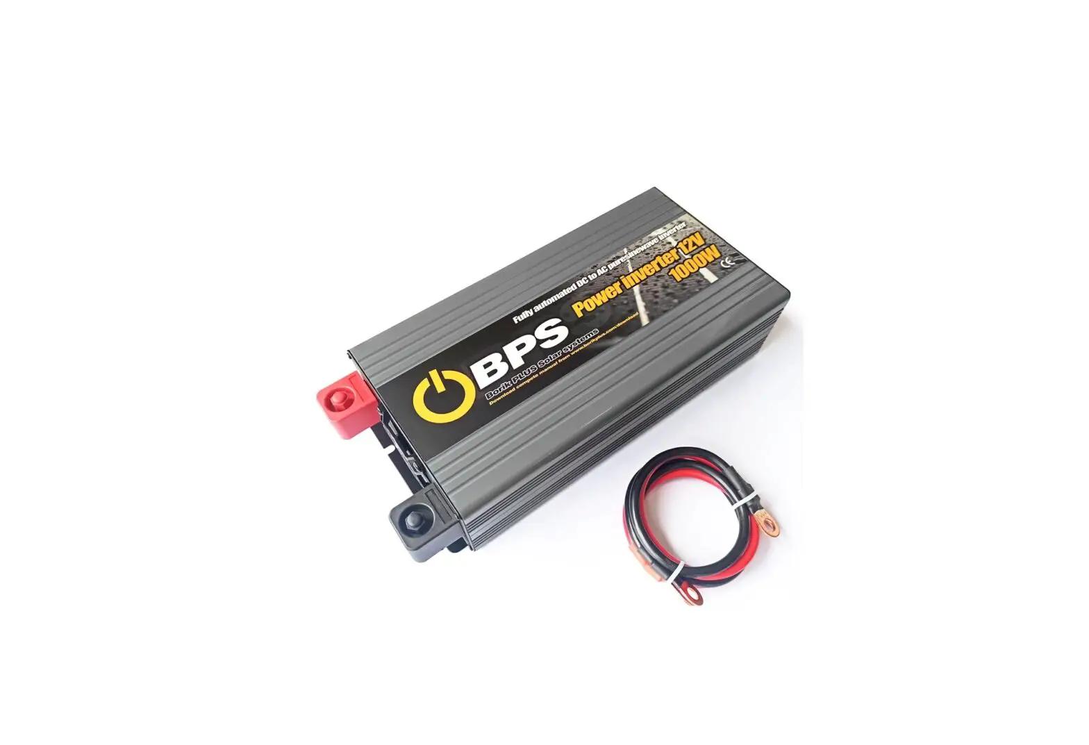
Borik Plus 1000W Pure Sine Wave Inverter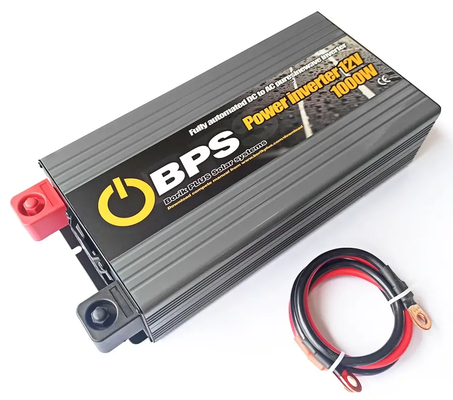
Safety Guidelines (Please read through this manual before assembling the power inverter)
- Risk of electrical shock and energy hazard. All failures should be examined by the qualified technician. Please do not remove the case oft he invcner by yourself.
- Please do not install the inverter in places with high moisture or near water.
- Please do not install the inverter in places with high ambient temperature. under direct sunlight or near flame source.
- Please only connect batteries with the same brand and model number in one battery bank. Using batteries from different manufacturers or different capacity is strictly prohibited.
- Never allow a spark or name in the vicinity oft he batteries because it may generate explosive gases during normal operation.
- Make sure the air flow from the fan is not obstructed at both sides (front and back) of the inverter. Please allow at least 15cm of space.
- Please do not s tact any object on the inverter.
![]() WARING: Batteries will have an aging problem after years of operation. It is suggested to execute regular battery maintenance (e.g. every year). Once aged. the batteries should be changed by professional technician. or the failed batteries may cause fire or other hazards.
WARING: Batteries will have an aging problem after years of operation. It is suggested to execute regular battery maintenance (e.g. every year). Once aged. the batteries should be changed by professional technician. or the failed batteries may cause fire or other hazards.
Pure Sine Wave Inverter
Pure Sine Wave Inverter Key Features
The Pure Sine Wave Inverter utilizes advanced high frequency switching technology in the power conversion process. The circuits arc similar to those used in power supplies for electronic equipment’s.
- Pure sine wave output (Tl ID<3%)
- Car Ignition Function
- Compliance to CE. FCC and E-Mark
- Low Voltage Protection (Three Stages Optional)
- High surge capability: for .. hard-to-start .. AC loads
- High efficiency up to 9 I%
- Power-Saving Mode
- 18 months global warranty
- Light weight: for easy installation
Inverter Function
When connected properly and the power switch is turned to the “O “. the inverter draws power from a battery and delivers a true sine wave AC output voltage. If the battery voltage is within the operating range of the unit, the inverter will continue to deliver AC power to the loads connected. High and lower bat1cry shutdowns will engage if the battery voltage falls out of the specified range of operation. ( I 0-15.5 VDC on 12V models. 20-31 VDC on 24 V models.)
Other Functions
| Power Saving Mode | SE | SEO | POWERSAVE mode OFF (factory set default) |
| SE1 | You would want 10 enable POWERSAVE mode if the inverter is only being used periodically to power loads. ll1is allows the inverter to draw less power from the batteries during non-use periods. The POWERSAVE mode will be activated when die output power is less than 15W When output power is more than 20W. die inverter will automatically return to normal status. | ||
| Buzzer Alarm | bu | bu0 | Turn off the buzzer. It only shows fault code arid the buzzer doesn’t alarm when the inverter has any fault |
| bu1 | The buzzer works normally. It shows fault code and the buzzer a forms when the inverter has any fault (factory set default) | ||
| Lo | LoO | Battery voltage is set1ed I0.SV ( I2V) / 2IV t24V} (factory set default) | |
| LU | Battery voltage is setted 10.8V (12/ / 21.6V (24V) | ||
| Lo2 | Battery voyage is cited I L3V (J 2V}/ 22.6V (24V) | ||
| pr | The inverter does not have this function. | ||
| Default | dF | Restore factory default settings | |
| Remarks: factory default setting is SE0, bu I , Lo0 and pr1. | |||
Operation Chart
If you want lo set the above functions. please sec the following chart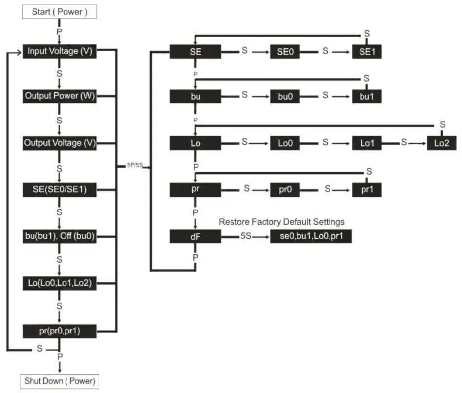
| Remarks: | |
| P | Press “Power” |
| 5P | Hold “Power” 5 seconds |
| S | Press “Select” |
| 5S | Hold “Select” 5 seconds |
| To program new settings | Select desired settings–hold “Select” 5 seconds—record & show next setting |
| Exit program mode | Release “Power” and “Select” 5 seconds. |
| For example: The unit is factory default set to Power-Saving Mode “OFF”. If you want this function to be “ON”, follow these steps: 1. Press “Power” to start the inverter; 2. Press “Power” and “Select” for 5seconds, enter into the main menu; 3. Press “Power” and choose the “SE” when the display shows the “SE”: 4. Press “Select” and choose “SEI”: 5. Press “Select” for 5seconds, the Power-Saving Mode is ON and the display will show the next function. | |
Main Specification of I000W and 1500W Pure Sine Inverter
| Model | YX-IKS- 1 -I I | YX-IKS-2.1 | YX-IKS-1-2 I | YX-IKS-2-2 | YX-1.5KS-1-1IYX-1.5KS-2-1 | YX-1.5KS-1-21 | YX-1.5KS-2-2 | |
| Continuous Power | 1000W | 1500W | ||||||
| Peak Power | 2000W | 2900W | ||||||
| DC Voltage | DC12V I | DC24V | DC12V 1 | DC24V | DCl2V I | DC24V | DCl2V | DC24 \ |
| AC Voltage | 100Vkf ((DOM or 120VAC r3V | 220VAC or 230VAC or 240VAC *3 1 | 1 iVAC 0-110VAC et 120VACr3V | 220VAC or.131)VAC ra4OVAC ±3V | ||||
| No Load Current Draws | 1 A | I 0.5A | IA | I 0.5A | 1 A | I 0.5A | I A | I 0.5A |
| Max AC Output Current | 8.5A | 4.5:\ | 13 6A | 6.8A | ||||
| DC Voltage Range | I0-15.5V | 20-31V | I 0-15.5V | 20-31V | ||||
| Low Voltage Alarm | LoO: I0.5V | IIW-0.3V | Lo0:21V | 22W-0.3V | Lo0:10.5V | IIV:1-1.13V | Lo0:21V | 22W0.3V |
| Lol: I0.8V | 11.3W0.3V | Lo1:21.6V | 22.6W-0.3V | Lo I :10.8V | 11.3W0.3V | Lo1:21.6V | 22.6W0.3V | |
| Lo2:11.3V | 11.8W0.3V | Lo2:22.6V | 23.6W-0.3V | Lo2:1I .3V | 11.8W-0.3V | Lo2:22.6V | 23.6W0.3V | |
| Low Voltage Shut Down | LoO: I0.5V | 10.5W-0.3V | Lo0:2 I V | 21W0.3V | Lo0:10.5V | 10.5V-10.3V | Lo0:21V | 21W-0.3V |
| Lol: I0.8V | 10.8W0.3V | Lo1:21.6V | 21.6W-0.3V | Lo I : I0.8V | 10.8W0.3V | Lo1:21.6V | 21.6\110.3 \ | |
| Lo2:11.3V | I I .3W-0.3V | Lo2:22.6V | 22.6W-0.3V | Lo2:I I .3V | 11.3W-0.3V | Lo2:22.6V | 22.6W-0.3 \ | |
| Low Voltage Alarm Recovery | LoO: I0.5V | 11.3V±0.3V | Lo0:21V | 22.6W-0.3V | Lo0:10.5V | I I .3W0.3V | Lo0:21V | 22.6W-0.3\ |
| Lo1:10.8V | 11.6W0.3V | Lo1:21.6V | 23.2W-0.3V | Lo1:10.8V | II.6W-0.3V | Lo I :2I.6V | 23.2W-0.3% | |
| l.o2:11.3V | 12.IW-0.3V | Lo2:22.6V | 24.2W-0.3V | Lo2:11.3V | I 2.1V:.4.3.3V | Lo2:22.6V | 24.2W-0.3V | |
| Low Voltage Protection Recovery | LoO: I0.5V | 12W0.3V | Lo0:21V | 24W0.3V | LoO: I0.5V | 12W-0.3V | Lo0:21V | 24Vs0.3V |
| Lo I : I0.8V | 12.3W0.3V | Lo I :21.6V | 24.6W-0.3V | Lo1:10.8V | 12.3W0.3V | Lo I :2I.6V | 24.6V30.3V | |
| Lo2:11.3V | 12.8W-0.3V | Lo2:22.6V | 25.6W-0.3V | Lo2:11.3V | 12.8W-0.3V | Lo2:22.6V | 25.6V30.3V | |
| Over Voltage Shut Down | 15.7W0.3V | 31.5W-0.3V | 15.7W-0.3V | 31.5V±0.3V | ||||
| Over Voltage Recovery | 15 win 3%. | 29.5W-0.3V | 15.3W-0.3V | 29.5W-0.3V | ||||
| Frequency | 5011z± 0.511z or (Oliz± 0.511z | |||||||
| Output Waveform | Pure Sine Wave | |||||||
| AC Regulation | THD<3% (Linear load) | |||||||
| Output Efficiency | up to 91% | |||
| Remote Control (Optional) | Cable length: 15m is available. | |||
| Ignition Function | Connect vehicles battery (or connect positive pole of vehicles’ STARTER). The inverters start simultaneously \\ ‘hen the vehicles start; The inverters % ill also shut down when the vehicles shut down. | |||
| Pt.,icction I unction | Low voltage alarm | code: F05 | Buzzer sounds and fault light turns red | |
| Low voltage shutdown | code: FOI | Recover by hand after the inverter shutdown. (The inverter will auto recover when the battery voltage go back to a normal level within 20ms.) | ||
| Over input voltage protection | code: F02 | Recover by hand after the inverter shutdown. (The inverter will auto recover when the battery voltage go back to a normal level within 20ms.) | ||
| Over load alarm | code: F06 | Buzzer sounds and fault light turns red when output power is overloaded around 110%. But the BUZZ and F06 code will not occured when the output power drop to a normal level within 20ms. | ||
| Over load protection | code: F03 | The inverter shutdown when output power is overlo; ‘tie,’ around 120%, it needs to be recovered by hand. | ||
| Over temperature alarm | code: F07 | Buzzer sounds and fault light turns red when the inverter’s internal temperature is higher than the limit value (90±5°C). | ||
| Over temperature protection | code: F04 | The inverter will automatically return to normal status when the internal temperature drops to 80±5°C. | ||
| Short circuit protection | code: F03 | Recover by hand | ||
| Reverse polarity protection | Built-in fuse | |||
| Fuse | Internal | USB port | 5V, 2.1 A | |
| Working Temperature | -10°C–+50°C | Product Size | 330x150x78mm | |
| Storage Temperature | -30°C–+70°C | Cooling Way | Intelligent cooling fan | |
| Start | Bipolar soft-start | Certification | CE, FCC and E-mark | |
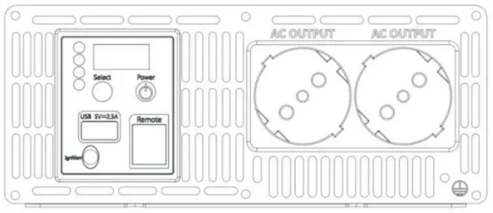
The Front Panel of 1000W and 1S00W Pure Sine Inverter
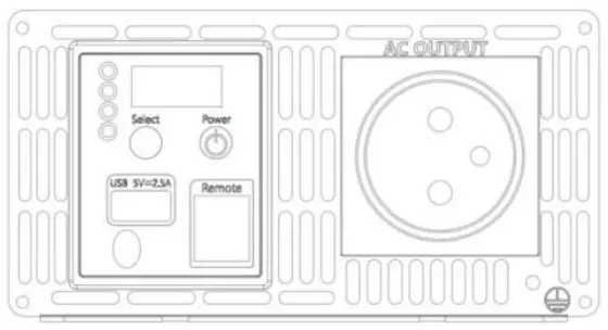 | |||
| Power | ON or OFF | ||
| Select | Select functions | ||
| LED Lights | status | Inv erter | Yellow light |
| Fault | Red light | ||
| DC-V | Show battery voltage | The battery low voltage protection has three levels, it can be setted by manual. (12v: Lo0 10.5v; Lol 10.8v; Lo2 11.3v / 24V: Lo0 21v; Lol 21.6v; Lo2 22.6v) | |
| AC-P | Show output power | The output power in the digital display will have ±2% errors. 1000W will show 1.00. | |
| AC-V | Show output voltage | The output voltage in the digital display will have ±3V errors. | |
| AC OUTPUT | For application demands of different geographic areas all over the world, there are many different kinds of optional AC outlets to choose from. | ||
The Rear Panel of I 0ti0W and 1 500W Pure Sine Inverter
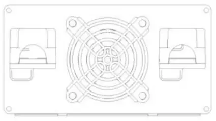 | |
| DC battery terminals | Connect the inverter to batteries or other power sources. Negative (-) and positive (*) DC terminals should be kept insulated to protect from accidental short |
| Cooling fan | Temperature and load controlled. |
Main Specification of 2000W and 2500W Pure Sine Inverter
| Model | YX-20-1-1 | I YX-2KS-2- I | I YX-2KS- I -2 | I YX-2KS-2-2 | YX-2.5KS- I-II | YX-2.5KS-2- 1 | I YX-2.5KS-1-2IYX-2.5KS-2-2 | |
| Continuous Power | 2000W | 2500W | ||||||
| Peak Power | 4000W | 4900W | ||||||
| DC Voltage | DCl2V | I DC24V | DC12V | I DC24V | DC12V | DC24V | DCl2V | I DC24V |
| AC Voltage | 1 oVAC or 110VAC or 120VAC – ” | .: I‘AC or230VAC or 240VAC 1 3V | 100VAC or I IOVAC or 120VAC ± 3V | 220VACor 230VACor 240VAC +.3V | ||||
| No Load Current Dra%%. | 1 A | I 0.5A | IA | I 0.5A | IA | I 0.5A | I:\ | (1 . %, |
| Max AC Output Current | I 6.7A | 8.7A | 20.8A | I0 s:\ | ||||
| DC Voltage Range | 10- 1 5.5V | 20-31V | 10-15.5V | 20-31 V | ||||
| Low Voltage Alarm | I.o0:10.5V | IIV-..1/40.3V | Lo0:2 1 V | 22V1-0.3V | I o0:10.5V | 11V±0.3V | Lo0:2 1 V | 22V±-0.3V |
| Lo I :10.8V | 11.3V±0.3V | Lol :2I.6V | 22.6V±-0.3V | Lo I : I0.8V | 11.3V±-0.3V | Lo1:21.6V | 22.6V±0.3V | |
| Lo2: I I.3V | 11.81/±0.3V | Lo2:22.6V | 23.6V±0.3V | Lo2:11.3V | 11.8W0.3V | Lo2:22.6V | 23.6V±0.3V | |
| Low Voltage Shut Down | LoO:I0.5V | 10.5V±0.3V | Lo0:21V | 21V+0.3V | LoO:I0.5V | I 0.5V±0.3V | Lo0:21V | 21V±0.3V |
| Lo I : I0.8V | I0.8V±0.3V | Lo1:21.6V | 21.6V±-0.3V | Lo I : I0.8V | 10.8V±-0.3V | Lo1:21.6V | 21.6V±-0.3V | |
| Lo2:1I.3V | 11.3V:.H.3.3V | Lo2:22.6V | 22.6V±0.3V | Lo2: I I.3V | 1 1.3V±0.3V | Lo2:22.6V | 22.6V1-0.3V | |
| Low Voltage Alarm Recovery | LoO: I0.5V | 11.3V±-0.3V | Lo0:2 I V | 22.6V±0.3V | LoO:I0.5V | 1 1.3V±0.3V | Lo0:2 I V | 22.6V±0.3V |
| I. 01:10.8V | 11.6V±-0.3V | Lol :21.6V | 23.2 W.0.3V | Lo1:10.8V | 11.6V±0.3V | Lo1:21.6V | 23.2V*0.3V | |
| 1.u2:11.3V | 12.1V±0.3V | Lo2:22.6V | 24.2V±0.3V | Lo2: I I.3V | 12.1V10.3V | Lo2:22.6V | 24.2)/±0.3 \ | |
| Low Voltage Protection Recovery | Lo0:10.5V | 12V-±0.3V | Lo0:21V | 24V±0.3V | LoO:I0.5V | 12V±-0.3V | Lo0:21V | 24V±0.3V |
| I .ol: I0.8V | 12.3VI-0.3V | Lo1:21.6V | 24.6V±0.3V | Lo I : I0.8V | 12.3V1-0.3V | Lo1:21.6V | 24.6V±0.3 \ | |
| Lo2:11.3V | 12.8V±0.3V | Lo2:22.6V | 25.6V±0.3V | Lo2:11.3V | 12.8V±-0.3V | Lo2:22.6V | 25.6V±0.3\ | |
| Over Voltage Shut Down | 15.7V*0.3V | 31.5V±0.3V | 15.7V*0.3V | 31.5V±0.3V | ||||
| Over Voltage Recovery | I5.3V±0.3V | 29.5V±0.3V | 15.3V±0.3V | 29.5V+0.3V | ||||
| Frequency | 50Hz t 0.5Hz or 6011z f 0.5Hz | |||||||
| Output Waveform | Pure Sinc Wave | |||||||
| AC Regulation | THD<3% (Linear load) | |||||||
| Output Efficiency | up to 91% | |||
| Remote Control (Optional) | Cable length: 15m is available. | |||
| Ignition Function | Connect vehicles battery (or connect positive pole of vehicles’ STARTER). The inverters start simultaneousl> When the vehicles start; The inverters will also shut down when the vehicles shut down. | |||
| Protection Function | Low voltage alarm | code: F05 | Buzzer sounds and fault light turns red | |
| Low voltage shutdown | code: F01 | Recover by hand after the inverter shutdown. (The inverter will auto recover when the battery voltage go back to a normal level within 20ms.) | ||
| Over input voltage protection | code: F02 | Recover by hand after the inverter shutdown. (The inverter will auto recover when the battery voltage go back to a normal level within 20ms.) | ||
| Over load alarm | code: F06 | Buzzer sounds and fault light turns red when output power is overloaded around 110%. But the BUZZ and F06 code will not occured when the output power drop to a normal level within 20ms. | ||
| Over load protection | code: F03 | The inverter shutdown when output power is overloaded around 120%. it needs to be recovered by hand. | ||
| Over temperature alarm | code: F07 | Buzzer sounds and fault light turns red when the inverter’s internal temperature is higher than the limit value (90-15°C). | ||
| Over temperature protection | code: F04 | The inverter will automatically return to normal status when the internal temperature drops to 80±5°C. | ||
| code: F08 | The indicator will show the code F08 when the thermostats in the inverters are broken. | |||
| Short circuit protection | code: F03 | Recover by hand | ||
| Reverse polarity protection | Built-in fuse | |||
| Fuse | Internal | USB port | 5V, 2.IA | |
| Working Temperature | -10°C–+50°C | Product Site | 35Ix197x82mm | |
| Storage Temperature | -30°C–+70°C | Cooling Way | Intelligent cooling fan | |
| Start | Bipolar soft-start | Certification | CE, FCC and E-mark | |
Main Specification of 3000W and 4000W Pure Sine Inverter
| Model | YX-3KS-1-1 | I YX-3KS-2- I I | YX-3KS-I.21 | YX-3KS-2.2 | YX-4KS-I-1 I | YX-4KS-2-I I | YX-4KS-I-2 i | YX-4KS-2-2 |
| Continuous Power | 3000W | 4000W | ||||||
| Peak Power | 6000W | 8000W | ||||||
| DC Voltage | DCl2V | I DC24V | DC12V | 1 DC24V | DC12V | I DC24V | DCl2V | I DC24V |
| AC Voltage | 100VW orlIONACa.120YAC r % | :AK or BO \ AC or240VAC ± 3V | 1COVAC or 110VAC or 120VAC:: 3V | 220VAC arBOVAC or240VAC r. 3 \ | ||||
| No Load Current Draws | 0.5A | I 2A | I 0.5A | I 2A | I 0 5 A | 1 2 A | I 0.5A | |
| Max AC Output Current | ‘ • \ | Il A | 1– \ | 18A | ||||
| DC Voltage Range | 10-15.5V | 20-3 1 V | 10-15.5V | 20–31V | ||||
| Low Voltage Alarm | Lo0:10.5V | I I V±0.3V | Lo0:21V | 22W0.3V | I.00:10.5V | 11V±0.3V | Lo0:21V | 22V±0.3V |
| I.o1:10.8V | 11.3W0.3V | Lo I :21.6V | 22.6W-0.3V | Lo I : I0.8V | 11.3W-0.3V | Lo I :21.6V | 22.6V±0.3V | |
| l_o2: I I.3V | I 1.8V±0.3V | Lo2:22.6V | 23.6W-0.3V | Lo2: I I.3V | I I .8V±0.3V | Lo2:22.6V | 23.6W-0.3V | |
| Low Voltage Shut Down | Lo0:10.5V | 10.5V±0.3V | Lo0:21V | 21V±0.3V | Lo0:10.5V | 10.5V±0.3V | Lo0:21V | 21V±0.3V |
| Lo I : I0.8V | I 0.8V±0.3V | Lo1:21.6V | 21.6V±0.3V | Lol: I 0.8V | 10.8V±0.3V | Lo1:21.6V | 21.6V±0.3V | |
| Lo2: I I.3V | 11.3V±0.3V | Lo2:22.6V | 22.6V±0.3V | Lo2:1I.3V | 11.3V±0.3V | Lo2:22.6V | 22.6V±0.3V | |
| Low Voltage Alarm Recovery | Lo0:10.5V | 11.3V±0.3V | Lo0:2 1 V | 22.6V±0.3V | LoO:I0.5V | 11.3V±0.3V | Lo0:2 I V | 22.6W-0.3V |
| Lo I : I0.8V | 11.6V±0.3V | Lo I :21.6V | 23.2W-0.3V | Lo I :10.8V | I 1.6V±0.3V | Lo1:21.6V | 23.2V±0.3V | |
| Lo2: I I.3V | I 2.1V±0.3V | Lo2:22.6V | 24.2V±0.3V | Lo2: I I .3V | 12.IV±0.3V | Lo2:22.6V | 24.2V±0.3\‘ | |
| Low Voltage Protection Recovery | LoO:I0.5V | 1 2V+.0.3V | Lo0:21V | 24W-0.3V | LoO:I0.5V | I2V±0.3V | Lo0:21V | 24V±0.3 \ |
| Lo I :10.8V | 12.3V±0.3V | Lo I :21.6V | 24.6V±0.3V | Lo I : I 0.8V | 12.3V±0.3V | Lo1:21.6V | 24.6V±0.3V | |
| Lo2: I I.3V | 12.8V±0.3V | Lo2:22.6V | 25.6V±0.3V | Lo2: I I.3V | 12.8V±0.3V | Lo2:22.6V | 25.6W0.3V | |
| Over Voltage Shut Down | 15.7V*0.3V | 31.5V±0.3V | 15.7V±0.3V | 31.5V±0.3V | ||||
| Over Voltage Recovery | 15.3V±0.3V | 29.5V±0.3V | 15.3V±0.3V | 29.5V±0.3V | ||||
| Frequency | 50Hz ± 0.511z or 601Iz ± 0.5Hz | |||||||
| Output Waveform | Pure Sine Wave | |||||||
| AC Regulation | THD<3% (Linear load) | |||||||
| Output Efficiency | up to 91% | |||
| Remote Control (Optional) | Cable length: 15m is available. | |||
| Ignition Function | Connect vehicles battery (or connect positive pole of vehicles’ STARTER). The inverters start simultaneothl■ When the vehicles start; The inverters will also shut down when the vehicles shut down. | |||
| Pi otectitni Function | Low voltage alarm | code: F05 | Buzzer sounds and fault light turns red | |
| Low voltage shutdown | code: F01 | Recover by hand after the inverter shutdown. (The inverter will auto recover when the battery voltage go back to a normal level within 20ms.) | ||
| Over input voltage protection | code: F02 | Recover by hand after the inverter shutdown. (The inverter will auto recover when the battery voltage go back to a normal level within 20ms.) | ||
| Over load alarm | code: F06 | Butter sounds and fault light turns red when output power is overloaded around 110%. But the BUZZ and F06 code will not occured when the output power drop to a normal level within 20ms. | ||
| Over load protection | code: F03 | The inverter shutdown when output power is overloaded around 120%. it needs to be recovered by hand. | ||
| Over temperature alarm | code: F07 | Buzzer sounds and fault light turns red when the inverter’s internal temperature is higher than the limit value (90-15°C). | ||
| Over temperature protection | code: F04 | The inverter will automatically return to normal status when the internal temperature drops to 80-t5c’t | ||
| c ode: FOS „ | The indicator will show the code F08 when the thermostats in the inverters are broken. | |||
| Short circuit protection | code: PO? | Recover by hand | ||
| Reverse polarity protection | Built-in fuse | |||
| Fuse | Internal | USB port | 5V, 2.1A | |
| Working Temperature | -10°C–+50°C | Product Size | 436x I 97x82mm | |
| Storage Temperature | -30°C–+70°C | Cooling Way | Intelligent cooling fan | |
| Start | Bipolar soft-stan | Certification | CE. FCC and E-mark | |
The Front Panel of 2000W, 2500W, 3tl0tl W and 4000W Pure Sine Inverter
 | |||
| Power | ON or OFF | ||
| Select | Select functions | ||
| LED Lights | status | Imerter | Yellow light |
| Fault | Red light | ||
| DC-V | Show battery voltage | The battery low voltage protection has three levels, it can be setted by manual. (12v: Lo0 10.5v: Lol 10.8v; Lo2 11.3v / 24V: Lo0 21v; Lol 21.6v; Lo2 22.6v) | |
| AC-P | Show output power | The output power in the digital display will have ±2% errors. 1000W will show 1.00. | |
| AC-V | Show output voltage | The output voltage in the digital display will have ±3V errors. | |
| AC OUTPUT | For application deman Is of different geographic areas all over the world, there are many different kinds of optional AC outlets to choose from. | ||
The Rear Panel of 2000W, 2500W, 3ll00W and 4000W Pure Sine Inverter
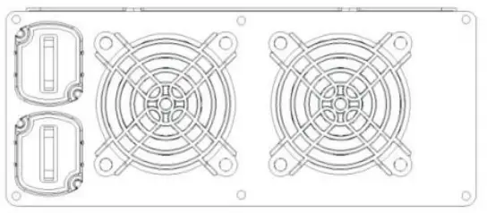 | |
| DC battery terminals
| Connect the inverter to batteries or other power sources. Negative (-) and positive (+) DC terminals should be kept insulated to protect from accidental short circuits. |
| Cooling fan | Temperature and load controlled. |
Installation & Wiring
Wiring for Batteries: Wire connections should be as short as possible and less than 1.5 meter is highly recommended. Long DC wires tend to lose efficiency and reduce the overall performances of an inverter. Make sure that suitable wires arc chosen based on the rating of current. Too small of a cross-section will result in overheating that could induce certain danger. Please refer to Table 4-1.
Note: Please consult our local distributors if you have any questions.
| Rated Current of Equipment (amp) | Cross-section of Lead (mm2) | AWG Suggested Wiring | |
| 16A-25A | 2.5 | 12 | Safety Wiring Range |
| 25A-32A | 4 | 10 | |
| 32A-40A | 6 | 8 | |
| 40A-60A | 10 | 6 | |
| 63A-80A | 16 | 4 | |
| 80A-100A | 25 | 2 | |
| 100A-125A | 35 | 1 | |
| 125A | 50 | 0 |
Table 4- I Suggestion for Wire Selection
To make DC wiring connections:
![]() CAUTION Clean battery terminals before making connections. Wear eye protection to keep corrosion from coming in contact with eyes.
CAUTION Clean battery terminals before making connections. Wear eye protection to keep corrosion from coming in contact with eyes.
Connect the DC POSITIVE cable to the POSITIVE ( + ) terminal on the battery. Next. connect the cable to the POSITIVE terninal (red plastic cover) on the inverter. Connect the DC NEGATIVE cable to the NEGATIVE ( – ) terminal on the battery. Next. connect the cable to the NEGATIVE terminal ( black plastic cover) on the inverter. Observe the polarities carefully while performing the installation and do not reverse the polarities. And make sure all the DC connections arc tight. Loose connections will ovcrhca1 and could result in a potential fire hazard.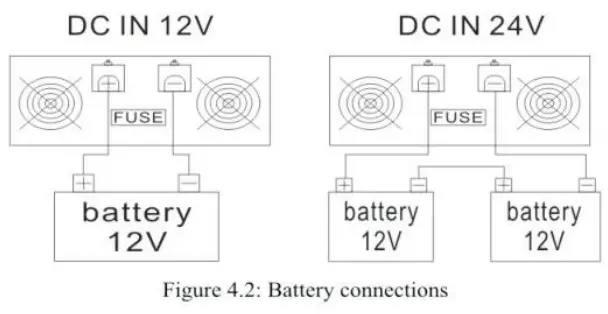
Requirement of Installation
The unit should be mounted on a flat surface or holding rack with suitable strenth. In order to ensure the lifespan of the unit, please refrain from operating in environment of high dust. high temperature or high moisture. This is a power supply with built-in DC fan. Please make sure that ventilation is not blocked.
(Note: There should be no barriers wi1hin 15cm of the ventilating holes.)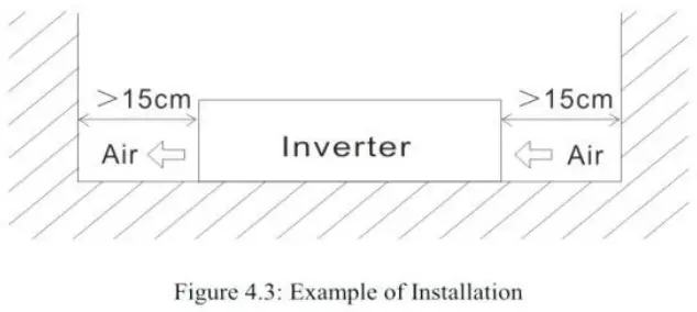
Mounting Suggestion:
There arc 4 semi-circular cutout on the side flanges of the inverter. It can be used for fixing inverter onto the system enclosure. We high recommend mounting is the horizontal position. Please make sure ventilation openings arc free from obstruction.
Fault Conditions and Indicators
The following fault conditions arc displayed on the control panel along with an alarm sound and a red light.
| Control Panel Indication | Fault Condition | Solution |
| HIGH BATT SHUTDOWN (code: F02) | Battery voltage too high | Check for fault with battery charging system. Manually reset inverter by pressing switch “POWER” |
| LOW BAIT SHUTDOWN (code: FOI) | Battery voltage too low | Charge battery. Manually reset inverter by pressing switch “Power” |
| OVERLOAD SHUTDOWN (code: F03) | Battery current too high, probable AC overload | Reduce load on inverter. |
| OVERTEMP SHUTDOWN (Code: F04) | System over-temperature | Improve ventilation and cooling and/or reduce load on inverter. |
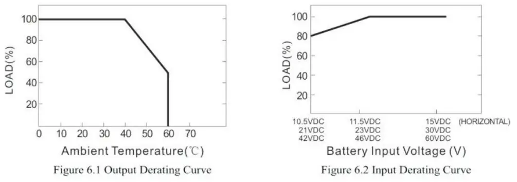
Derating
![]() Notes on output load:
Notes on output load:
The inverter can power most of equipment’s that need an AC source which can provide inverter continuously. But for
certain load type, the unit may not work properly.
- Since inductive 1oads or motor based equipment’s need a large start up current (6- 10 times of its rated current). the inverter may not start up successfully with these kinds of load.
- When the output arc capacitive or rectified equipment’s (such as switching power supply). it is suggested 10 operate these equipment at no load or light load. To ensure proper operation, you should increase the load only after the inverter has started up.

Warranty
18 mon1hs of g lobal warranty is provided for inverter under normal operating conditions. Please do no t change components or modify the unit by yourself. otherwise FACTORY may reserve the right not to provide the complete warranty.


