![]()
RZBoard V2L AI Accelerated Development Board
RZBoard V2L
Hardware User Guide
v1.0 October 05, 2022
Document Control
| Document Version: | 1.0 |
| Document Date: | 10/5/2022 |
| Document Author: | Peter Fenn |
| Document Classification: | Public |
| Document Distribution: | Public |
Version History
| Version | Date | Comment |
| 1.0 | 10/5/2022 | Initial public release (Rev 1.2 production PCB) |
Hardware Checklist
Hardware items recommended for application development are the following
| # | Item Description |
| 1 | Computer (Windows / Linux / Mac) with installed development tools (see below) |
| 2 | Avnet RZBoard V2L board |
| 3 | USB to Serial Cable (or use of VCOM interface from debugger probe) |
| 4 | 1x fly-lead (to select SCIF download boot mode) |
| 5 | Segger J-LINK debugger (or other debugger from the subset supported) |
| 6 | 5V 2A power adapter (plus USB type-A to USB-C cable) |
| 7 | USB current monitor dongle (optional) |
| 8 | MaaXBoard MIPI-DSI 7” capacitive-touch 720 x 1280 display (optional) p/n: AES-ACC-MAAX-DISP1 |
| 9 | MaaXBoard MIPI-CSI Camera, 5 MP, OV5640 image sensor (optional) p/n: AES-ACC-MAAX-CAM1 |
Table 1 – Hardware Checklist
Software Checklist
Listed below are software items mentioned in this document
| # | Item Description | |
| 1 | Renesas E2 Studio IDE (version 2022-07 or later) | https://www.renesas.com/us/en/software-tool/e-studio |
| 2 | teraterm-4.106.exe | Use for console communication and SCIF download mode |
| 3 | flashwriter_RZBoard.mot | FlashWriter tool. Use to flash SREC images into eMMC or QSPI |
| 4 | bl2_bp-RZBoard.srec | BL2 bootloader SREC image, ARM TFA (Trusted Firmware-A) |
| 5 | fip-RZBoard.srec | BL31 and uboot combined bootloader SREC image (ARM TFA) |
| 6 | core-image-RZBoard- 20220920085823.rootfs.wic | Linux kernel images & root filesystem (Linux system image, write this to to eMMC or SD card) |
| 7 | https://github.com/Avnet/RZBoard | Linux kernel source |
Table 2 – Software Checklist
Introduction
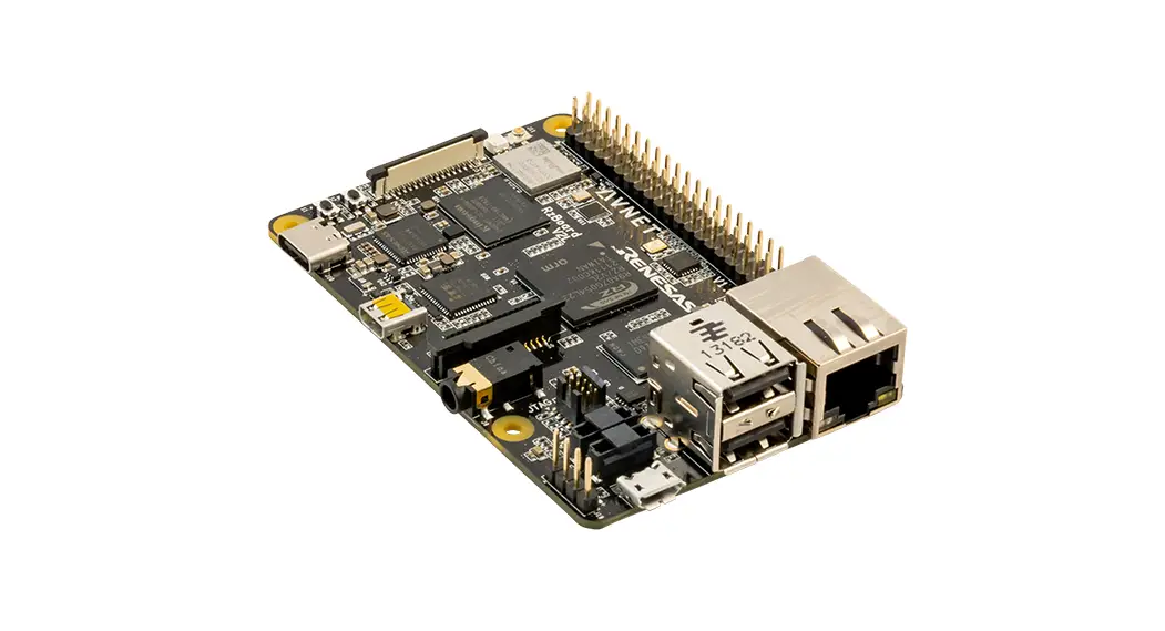
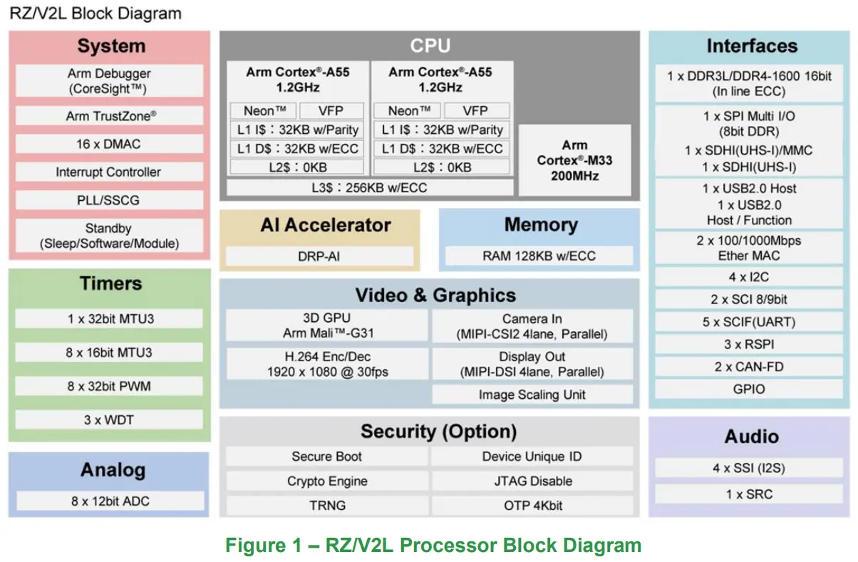
RZBoard V2L is a power efficient, vision-AI accelerated development board in a popular single board computer format with well supported expansion interfaces. Based on the Renesas RZ/V2L processor, this platform is ideal for development of cost-efficient vision-AI and a range of energy-efficient edge AI applications. It’s RZ/V2L processor has two 1.2GHz Arm® Cortex®-A55 cores plus a 200MHz Cortex-M33 core, a MALI 3D GPU and Image Scaling Unit. This processor SoC further differentiates itself with an onchip DRP-AI accelerator plus H.264 video (1920 x 1080) encode/decode function, making it ideal for implementing cost-effective embedded-vision applications.
RZBoard V2L is engineered in a compact Raspberry Pi form-factor with a versatile set of expansion interfaces, including Gigabit Ethernet, 801.11ac Wi-Fi and Bluetooth 5, two USB 2.0 hosts and a USB 2.0 OTG interface, MIPI DSI and CSI camera interfaces, CANFD interface, Pi-HAT compatible 40-pin expansion header and Click Shuttle expansion header.
The board supports analog audio applications via it’s audio codec and stereo headphone jack. It also provides five 12bit ADC inputs for interfacing with analog sensors. 5V input power is sourced via a USB-C connector and managed via a single-chip Renesas RAA215300 PMIC device.
Onboard memory includes 2GB DDR4, 32GB eMMC and 16MB QSPI flash memory, plus microSD slot for removable media.
Software enablement includes CIP Kernel based Linux BSP (maintained for 10 years+) plus reference designs that highlight efficient vision AI implementations using the DRP-AI core. Onboard 10-pin JTAG/SWD mini-header and 4-pin UART header enable the use of an external debugger and USB-serial cable.
Accessory options include a MIPI 7-inch display, MIPI CSI camera and 5V/3A USB Type C power supply.
5.1 RZBoard V2L Info
- Part# to order: AES-RZB-V2L-SK-G
- Product Page: https://avnet.me/RZBoard-V2L
5.2 Items Included with RZBoard V2L
- RZBoard V2L board
- QuickStart Card
- Downloadable examples, reference designs and documentation
5.3 Important Reference Documents
- RZBoard V2L QuickStart Card (QSC)
- RZBoard V2L Product Brief
- RZBoard V2L Hardware User Guide (this document)
- RZBoard V2L Linux Yocto User Manual
- RZBoard V2L Linux Yocto Development Guide
- RZBoard V2L Schematic and BOM (available under NDA)
- Renesas RZ/V2L Group User’s Manual: Hardware (r01uh0936ej0100-rzv2l.pdf
RZBoard V2L Architecture & Features
6.1 Features
Renesas RZ/V2L energy-efficient Vision-AI MPU with:
- RZ/V2L processor part number: R9A07G054L23GBG
- 2x Arm Cortex A55 (1.2 GHz)
- 1x Arm Cortex M33 (200 MHz)
- 1x Arm MALI G31 3D-GPU (500 MHz), plus Image Scaling Unit
- DRP-AI accelerator (1 TOPS/W class, capable of running Tiny YOLOv2 at 28fps)
- DRP Simple ISP machine-vision library functions (supports up to 1920 x 1080)
- H.264 Hardware Video Encode/Decode (1920 x 1080)
- 128KB ECC RAM
Avnet SBC development board in Raspberry-Pi / MaaXBoard form-factor includes:
- 2GB DDR4 (16-bit, single-channel, with in-line ECC)
- 16GB eMMC memory
- Micro SD removable storage
- 16MB QSPI NOR Flash
- 1G Ethernet wired network interface
- 801.11ac Wi-Fi wireless network interface and Bluetooth 5 interface
- U.FL connected external antenna
- 2x USB 2.0 Host and 1x OTG USB 2.0 interfaces
- CANFD interface (includes onboard CAN transceiver)
- MIPI DSI and HDMI display interfaces (selectable)
- MIPI-CSI camera interface
- 40-pin Pi-HAT compatible expansion header
- 16-pin MikroE Click Shuttle expansion header
- Renesas RAA215300 PMIC
- 8-pin WTB connector with 4x 12bit ADC inputs plus CAN-FD
- 8-pin WTB connector with UART and spare USB expansion CAN-FD
- 10-pin JTAG/SWD debugger header
- Audio Codec and audio jack stereo output and microphone input
- USB-Type C connector for 5V power input
- 1x User RGB LED, 1x power LED
- 2x button switches
6.2 Block Diagram – Renesas RZ/V2L Processor
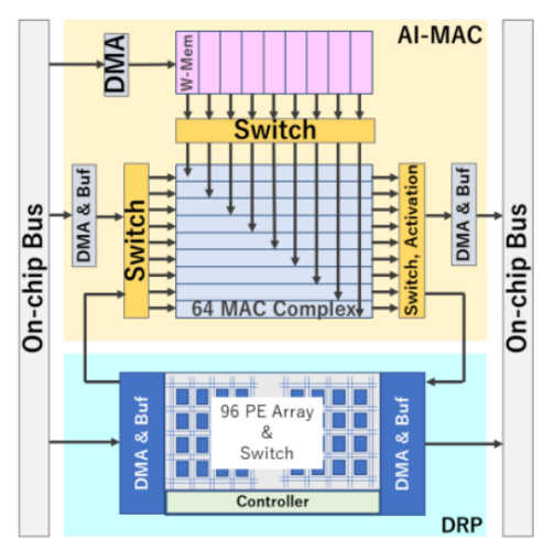
6.3 DRP-AI Accelerator Core
Dynamically Reconfigurable Processor (DRP) is a programmable, highly flexible accelerator core, optimised for use in AI accelerated vision applications
| DRP-AI Resource | Relevant Specs. | AI Operations Best Suited For |
| DRP | 192 ALU/DMU @ 266 MHz | Pooling, Softmax, + other processing |
| AI-MAC | 576 MAC @ 400 MHz | Convolution |
| Data type | FP16 | higher precision than INT8 (used by competitors) |
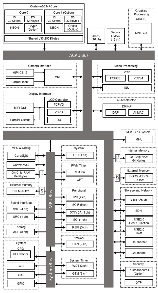
6.4 RZ/V2L Architecture (ACPU bus, MCPU bus, System bus)
6.5 RZBoard V2L Block Diagram
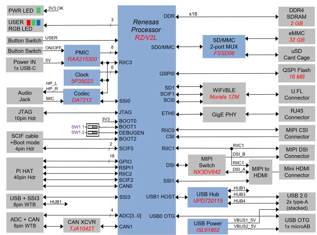
Figure 2 – RZBoard V2L Block Diagram (Rev 1.2 PCB)
Renesas parts on RZBoard (8 devices)
- RZ/V2L Processor
- RAA215300 PMIC
- 5P35023B Clock
- DA7212 Audio Codec
- UPD720115 USB Hub
- ISL61852 USB Power
- AT25QL128A QSPI NOR
- SLG7RN45292 Configurable Analog
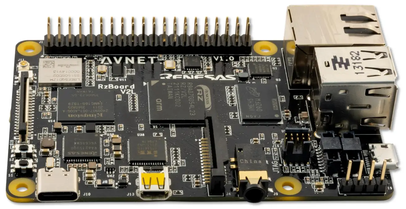
6.6 RZBoard V2L Component Locations (Top)
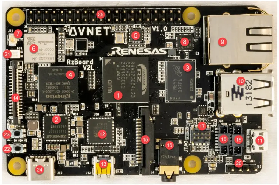
| # | Ref | Component Description | # | Ref | Component Description |
| 1 | U1 | Renesas RZ/V2L processor | 14 | J5 | MIPI DSI display connector |
| 2 | U39 | Renesas RAA215300 PMIC | 15 | J4 | MIPI CSI camera connector |
| 3 | U3 | LPDDR4 SDRAM memory | 16 | J9 | Stereo audio jack |
| 4 | U14 | eMMC memory (32G) | 17 | J16 | 10-pin header (JTAG/SWD) |
| 5 | U11 | QSPI NOR flash memory (16 MB) | 18 | J20 | 8-pin WTB connector (UART, USB) |
| 6 | U9 | Murata Wi-Fi/BT module | 19 | J18 | 8-pin WTB connector (ADC, CAN1) |
| 7 | J11 | U.FL antenna connector | 20 | J19 | 4-pin header (debug uart) |
| 8 | U7 | GMII Gigabit Ethernet PHY | 21 | D33 | User RGB LED |
| 9 | J7 | Gig Ethernet RJ45 connector | 22 | S1 | S1 button switch (ON/OFF) |
| 10 | J6 | Stacked USB host connectors | 23 | S2 | S2 button switch (USER) |
| 11 | J3 | OTG USB 2.0 connector | 24 | J10 | USB-C 5V power input |
| 12 | U38 | MIPI to HDMI display convertor | 25 | J1 | 40-pin Pi-HAT expansion header |
| 13 | J13 | Micro HDMI display connector |
Table 3 – Key Components on RZBoard V2L (Top)
6.7 RZBoard V2L BaseBoard Component Locations (Bottom)
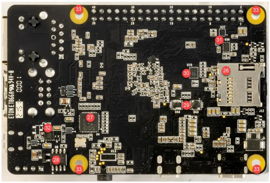
| # | Ref | Component Description | # | Ref | Component Description |
| 26 | J12 | MicroSD cage (removable storage) | 30 | U10 | eMMC / microSD QSPI bus switch |
| 27 | U4 | USB 4-port HUB | 31 | U36 U37 | 3V3 / 1V8 Greenpak level-shifter 3V3 / 1V8 level-shifter |
| 28 | U8 | CAN transceiver | 32 | U6 | USB OTG 5V switch |
| 29 | U43 U44 | MIPI / HDMI display switch | 33 | MH | Mounting Holes (standoffs or Pi-Hat) |
Table 4 – Key Components on RZBoard V2L (Bottom)
6.8 Debug Header, Switches and LEDs
6.8.1 Debug UART 4-pin Header (J19)
A USB-Serial debug cable needs to be attached to the J1 header for console debug output and Linux command-line access.
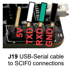
| J19 Pin | RZBoard V2L Signals | Serial Interface Signal Direction |
| 1 | BOOT2 | n/a |
| 2 | TXD | TX to RZBoard |
| 3 | RXD | RX from RZBoard |
| 4 | GND | GND |
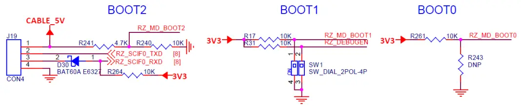
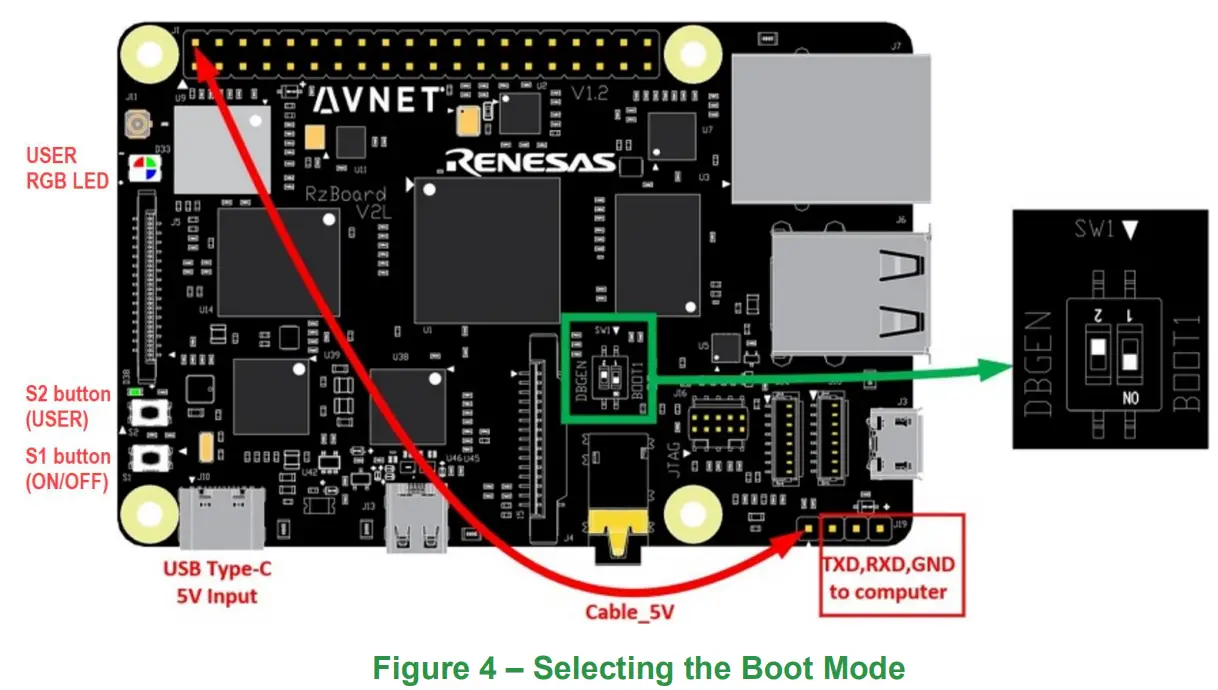
6.8.2 DIP Switches (SW1) and Boot-Mode Selection
| SW1 # | Function | |
| SW1.1 | BOOT1 | |
| SW1.2 | DEBUGEN |
RZ/V2L boot-mode is determined by the state of BOOT[2:0] at end of Reset:
- BOOT2 (Debug header J19 pin 1)
- BOOT1 (DIP switch SW1.1)
- BOOT0 (SD card inserted/or not)
RZBoard supports 4 different boot sources (default eMMC boot mode is highlighted):
| BOOT2 | BOOT1 | BOOT0 | BOOT MODE |
| 0 | 0 | 0 | Boot from 3V3 SD card |
| 0 | 0 | 1 | Boot from 1V8 eMMC (default) |
| 0 | 1 | 1 | Boot from 1V8 QSPI flash |
| 1 | 0 | 1 | Boot from SCIF serial download |
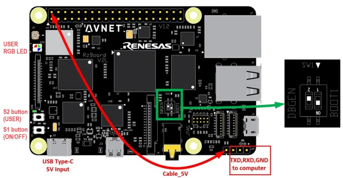
To use “SCIF serial download” boot mode:
– Remove SD card from SD card cage (this sets BOOT0=1)
– Strap a fly-lead from pin1 of this J19 debug header to J1-pin2 on 40pin header (ie. To 5V pin, this sets BOOT2=1)
o BOOT2 is set by use of a flywire from J19-pin1 of Debug UART 4pin header.
| BOOT2 | Strapping to change boot mode |
| 0 | Default. No flywire strapping required |
| 1 | Strap J19-pin1 to 5V (J1-pin2 on HAT 40pin header) |
o BOOT1 is set by DIP switch SW1.1
| BOOT1 | Strapping to change boot mode |
| 0 | Controlled by DIP switch: SW1.1 = ON |
| 1 | Controlled by DIP switch: SW1.1 = OFF |
o BOOT0 is driven by the SD card-detect signal (from uSD card cage)
| BOOT1 | Strapping to change boot mode |
| 0 | SD card is inserted |
| 1 | SD card not inserted |
6.8.3 Push-Button Switches
Two pushbuttons are located near the board edge, in the bottom-left corner
| Ref. Des | Switch Name | Button Switch Function | RZ/V2L GPIO Pin | PMIC Pin |
| S1 | ONOFF | Board ON/OFF control | n/a | PMIC PWRON input |
| S2 | USER | USER function (unassigned) | RZ_P39_0 | n/a |
6.8.4 Status LEDs
| Ref. Des. | LED Status Function | LED Color | RZ/V2L GPIO Pin | Linux sysfs Definitions | RZ/V2L Board Function |
| D38 | PWR | Green | n/a | n/a | 3V3 status |
| D33 | USER-RED | Red | RZ_P8_1 | /sys/class/leds/ledred | GPIO / PWM |
| D33 | USER-GREEN | Green | RZ_P17_2 | /sys/class/leds/ledbgreen | GPIO / PWM |
| D33 | USER-BLUE | Blue | RZ_P19_1 | /sys/class/leds/ledblue | GPIO / PWM |
The User RGB LED can easily be exercised from Linux command-line using sysfs commands: eg.
echo default-on > /sys/class/leds/ledblue/trigger
echo 0 > /sys/class/leds/ledblue/brightness
echo 1 > /sys/class/leds/ledgreen/brightness
echo 0 > /sys/class/leds/ledgreen/brightness
echo 1 > /sys/class/leds/ledred/brightness
echo 0 > /sys/class/leds/ledred/brightness
echo heartbeat > /sys/class/leds/ledblue/trigger
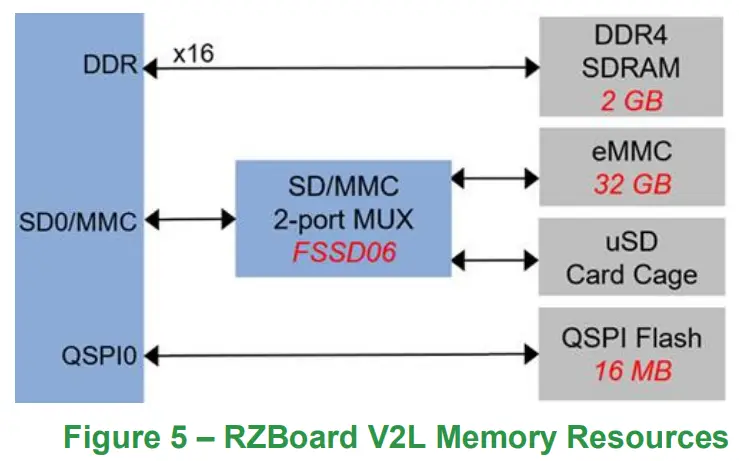
6.9 Memory Resources
RZBoard includes the following onboard memory resources:
| Memory Type | RZ/V2L Interface | Memory Size | Performance Considerations | Part Number |
| DDR4 SDRAM | DDR | 2 GB | 800 MHz, x16 bus | Micron MT40A1G16KD-062E |
| eMMC flash | SD0 | 32 GB | 200 MHz, x8 bus | Micron MTFC32GAZAQHD-IT |
| microSD slot | SD0 | removable media | ??? MHz, x4 bus | determined by User |
| QSPI flash | QSPI0 | 16 MB | 104 MHz, x4 bus | Adesto AT25QL128A-UIUE-T |
6.9.1 eMMC Memory (Partition size and Programming)
- For convenience, the procedures for changing partition size and programming new images into eMMC flash memory are included in the Appendix area of this User Guide document
- Configuring and programming the microSD card and QSPI memory use a similar scripted approach, but this is detailed in the software documentation
6.10 Peripheral Devices and Interfaces
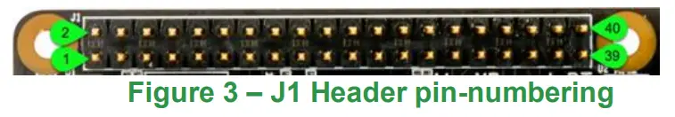
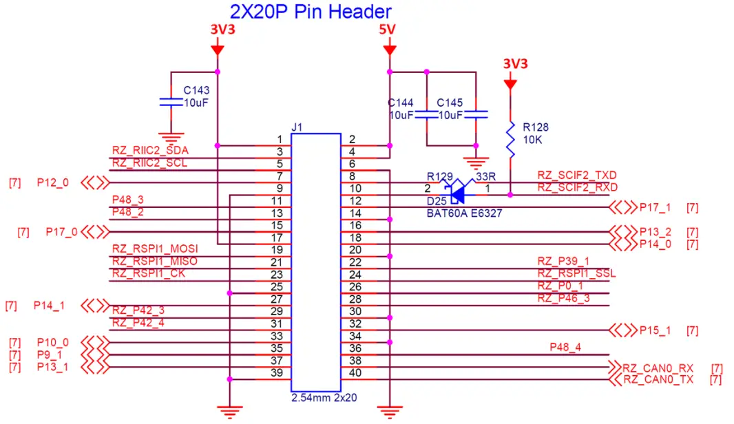
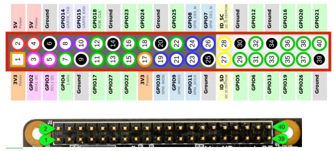
6.10.1 J1: Pi-HAT compatible 40-pin header
| Pin # | Possible HAT Pin Function | J1 RZBoard V2L Signal Name | Pin # | Possible HAT Pin Function | J1 RZBoard V2L Signal Name |
| 1 | 3V3 | VDD_3V3 | 2 | 5V | 5V_SYS |
| 3 | I2C_SDA | RZ_RIIC2_SDA | 4 | 5V | 5V_SYS |
| 5 | I2C_SCL | RZ_RIIC2_SCL | 6 | GND | GND |
| 7 | GPIO / GPCLK0 | P12_0 | 8 | UART_TX | RZ_SCIF2_TXD |
| 9 | GND | GND | 10 | UART_RX | RZ_SCIF2_RXD |
| 11 | GPIO / RTS | P48_3 | 12 | PCM_CLK | P17_1 |
| 13 | GPIO | P48_2 | 14 | GND | GND |
| 15 | GPIO | P17_0 | 16 | GPIO | P13_2 |
| 17 | 3V3 | VDD_3V3 | 18 | GPIO | P14_0 |
| 19 | SPI_MOSI | RZ_RSPI1_MOSI | 20 | GND | GND |
| 21 | SPI_MISO | RZ_RSPI1_MISO | 22 | GPIO | RZ_P39_1 |
| 23 | SPI_SCLK | RZ_RSPI1_CK | 24 | SPI_CS0 | RZ_RSPI1_SSL |
| 25 | GND | GND | 26 | SPI_CS1 | RZ_P0_1 |
| 27 | EEPROM_SDA | P14_1 | 28 | EEPROM_SCL | RZ_P46_3 |
| 29 | GPIO / GPCLK1 | RZ_P42_3 | 30 | GND | GND |
| 31 | GPIO / GPCLK2 | RZ_P42_4 | 32 | GPIO / PWM0 | P15_1 |
| 33 | GPIO / PWM1 | P10_0 | 34 | GND | GND |
| 35 | GPIO / PCM_FS | P9_1 | 36 | GPIO / CTS | P48_4 |
| 37 | GPIO | P13_1 | 38 | GPIO / PCM_DIN | RZ_CAN0_RX |
| 39 | GND | GND | 40 | GPIO / PCM_DOUT | RZ_CAN0_TX |
Table 5 – Pi-HAT compatible 40-pin header (J1)
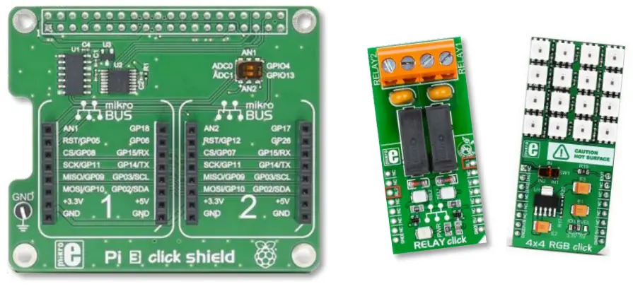
6.10.2 J1: Pinout Comparison with MikroE Pi-2-Click HAT Adapter
- Pinout for recommended HAT adapter ($8.00) is shown below (this accommodates two Click boards)
| Pin # | Pi-2-Click HAT Pin Function | J1 RZBoard V2L Signal Name | Pin # | Pi-2-Click HAT Pin Function | J1 RZBoard V2L Signal Name |
| 1 | 3V3 | VDD_3V3 | 2 | 5V | 5V_SYS |
| 3 | GPIO2 SDA | RZ_RIIC2_SDA | 4 | 5V | 5V_SYS |
| 5 | GPIO3 SCL | RZ_RIIC2_SCL | 6 | GND | GND |
| 7 | GPIO4 AN1 | P12_0 | 8 | GPIO14 UART_TX | RZ_SCIF2_TXD |
| 9 | GND | GND | 10 | GPIO15 UART_RX | RZ_SCIF2_RXD |
| 11 | GPIO17 PWM2 | P48_3 | 12 | GPIO18 PWM1 | P17_1 |
| 13 | GPIO27 nc | P48_2 | 14 | GND | GND |
| 15 | GPIO22 nc | P17_0 | 16 | GPIO23 nc | P13_2 |
| 17 | 3V3 | VDD_3V3 | 18 | GPIO24 nc | P14_0 |
| 19 | GPIO10 SPI_MOSI | RZ_RSPI1_MOSI | 20 | GND | GND |
| 21 | GPIO9 SPI_MISO | RZ_RSPI1_MISO | 22 | GPIO25 nc | RZ_P39_1 |
| 23 | GPIO11 SPI_SCLK | RZ_RSPI1_CK | 24 | GPIO8 SPI_CS0 | RZ_RSPI1_SSL |
| 25 | GND | GND | 26 | GPIO7 SPI_CS1 | RZ_P0_1 |
| 27 | ID_SDA nc | P14_1 | 28 | ID_SCL nc | RZ_P46_3 |
| 29 | GPIO5 RST1 | RZ_P42_3 | 30 | GND | GND |
| 31 | GPIO6 INT1 | RZ_P42_4 | 32 | GPIO12 nc | P15_1 |
| 33 | GPIO13 AN2 | P10_0 | 34 | GND | GND |
| 35 | GPIO19 RST2 | P9_1 | 36 | GPIO16 nc | P48_4 |
| 37 | GPIO26 INT2 | P13_1 | 38 | GPIO20 nc | RZ_CAN0_RX |
| 39 | GND | GND | 40 | GPIO21 nc | RZ_CAN0_TX |
Table 6 – MikroE Pi-2-Click HAT Adapter Mapping to J1 Header
6.10.3 MikroE Click Boards
- Over 1200+ Click boards available. Orderable from Avnet http://avnet.me/click
- Parametric search tool on MikroE website
- Open source library code available at https://www.mikroe.com/click-boards
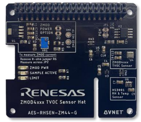
6.10.4 Pi HAT Expansion Boards
- Ecosystem of Pi HAT boards support a wide range of functionality
- See listings at websites such as https://pinout.xyz/boards
- Height of stacked boards is minimized as RZ/V2L does not require heatsink
6.10.5 J16: SWD/JTAG debugger 10-pin mini-header
The 10-pin Mini-header by default supports the SWD interface tabled below
| JTAG | SWD | Pin | Pin | SWD | JTAG |
| JTAG_TMS_18 | SWD_IO | 2 | 1 | IF_VREF | 1V8 |
| JTAG_TCK_18 | SWCLK | 4 | 3 | GND | GND |
| JTAG_TDO_18 | SWO | 6 | 5 | GND | GND |
| JTAG_TDI_18 | IF_TDI | 8 | 7 | IF_ISPEN | N/C |
| RZ_PRST# | IF_RST | 10 | 9 | IF_DETECT | JTAG_TRST#_18 |
Table 7 – SWD/JTAG debugger 10-pin mini-header (J16)
6.10.6 J3: USB 2.0 OTG Interface
RZ_USB0 controller connects with the J3 MicroUSB connector, that supports USB device or host operation. In host mode this interface’s USB 5V output is rated for 600mA max.
6.10.7 J6, J20: USB 2.0 Host Interfaces
RZ_USB1 controller connects to an onboard USB Hub that supports 4 USB Host interfaces:
| USB HUB | Label on RZBoard V2L |
| HUB_#1 | J20 WTB connector USB (expansion interface) |
| HUB_#2 | < Unused > |
| HUB_#3 | J6 stacked USB type-A connectors (UPPER) |
| HUB_#4 | J6 stacked USB type-A connectors (LOWER) |
6.10.8 J1: CAN0 Interface
CAN0 TXD and RXD signals are accessible on the 40-pin Pi HAT connector, but the pinout deviates from the HAT standard (ie. This interface can only be supported via a custom HAT board on which a suitable CAN transceiver, termination and ESD protection is then provided)
| Pin # | Possible HAT Pin Function | J1 RZBoard V2L Signal Name |
| 38 | GAO / PCM DIN | RZ_CANO RX |
| 40 | GPIO / PCM_DOUT | RZ_CANO_TX |
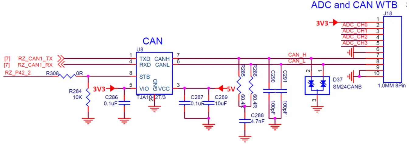
6.10.9 J18: CAN1 and ADC[3:0] interfaces (10-pin WTB header)
- CAN1 TXD and RXD signals are available on the J18 WTB 8-pin connector (This interface has onboard transceiver, termination and ESD protection)
- ADC_CH0..CH3 supports 4x 12bit ADC inputs. (0V~1.8V range, 1us per chan conversion-rate)
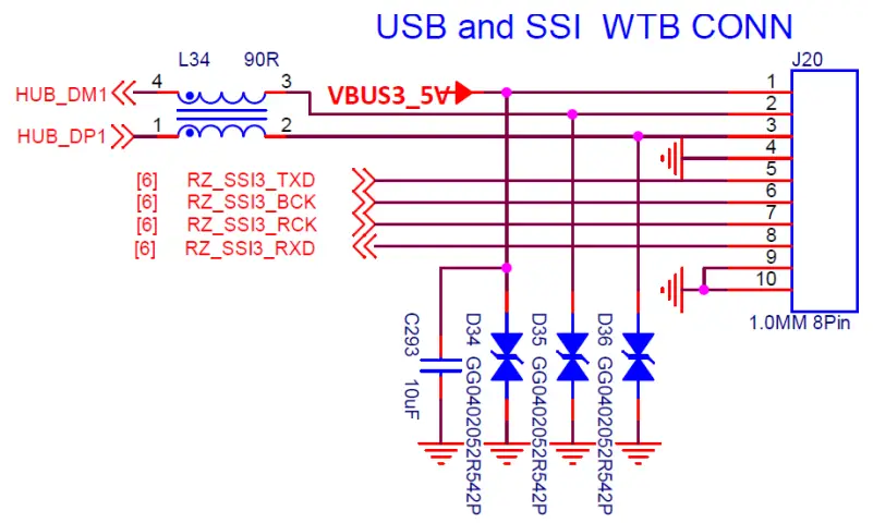
6.10.10 J20: USB1 and SSI3 (10-pin WTB header)
- An ESD-protected USB host interface from RZ_USB1 4-port hub is available on J20
- The 4-wire SSI3 (I2S) digital audio interface on J20 pins
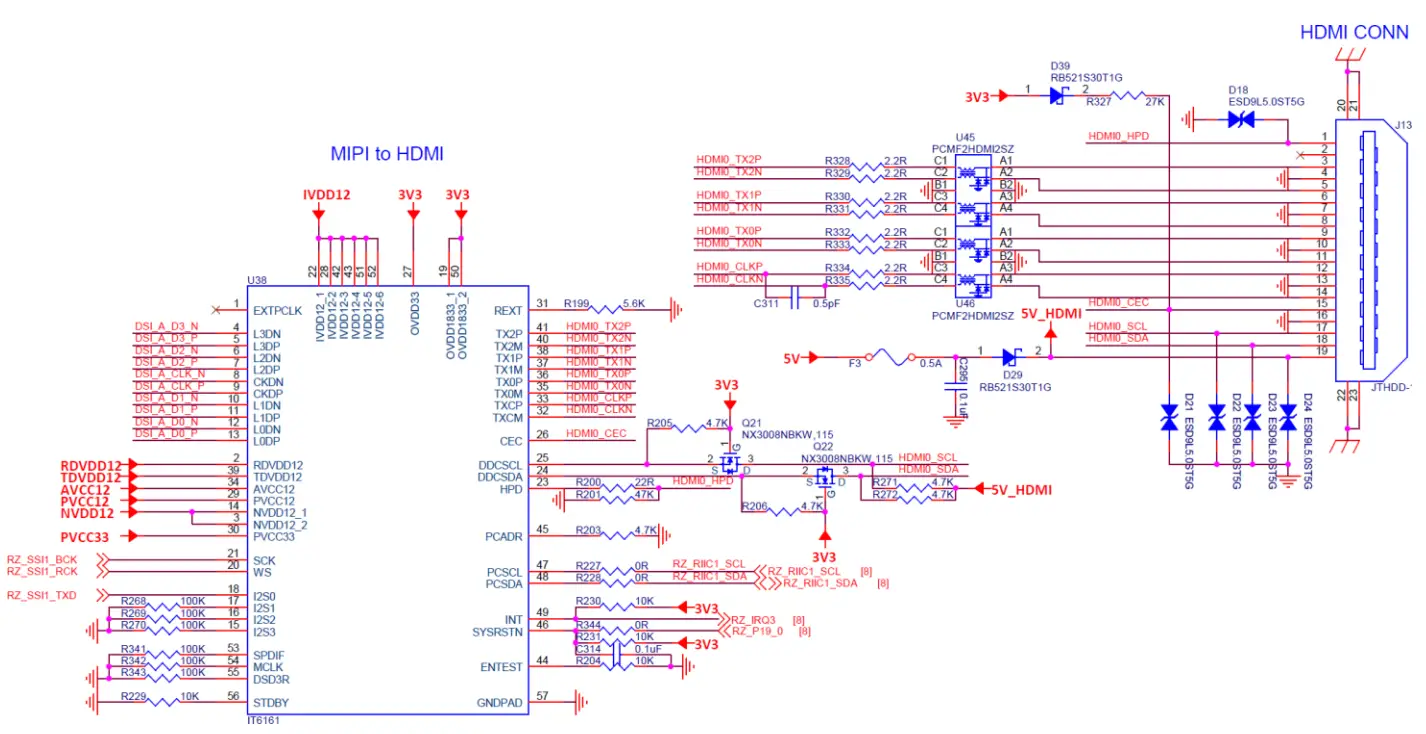
6.10.11 J13: HDMI Display Output
- The 4-lane MIPI-DSI output from the RZ/V2L processor is routed via NX3DV642 high-speed MIPI switch devices to drive either:
a) the J5 MIPI Interface, or
b) the J13 HDMI interface (via the U38 MIPI to HDMI convertor) - MIPI to HDMI conversion is implemented using an IT6161 device
6.10.12 J5: MIPI-DSI Display and Touchscreen Interface
- A 4-lane MIPI-DSI interface is supported plus touchscreen interface.
- This supports the 7-inch MaaXBoard 720 x 1280 display via the 30-pin J5 ribbon connector.
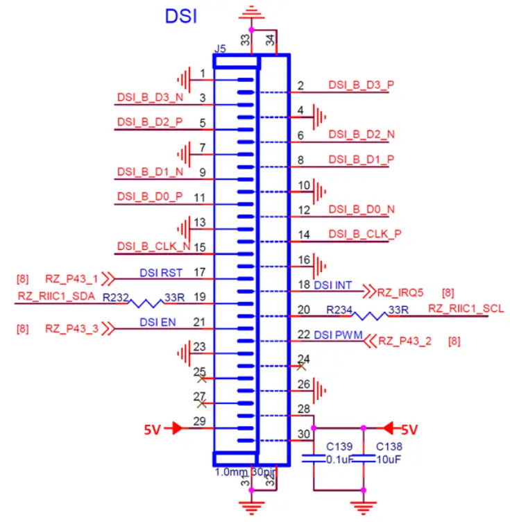
- This 30-pin connector has same form-factor as display connector on Raspberry Pi but the pinout is adapted to include an I2C touchscreen controller interface
| DSI Connector Signal Name | RZ/V2L Processor I/O | MIPI DSI Panel Function |
| DSI_RST | RZ_P43_1 | Display Controller and Touch Controller Reset |
| DSI_EN | RZ_P43_3 | Display Enable |
| DSI_PWM | RZ_P43_2 | Display Backlight PWM |
| DSI_INT | RZ_IRQ5 | Touch Controller Interrupt |
| RZ_RIIC1_SCL | RZ_RIIC1_SCL | Touch Controller I2C Clock |
| RZ_RIIC1_SDA | RZ_RIIC1_SDA | Touch Controller I2C Data |
6.10.13 J4: MIPI-CSI Camera Interface
The 2-lane, 15-pin MIPI connector pinout is the same as what is used on Raspberry-Pi board
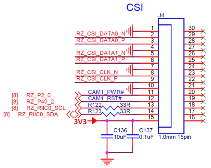
| Camera Control I/O | RZ/V2L Processor I/O |
| CAM1_PWR# | RZ_P2_0 |
| CAM1_RST# | RZ_P40_2 |
| RZ_RIIC0_SCL | RZ_RIIC0_SCL |
| RZ_RIIC0_SDA | RZ_RIIC0_SDA |
6.10.14 J7: Gigabit Ethernet RJ45 Interface
The 10/100 Ethernet subsystem is comprised of:
- AR8035-AL1B Ethernet transceiver (U24) with GRMII interface,
- RJ45 (J7) connector with integrated magnetics.
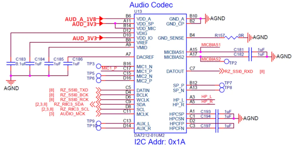
6.10.15 Audio Codec
RZ_SSI0 interface of RZ/V2L (Serial Audio Interface #0) connects to Dialog DA7212-01UM2 stereo audio Codec. PCM audio between Wi-Fi/BT module and the Codec, requires routing through the RZ/V2L processor.
RZ_SCI0 (Serial Communications Interface #1) connects the RZ/V2L processor with the Bluetooth PCM audio interface of the WiFi/BT module.
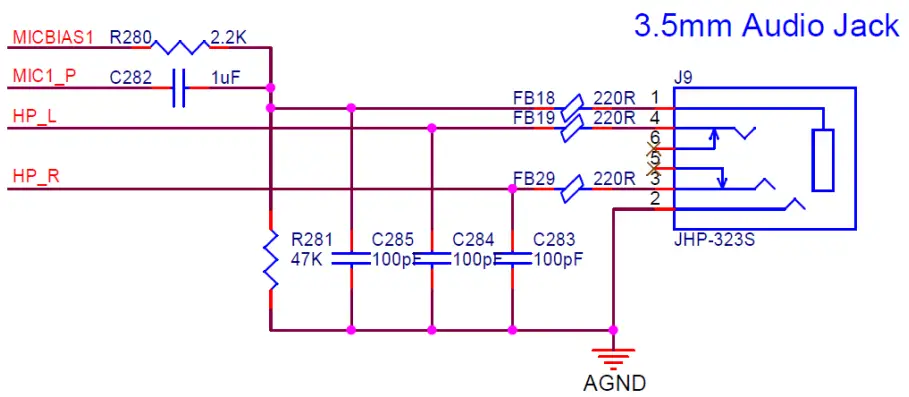
6.10.16 J9: Stereo Audio Jack
6.11 Wireless Connectivity
RZBoard V2L uses a Murata Type-1ZM Wi-Fi 5 and Bluetooth 5 combo module, which is based on the NXP 88W8987 device. Dual-band 2.4 GHz and 5 GHz Wi-Fi operation is supported Interfaces between the 88W8987 based module and the RZ/V2L host processor include:
- Wi-Fi SDIO 3.0 (4-bit) interface (uses RZ_SD1)
- BT/BLE UART 4-wire interface (uses RZ_SCIF1)
- Bluetooth Audio PCM interface (uses RZ_SCI0)
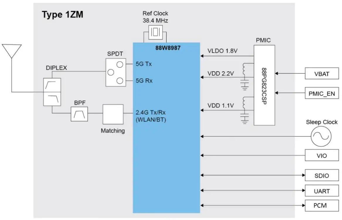
Figure 6 – Murata Type-1ZM Wi-Fi/BT Combo Module Block Diagram
6.11.1 Wi-Fi SDIO Interface
RZ_SD1 interface is configured for 1.8V operation and is clocked at 200 MHz (This is the same SDIO interface as used on the RZ/V2L-EVK)
| RZ/V2L Signal Name | 1ZM Module WLAN Pin Name |
| RZ_SD1_[D3:D0] | SD_DAT[3:0] |
| RZ_SD1_CMD | SD_CMD |
| RZ_SD1_CLK | SD_CLK |
| RZ_P7_1 | WL_WAKE_HOST |
| RZ_P8_0 | HOST_WAKE_WLAN |
| RZ_P39_2 | PMIC_EN |
Table 8 – Wi-Fi Interface
6.11.2 BT/BLE UART Interface
RZ_SCIF1 including hardware flow is routed from the RZ/V2L via a 3.3V to 1.8V level-shifter, to the 1ZM module’s Bluetooth UART interface. (Note uses of LPUART10 interface is different from what used on the RZ/V2L-EVK, which uses LPUART2 for this interface)
| RZ/V2L SCIF Signal Name | 1ZM Module BT Pin Name |
| RZ_SCIF1_RXD | BT_UART_TXD |
| RZ_SCIF1_TXD | BT_UART_RXD |
| RZ_SCIF1_RTS | BT_UART_CTS |
| RZ_SCIF1_CTS | BT_UART_RTS |
| RZ_P7_2 | HOST_WAKE_BT |
| RZ_P7_0 | BT_WAKE_HOST |
Table 9 – Bluetooth Data Interface
6.11.3 BT PCM Audio Interface
RZ_SCI0 is routed from the RZ/V2L via a 3.3V to 1.8V level-shifter, to the Murata 1ZM module’s Bluetooth UART PCM audio interface.
| RZ/V2L SCI0 Signal Name | 1ZM Module BT Audio Pin Name |
| RZ_SCI0_TXD | BT_PCM_DIN |
| RZ_SCI0_CTS | BT_PCM_SYNC |
| RZ_SCI0_SCK | BT_PCM_CLK |
| RZ_SCI0_RXD | BT_PCM_DOUT |
Table 10 – Bluetooth Audio Interface
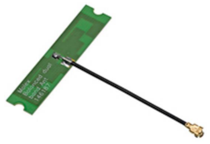
6.11.4 Wi-Fi / BT antenna
This board only supports an external antenna, attached via UFL / IPEX MHF connector.
The antenna shipped with RZBoard V2L (as used in regulatory certifications) is Molex p/n: 1461870050
6.12 Power Architecture
RZBoard is a power-efficient low-wattage board (typical 1.5W ~ 4.5W depending on use case)
6.12.1 Power Input (+5V USB type-C Connector)
The USB type-C connector is used for 5V power input (It does not support a data interface)
6.12.2 Power Regulation (RAA215300 PMIC: 6 Buck Regulators, 3 LDOs)
The Renesas PMIC efficiently converts the 5V power input into multiple regulated supply rails Power architecture of RZBoard is based on the Renesas diagram below
(See table for detail on RZBoard’s specific usage of the PMIC output rails)
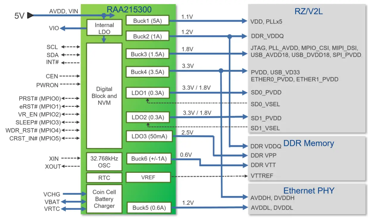
| PMIC Voltage Regulator | RZBoard Power Rail | Power Rail Connects To… |
| BUCK1 | VDD_1V1 | VDD, PLLx5 |
| BUCK2 | VDDQ_DDR_1V2 | DDR_VDDQ |
| BUCK3 | 1V8 | JTAG, PLL_AVDD, MPIO_CSI, MIPI_DSI, USB_AVDD18, USB_DVDD18, SPI_PVDD, ADC, eMMC, QSPI, Codec, WiFi/BT, Level-shifters |
| BUCK4 | 3V3 | PVDD_1, PVDD_2, USB_VD33, Clock module, ETHER0_PVDD, ETHER1_PVDD, USB hub, CSI camera, IT6161, MIPI switches, CAN, Pi-HAT header, SD card, SD/eMMC switch, eMMC, Codec, Level-shifters |
| BUCK5 | 1V2 | IT6161 (6x power rails) |
| BUCK6 | VTT_DDR | (Unused) |
| LDO1 | SD0_PVDD | SD0_PVDD |
| LDO2 | TP23 | (Unused) |
| LDO3 | VPP_DDR_2V5 | SD1_PVDD |
| VREFOUT | VREF_DDR_0V6 | VREFCA (DDR4) |
| VIO | VIO_1V8 | (Unused) |
6.12.3 Power Consumption Measurements
An inexpensive current-measurement USB dongle is recommended during development, in-line with the USB power connection to monitor 5V input current draw. The USB dongle meter shown here accommodate type-C and type-A cable connections and is available online for around $20 https://www.amazon.com/Tester-Eversame-Voltmeter-Ammeter-Braided/dp/B07MGQZHGM
Note: An invalid current measurement will be seen if RZBoard V2L is powered from a USB port of same PC as used by the debugger probe! To achieve a useful current measurement, power RZBoard from a separate power-adapter, or disconnect the debugger probe.

6.13 ESD Protection
All USB interfaces and the HDMI interface have high-speed ESD protection discrete devices on their power rails and data lines. The CAN1 interface also includes ESD protection.
Technical Support
7.1 Renesas-hosted Technical Support Resources
Renesas Support Portal
Technical support of RZ/V2L software enablement plus the broader RZ family is available via the Renesas Portal for knowledge base, FAQs and Support Forums, eg.
https://en-support.renesas.com
https://en-support.renesas.com/knowledgeBase/category/31243 (requires Renesas login)
Renesas RZ/V2L and RZ/G2L SMARC Wiki Pages
https://renesas.info/wiki/RZ-V/RZ-V2L_SMARC
https://renesas.info/wiki/RZ-G/RZ-G2L_SMARC
Renesas Github Repos
Renesas maintains various github repositories in context of RZ/V2L, eg.
https://github.com/renesas-rz/rz_linux-cip
https://github.com/mkosinski05/meta-renesas-ai
7.2 Avnet-hosted Technical Support Resources
For general RZBoard V2L questions, visit the product page at http://avnet.me/RZBoard-V2L where you will find technical documentation, videos and tutorials, reference designs and other support.
Detailed questions regarding RZBoard V2L hardware design, software application development, training and use of related tools, can be posted on the RZBoard Support Forum at http://avnet.me/RZBoard-forum
(This forum is monitored by technical resources in Avnet’s Advanced Applications Group)
If interested in customization of RZBoard V2L with customer-specific options, send an email inquiry with detail of desired changes (and use-case) to [email protected]
Sales Contact Info
For further info on Avnet-designed Development Boards, contact your local Avnet representative at:
| Region | Organization | Contact Webpage | Address & Phone |
| North America | Avnet Americas | www.avnet.com/contact | 2211 South 47th Street Phoenix, AZ 85034, USA Phone: +1-800-585-1602 |
| EMEA | Avnet Silica | avnet-silica.com/contact | Gruber Str. 60c 85586 Poing, Germany Phone: +49-8121-77702 |
| EMEA | EBV | ebv.com/contact | Im Technologypark 2-8 85586 Poing, Germany Phone: +49-8121-774 – 0 |
Cautionary Notes
ESD – Handling precautions for ESD-vulnerable electronic equipment are strongly recommended. It is advised to touch the metal housing of Ethernet or USB connectors, prior to touching any other part of the PCB.
Connectors – Use care when inserting/unplugging cables, especially with USB-C and audio jack connectors. Finger-support is advised to brace surface mount connectors against excessive lateral force.
MIPI Connectors – The locking mechanism of MIPI-DSI and MIPI-CSI ribbon cable connectors are relatively fragile and should be handled with care. Make sure of alignment and use minimal force when locking.
OTP eFuses – For security reasons, the on-chip OTP fuses in the RZ/V2L are one-time programmable. During application development, there should never be a need to program these fuses. Two boot modes are supported via selection jumper (J19). Programming of OTP eFuses will only be necessary when deploying this board in an end-product. It is the user’s responsibility to be absolutely certain of their requirements before OTP programming and to not program the fuses by accident.
Note that Avnet accepts no liability and will not replace boards that have been:
- Damaged by ESD or mishandling.
- Compromised through OTP eFuse programming
Safety Warnings
- It is recommended that this product only be powered via the onboard USB type-C connector, from one of the following +5V power sources:
a) Connected to the development computer (depends on use-case)
b) Connected to a 5V power-bank battery of suitable rating
c) Connected to an external +5V, 1A DC power adaptor (a higher rating may be needed if an expansion Pi_HAT or custom board is fitted). The external power supply shall comply with relevant regulations and standards applicable in the country of intended use. - Only compatible plug-in modules shall be connected to RzBoard V2L. Connection of incompatible devices may affect compliance or result in damage to the unit and void the warranty.
- This product must be operated in a well-ventilated environment.
If an enclosure is used, this must provide adequate ventilation. - Do not insert or remove any expansion board or cable, without first unplugging the relevant +5V DC power source
- Ambient operating temperature range when using RzBoard V2L shall not exceed: -30C to +85C
Disclaimer
RZBoard V2L is engineered for use as a development board (to facilitate product evaluation and systemlevel prototyping) as well as for potential use as a sub-assembly in custom OEM end-products.
Avnet assumes no liability for modifications that a user chooses to make to RZBoard V2L.
Software: eMMC Memory and Device Tree Overlays
12.1 Procedure to Reflash the Bootloader Firmware (eMMC)
Typically not necessary to update the bootloader (the Linux System Image is what usually gets updated!)
Bootloader programming is however detailed below.
| .BAT File Name | File Size | File Names | Boot Mode Board Settings |
| flash_bootloader.bat Download Type: SCIF0 @115.2 kb/s | 268 KB 115 KB 2.02 MB | • flashwriter_RZBoard.mot • bl2_bp-RZBoard.srec • fip-RZBoard.srec | BOOT2=1: Fit fly-wire from J1 pin2 to J19 pin1 BOOT1=0: Set SW1.1 = ON BOOT0=1: Remove SD card |
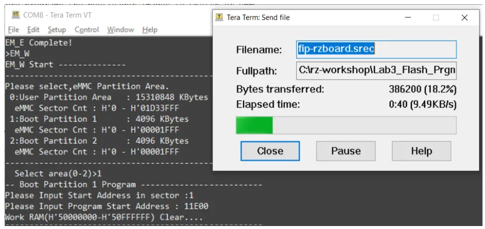
RZBoard supports an easy scripted procedure to program the following bootloader image files via SCIF serial download from the development computer into RZBoard’s eMMC flash memory.
- flashwriter_RZBoard.mot FlashWriter image tool
Once downloaded, this is used to program the following two bootloader images into eMMC - bl2_bp-RZBoard.srec bootloader image in Motorola S-Record format, ARM TFA (Trusted Firmware-A ) BL2 image
- fip-RZBoard.srec which is a combination of bootloader image, ARM TFA (Trusted Firmware-A ) BL31 and u-boot combined image
Note: Complete steps 1-6 below, prior to running the provided flash_bootloader.bat file:
- Download the latest image files, .bat and macro files from https://avnet.me/RZBoard_emmc and extract the zipped files to a staging folder on the development computer
- Edit Windows Ethernet network adapter settings for the development computer: Set it’s IPv4 properties to static IP Address 192.168.1.88
- Edit the config.ini file (update the COM port#, check for matching names of BootLoader image files)
- Power-off RZBoard
- Place RZBoard into “SCIF download boot-mode” by setting BOOT[2:0] to b101 (as tabled above), ie.
a) Set BOOT2=1 by strapping J19-pin1 to +5V (ie. connect it to J1-pin2 on the 40pin header)
b) Set BOOT1=0 by strapping SW1.1 = ON
c) Set BOOT0=1 by removing SD card from MicroSD slot - On RZBoard’s J19 Debug UART 4-pin header, connect the fly-leads from the USB-Serial cable connected to the development computer.
 Run flash_bootloader.bat (this launches a Tera Term macro using the edited config.ini settings)
- Press and hold S1 for 2 seconds to power-on RZBoard, the macro will now proceed. Wait for this to complete (<5 min)

 Run flash_bootloader.bat (this launches a Tera Term macro using the edited config.ini settings)
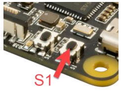
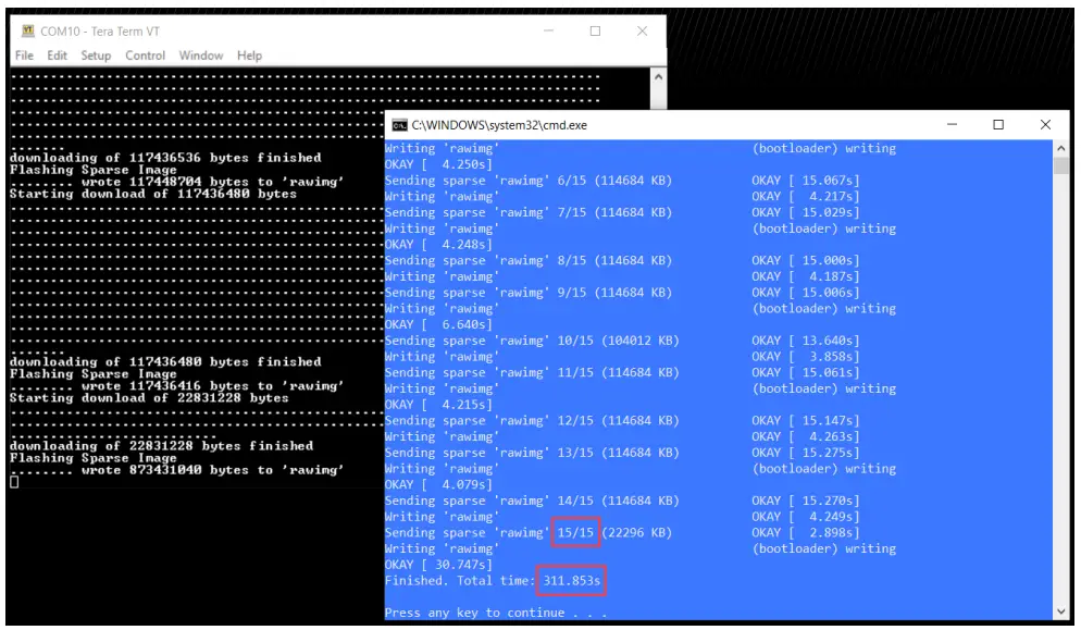
12.2 Procedure to Reflash the Linux System Image (eMMC)
| .BAT File Name | File Size | File Names | Boot Mode Settings |
| flash_system_image.bat Download Type: Ethernet Fastboot @1 Gb/s | 2.53 GB *typical | core-image-RZBoard- 20220920085823.rootfs.wic | BOOT2=0: Remove fly-wire from J1 pin2 to J19 pin1 BOOT1=0: Set SW1.1 = ON BOOT0=1: Remove SD card |
RZBoard supports an automated procedure to program the large Linux System Image file, into RZBoard’s
eMMC flash memory, via Gigabit Ethernet from the development computer.
Note: Complete steps 1-6 below, prior to running the provided flash_system_image.bat file:
- Download the image files, .bat and macro files from https://avnet.me/RZBoard_emmc and extract the zipped files to a staging folder on the development computer
- Edit Windows Ethernet network adapter settings for the development computer: Set it’s IPv4 properties to static IP Address 192.168.1.88
- Edit the config.ini file (update the COM port#, the IP address and name of the System image file)
- Power-off RZBoard
- Place RZBoard into “eMMC (1V8) boot-mode” by setting BOOT[2:0] to b001 (as tabled above), ie.
d) Set BOOT2=0 by removing fly-wire from J19-pin1 to J1-pin2 (40pin header)
e) Set BOOT1=0 by strapping SW1.1 = ON
f) Set BOOT0=1 by removing SD card from MicroSD slot - Run flash_system_image.bat (launches applicable Tera Term macro using saved config.ini settings)
- Power-on RZBoard. Ethernet connection will be established and a blue window shall open in <30 sec. Wait for the macro to complete (typically 15 blocks of data are sent and this completes in <5 min)

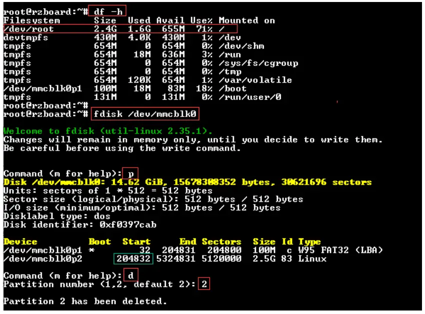
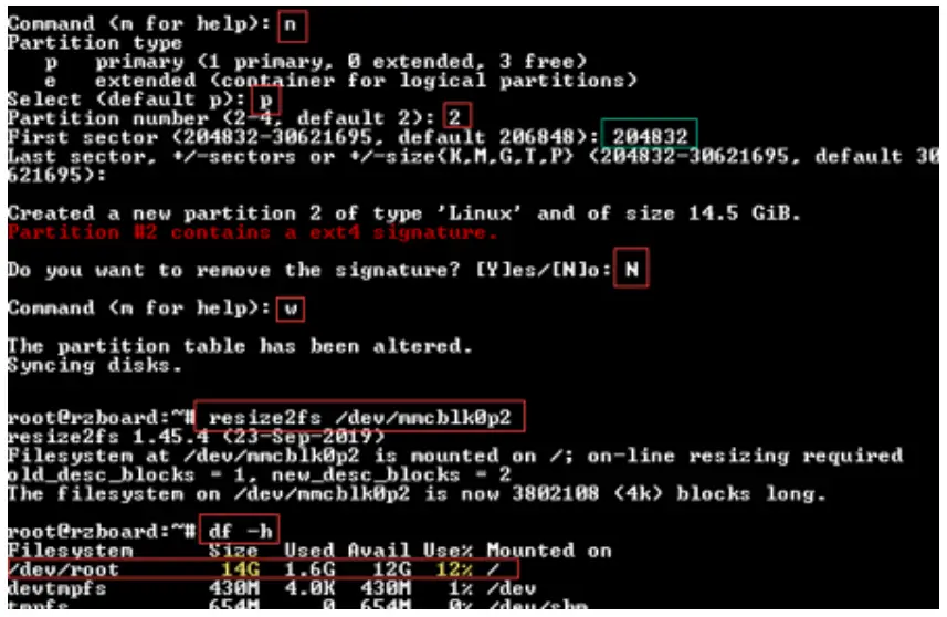
12.3 Procedure to Increase the eMMC Partition Size
Caution: A miss-step in this procedure can delete all files on your board!
As configured during manufacture, only a section of the 32GB eMMC is accessible.
Use the following steps to expand the rootfs partition in eMMC flash memory:
- Open a serial port connection to RZBoard’s debug connector
- Boot Linux and login to the board with user: root and password: avnet
- Execute the command fdisk /dev/mmcblk0
- Make note of the mmcblk0p2 start address displayed on the screen
- Execute the following sequence of commands: p -> d -> 2 -> n -> p -> 2 -> <mmcblk0p2 start address> -> enter (to accept default) -> N -> w
- Now resize the partition using the entered settings: resize2fs /dev/mmcblk0p2


12.4 Linux Device Tree Description of RZBoard Hardware
At startup, u-boot loads the RZBoard.dtb device tree blob, plus whatever device tree overlays have been specified by the user in the uEnv.txt (u-boot environment) file.
To configure Linux to use the MIPI DSI display (rather than default HDMI output) or to support peripherals such as I2C, SPI, CAN, ADC, Audio Codec, etc, requires that specific device tree overlay files be enabled. The available device tree overlay files are located in the file-system /boot/overlays/ folder
| Config to enable | Value if set | File that this loads |
| enable_overlay_disp | ‘hdmi’ ‘mipi’ | RZBoard-hdmi.dtbo RZBoard-mipi.dtbo |
| enable_overlay_camera | ‘ov5640’ sas02601 | RZBoard-ov5640.dtbo RZBoard-as0260.dtbo |
| enable overlay_adc | ‘1’ or ‘yes’ | RZBoard-adc.dtbo |
| enable overlay_can | ‘1’ or ‘yes’ | RZBoard-can.dtbo |
| enable overlay_cm33 | ‘1’ or ‘yes’ | RZBoard-cm33.dtbo |
| enable overlay_audio | ‘1’ or ‘yes’ | RZBoard-lite-audio.dtbo |
| enable overlay_i2c | ‘1’ or ‘yes’ | RZBoard-ext-i2c.dtbo |
| enable overlay_spi | ‘1’ or ‘yes’ | RZBoard-ext-spi.dtbo |
| enable_overlay_uart2 | ‘1’ or ‘yes’ | RZBoard-ext-uart2.dtbo |
| fdtfile : is base dtb file, should be set to RZBoard.dtb | ||
| fdt_extra_overlays : other dtbo files to load eg. RZBoard-f1.dtbo RZBoard-f2.dtbo | ||
| uboot env : Use env set to add u-boot environment variables, eg. ‘console=’ ‘bootargs=’ | ||
Default uEnv.txt setting:
fdtfile=RZBoard.dtb
enable_overlay_disp=hdmi
#fdt_extra_overlays=1.dtbo 2.dtbo 3.dtbo
#ethaddr=aa:bb:cc:aa:bb:cc
Refer to RZBoard V2L Linux Yocto User Manual for further detail of the Linux BSP software support provided for the RZBoard V2L hardware.
Accessories: RZBoard V2L Add-On Options
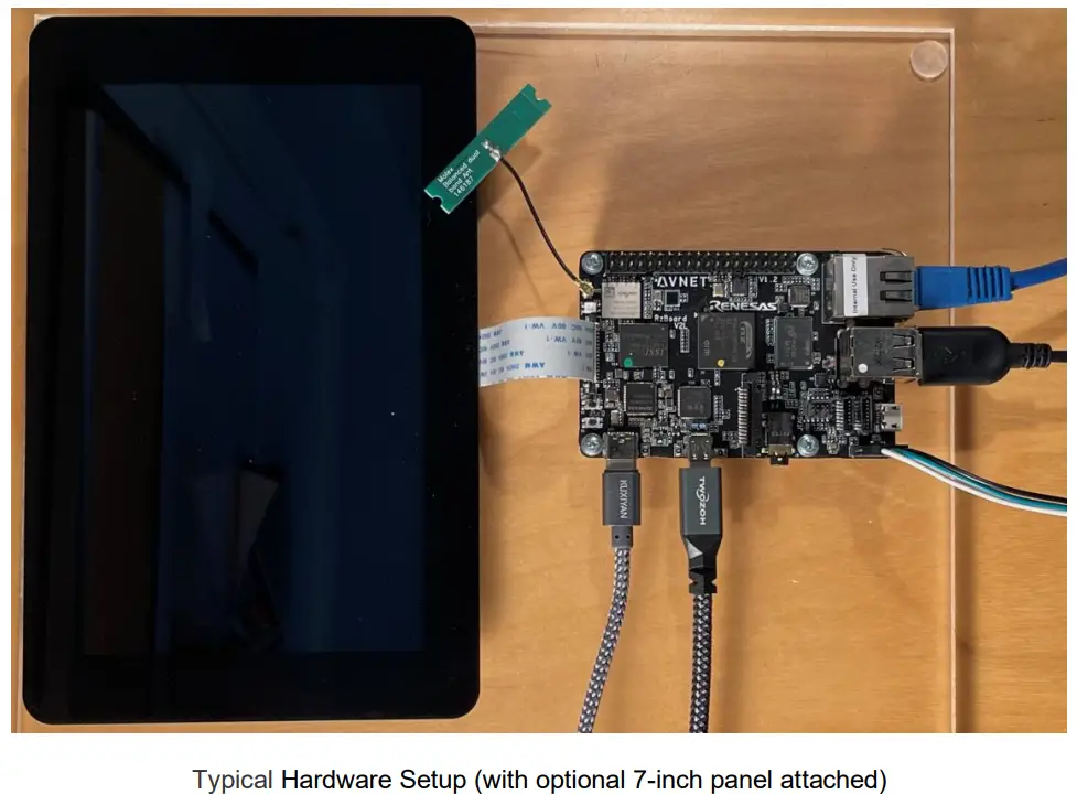
13.1 MIPI DSI 7-inch Capacitive Touch LCD Display (Optional)
- Supports up to 1280 x 720 resolution
- Compatible with all MaaXBoard SBC platforms.
- Connects to host via 2-lane MIPI-DSI interface
- Capacitive multi-touch display overlay
- Custom displays available via Avnet Embedded
Part# (and link): AES-ACC-MAAX-DISP2 (MSRP = $95.00)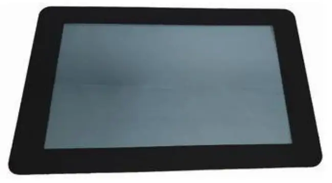 13.2 MIPI CSI 5 MP Camera (Optional)
- High quality 5 MP image sensor
- Compatible with all MaaXBoard SBCs and Raspberry Pi
- Attaches to host via 2-lane MIPI CSI ribbon cable
- Supports 1080p30, 720p60 and 640x480p90 video
- Small dimensions (24mm x 25mm x 9mm)
Part# (and link): AES-ACC-MAAX-CAM1 (MSRP = $31.95)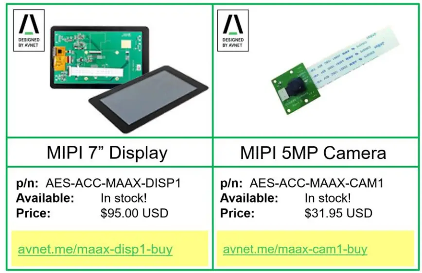
13.3 Other SBCs, SOMs and Accessories from “Avnet Boards”
The engineering team in Avnet’s Advanced Application Group, work in close partnership with key suppliers to develop a range of enablement solutions:
- Kits / Boards / SOMs / Modules
- Reference Designs
- Trainings / Tutorials / Blogs


For more information, visit avnet.me/avnetboards
Solutions Guides are also available for download: 
avnet.me/mpu-mcu-solutions-guide-2022
avnet.me/xlx-solutions-guide-2022 ![]()
References
 Locations and Contacts | Avnet Silica
 Avnet Boards
-
Click Boards - MIKROE
-
RZBoard - Avnet Boards Forums - element14 Community
-
RZBoard V2L | Avnet Boards
-
avnet.me/xlx-solutions-guide-2022
 Contact Us | EBV Elektronik - Avnet
-
Avnet Locations | Avnet Offices & Address
-
Sign in to your account
-
RZBoard V2L | Avnet Boards
-
en-support.renesas.com
-
en-support.renesas.com/
-
en-support.renesas.com/knowledgeBase/category/31243
 GitHub - mkosinski05/meta-renesas-ai: Renesas RZ/G AI BSP
-
GitHub - renesas-rz/rz_linux-cip
-
Raspberry Pi GPIO Pinout
-
RZ/G2L, RZ/G2LC, RZ/G2UL SMARC Board by Renesas - Renesas.info
-
RZ/V2L SMARC Board by Renesas - Renesas.info
-
USB C Power Meter Tester, Eversame USB Voltmeter Ammeter Load Tester,USB Voltage and Current Monitor with Braided USB C to USB C Cable(1.5Ft/50cm)-Test USB Cable Speed - PD 2.0/3.0 QC 2.0/3.0/4.0: Amazon.com: Industrial & Scientific
-
AES-ACC-MAAX-DISP2 by Avnet Engineering Services LCD Displays | Avnet
-
MaaXBoard RT | Avnet Boards
-
Click Boards - MIKROE
-
Molex Connector Part Number - 146187-0050 | Molex
-
renesas.com/document/mah/rzv2l-group-users-manual-hardware?language=en&r=1496691
-
e² studio | Renesas


