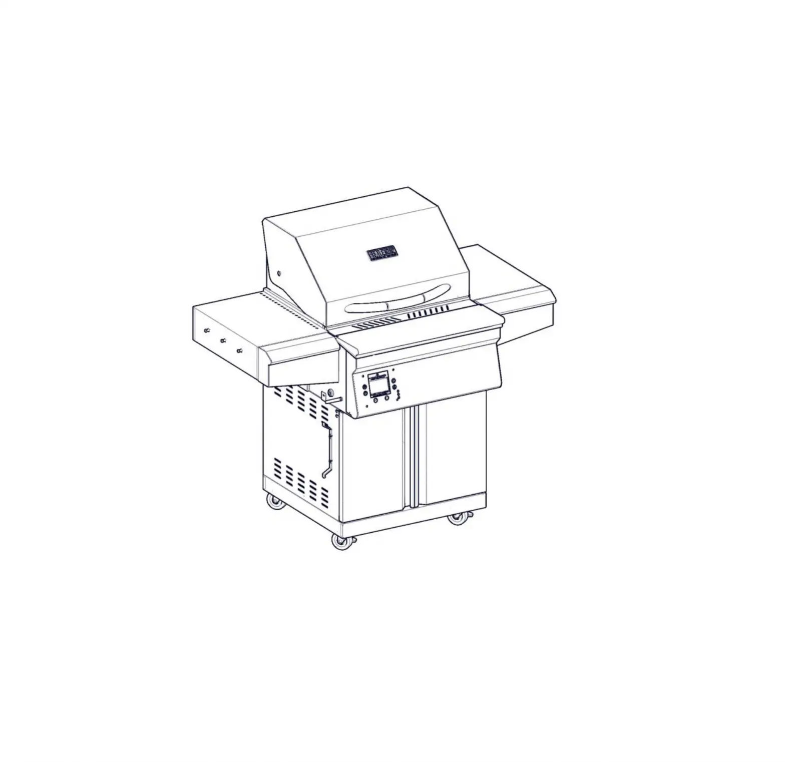
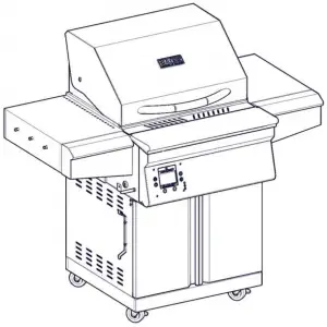
MEMPHIS BGSS26 Beale Street
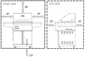
CLEARANCE TO COMBUSTIBLE MATERIALS
YOUR BEALE STREET GRILL MUST MAINTAIN THE SPECIFIED CLEARANCE TO COMBUSTIBLE MATERIALS WHILE OPERATING THE GRILL OR WHILE THE GRILL IS HOT!
Below are some guidelines to ensure safe operation of your Beale Street Grill
|
A MAJOR CAUSE OF FIRES IS FAILURE TO MAINTAIN REQUIRED CLEARANCES (AIR SPACES) TO COMBUSTIBLE MATERIALS. IT IS OF THE UTMOST IMPORTANCE THAT THIS PRODUCT BE INSTALLED ONLY IN ACCORDANCE WITH THESE INSTRUCTIONS |
Required Tools : Phillips Screw Driver and Cut Resistant Gloves
USE CAUTION DURING ASSEMBLY. METAL EDGES MAY BE SHARP.
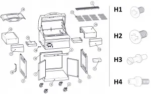
Bill of Materials
BOM # | Part Name | Qty. |
1 | Upper Grate | 1 |
| 2 | Cabinet Front Bracket | 1 |
3 | Caster and Hardware Kit | 1 |
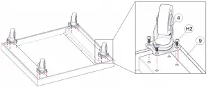
| 4 | Casters | 4 |
5 | Cabinet Left Side | 1 |
| 6 | Cabinet Right Side | 1 |
7 | Cabinet Door Left | 1 |
| 8 | Cabinet Door Right | 1 |
9 | Cabinet Bottom | 1 |
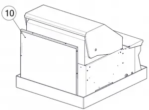
| 10 | Cabinet Back | 1 |
11 | Shelf Front Left | 1 |
| 12 | Shelf Body Left | 1 |
13 | Shelf Front Right | 1 |
| 14 | Shelf Body Right | 1 |
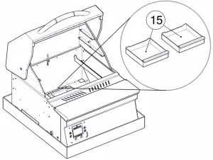
15 | Grease Tray | 2 |
| 16 | Flavorizer | 1 |
17 | Main Grates | 4 |
| 18 | Power Cord Wrap | 1 |
19 | WiFi Antenna | 1 |
Hardware Kit
BOM # | Part Name | Qty. |
H1 | M5 x 12 Phillips Screw | 14 |
| H2 | M6 x 15 Phillips Screw | 46 |
H3 | Tool Holder | 6 |
| H4 | Door Bottom Pivot | 2 |
Unboxing
Remove packaging materials and set aside BOM items for use later.
! Remove plastic protective film from all parts before continuing. !
After grill is used, this film will melt and is impossible to remove cleanly.
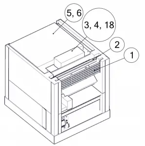
Cabinet Assembly
Open caster and hardware box (#3). Set aside power cord wrap (#18) for later use.
Attach 4x casters (#4) to cabinet bottom (#9) using 4x M6 Phillips Screws (H2) per caster.
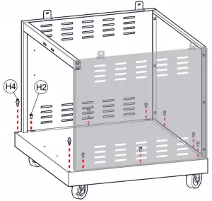
Assemble cabinet sides and back using 6x M6 Phillips Screws (H2).
Attach cabinet front bracket to sides using 4x M5 Phillips Screws (H1).
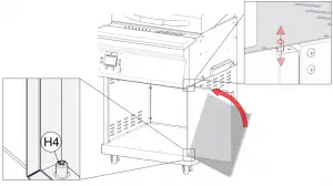
Screw Door Bottom Pivots (H4) into cabinet bottom (#9), unthreaded side up.
Secure the cabinet walls to the cabinet base using 8x M6 Phillips Screws (H2).
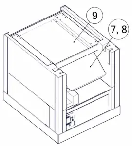
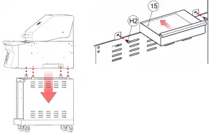
Align mounting holes of grilling chamber with cabinet slots.
Attach cabinet and grill head using 2x M6 Phillips Screws (H2) per side.
Tilt, then slide 2x Grease Trays (#15) into place.
Repeat for opposite side.
Tilt door into Door Bottom Pivot (H4), then push down spring loaded upper pivot on door while rotating door underneath the grill head
Align upper pivot with hole in grill body as shown.
Repeat for other door.
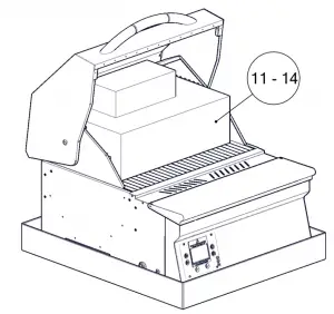
Shelf Assembly
Tighten 3x Tool Holders (H3) per shelf into place as shown.
Use 4x M5 Phillips Screws (H1) per shelf to attach shelf front to shelf body.
Repeat for other side shelf.
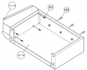
! Tighten screws carefully to avoid stripping out thread or Phillips drive !
Thread 2x M6 Phillips Screws (H2) into the outer top shelf mounting holes as shown. Leave loose so that shelf keyholes can fit over.
Slide shelf onto the two outer top screws using keyholes on shelf.
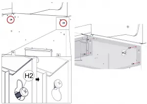
Secure shelf using 4x M6 Phillips Screws (H2) through the shelf body into the grill body. A screwdriver works best in this tight space.
Repeat for opposite side.
Final Assembly
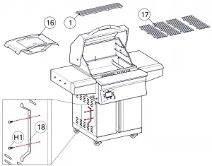
Place Flavorizer (#16) back into original packaged position.
Place 4x Main Grates (#17) back into grill.
Place upper grates (#1) onto either of the upper grate holders
Secure the tool holder to the left side panel using 2x M5 Phillips screws (H1)
MEMPHIS WI-FI SET UP GUIDE
ON YOUR GRILL CONTROLLER:
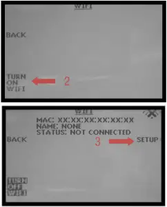
- A Wi-Fi connection can be set up in minutes on your Memphis Wood Fire Grill. First power the grill ON by pressing the top left button
 on the controller, then from the home screen press the “MENU” button, then the “DOWN ARROW”, then the “WIFI” button.
 - The “WIFI” screen on your grill contains everything needed to connect your grill to a Wi-Fi network. First, you will notice that Wi-Fi is OFF, this is enabled as default for users not wishing to use Wi-Fi. To turn Wi-Fi ON, simply press the button “TURN ON WIFI”.
- Next, press and release the “SETUP” button and the grill will start searching for all nearby Wi-Fi networks.
Once the status field displays “CONNECTING” the grill is ready to be connected to your network via any Wi-Fi compatible device.
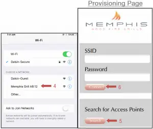
ON YOUR PHONE OR TABLET: (UNDER WIFI SETTINGS) - Simply go to available Wi-Fi networks on your phone or tablet and select the network “Memphis Grill XX:XX”
NOTE: The XX:XX characters will match the last 4 digits shown on the grill controller next to MAC. - Once selected, the grills network will automatically bring you to a page where you will connect your grill to your Wi-Fi network. Search for all networks in range by hitting “Search”, all networks in range are displayed. Click on the network desired and it will auto populate the “SSID” field with your selection. Enter your networks password if you have one. If the network does not require a password, leave the password field blank.
NOTE: Some devices will not bring up the page shown automatically. Once your device is connected to the grill’s network, you can visit www.wificonfig.com to manually bring up the provisioning page - Click “CONNECT” and the page will automatically close.
- The Wi-Fi setup is now complete. The status field in the grills Wi-Fi menu should now read “WIFI CONNECTED”. The time period from hitting “CONNECT” to “WIFI CONNECTED” can take up to 3 minutes based on connection strength.

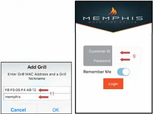
ON YOUR PHONE OR TABLET: (IN THE MEMPHIS GRILLS APP) - Download our app “MEMPHIS GRILLS” from the IOS App Store or Google Play Store.
- Enter a valid email into the “CUSTOMER ID” field and create a password that you will use to login to the app. After logging in, you will receive an email requiring you to confirm your email address before continuing.
- Once the confirmation link is followed from your email, return to the app.
- Once confirmed, login to the app again and you will be able to add your grill. Enter the exact MAC Address and Name shown on the grill controller
Example: MAC: F8:F0:05:F4:A8:12 NAME: MEMPHIS
NOTE: THERE ARE ONLY NUMERICAL O’S IN THE MAC ADDRESS, NO ALPHABETICAL O’S. NICKNAME IS NOT CASE SENSATIVE. INCLUDE COLONS IN THE MAC ADDRESS AS SHOWN.
SETUP IS NOW COMPLETE!
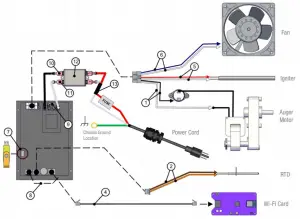
Wiring Diagram
NOTE: ALL TWO WIRE PAIRS FOR A SPECIRC COMPONENT ARE REVERSABLE
Example: Toe auger motor wiring can have the either spade connector from its two wire pair attached to ether terminal and the motor will function normally.
Item # | NAME | Wire Identification | DESCRIPTION / INSTRUCTION |
| 1 | Auger Motor Wiring | 1x Black Wire, 1x White Wire Snap Disk Leads Extending from Auger Motor | Attach the white wire shown to one of the leads extending from the auger motor. Attach the black wire to the snap disk as shown. The 2nd lead extending from the auger motor attaches to the opposite side of the snap disk as shown. The snap disk is a thermal switch which will cut power to the auger motor in the event that its critical temperature is reached. |
| 2 | RTD Wiring | 1x Orange Wire, 1x Brown Wire | Attach both spade connectors to the leads extending from the RTD as shown above. |
| 3 | Grounding Wire | Green Wire | The connection point for the ground is located on the auger motor gearbox body as shown. |
| 4 | Ethernet Cable | Black Cable with Ethernet End | Attach the Ethernet cable to the terminal on the Wi-Fi card as shown. Ensure that the wiring does not interfere with the auger motor’s moving components. |
| 5 | Igniter Wiring | 1x Red Wire, 1x White Wire | Attach both spade connectors to the leads extending from the igniter. These leads will extend from next to the fan. |
| 6 | Fan Wiring | 1x Blue Wire w/ 2 spade ends, 1x White Wire w/ 2 spade ends | Attach the connections on this jumper to the two tabs located on the side of the fan housing. |
| 7 | USB Port | N/A | Used to update your grill, see the “Updating Controller Software” section of the main manual for information. |
| 8 | Meat Probe Wiring | 1x Red Wire 1x Black Wire, Wires twisted around each other | This terminal is used to connect the meat probes to the controller |
| 9 | 120/240 Select Jumper | 1x Black Wire | Used when changing the input voltage to the controller, see “120v to 240v Conversion” section of the main manual for information. |
| 10 | AC Load Wire from Filter to Controller | 1x Black Wire | Carries AC voltage from the filter to the control board, load wire. |
| 11 | AC Neutral Wire from Filter to Controller | 1x White Wire | Carries AC voltage from the filter to the control board, neutral wire. |
| 12 | Filter | N/A | Reduces electrical feedback. Line = Outlet Side, Load = Grill Side. L1 = Load L2= Neutral |
| 13 | MOV + Fuse Holder | 1x Red Wire 1x White Wire, Pair is joined in the middle with black shrink wrap. Fuse holder is cylindrical and white plastic. | A two wire component which has a ferrite choke to eliminate input electrical disturbances from the grid. Load and Neutral wires. Fuse holder that accepts |
CONTACT YOUR DEALER OR MEMPHIS GRILLS TECHNICAL SERVICE WITH ANY QUESTIONS.
TECHNICAL SERVICE NUMBER: 1-888-883-2260