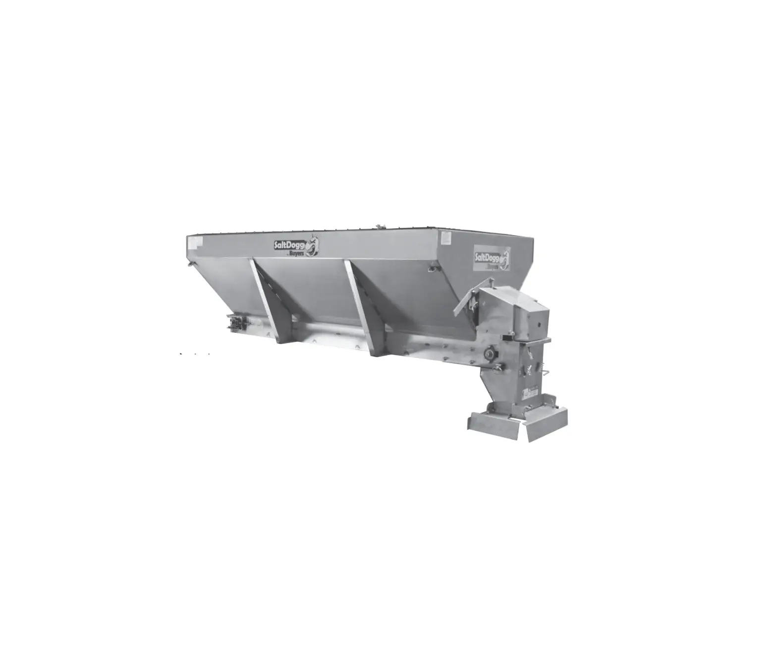
SaltDogg Self-Contained Stainless Steel Hopper Spreaders

SPREADER WARRANTY INFORMATION
This warranty replaces all previous warranties and no employee of this company is authorized to extend additional warranties, or agreements, or implications not explicitly covered herein.
Buyers Products Company warrants all parts of the product to be free from defects in material and workmanship for a period of one (1) year, from the date of installation. Parts must be properly installed and used under normal conditions. Normal wear is excluded.
Any part which has been altered, including modifications, misuse, accident, or lack of maintenance will not be considered under this warranty.
The sole responsibility of Buyers Products Company under this warranty is limited to repairing or replacing any part(s) which are returned, prepaid, 30 days after such defect is discovered, and returned part(s) are found to be defective by Buyers Products Company.
Authorization from Buyers Products Company must be obtained before returning any part. The following information must accompany defective parts returned to Buyers Products Company: RMA#, spreader model, serial number, date installed, and distributor from whom purchased.
Buyers Products Company shall not be liable for damage arising out of failure of any unit to operate properly, or failure, or delay in work, or for any consequential damages. No charges for transportation or labor performed on any part will be allowed under this warranty.
General Information
- Recommended Vehicle Requirements:
• 3/4 or 1 ton Pick-up Truck Above 8500# GVWR - Average Material Weights:
MATERIAL WEIGHT (POUNDS PER CUBIC YARD) #1 Rock Salt 950 #2 Rock Salt 1,215 Coarse Sand – Dry 2,565 Coarse Sand – Wet 3,240 Note: To calculate the total spreader weight (including ice control material); add the empty spreader weight plus the ice control material and spreader accessories.
 CAUTION
Do not overload vehicle beyond the vehicle’s Gross Vehicle Weight Rating (GVWR) or Gross Axle Weight Ratings (GAWR). Check the vehicle’s load rating certification sticker for maximum vehicle capacity. - Hopper Storage Capacity

HOPPER CAPACITIES
96” 72” 12″ .50 CU-YD .36 CU-YD 19″ 1.0 CU-YD .77 CU-YD 27″ 1.80 CU-YD 1.36 CU-YD - Recommended Fastener Torques:
Maintain all fastener torques as shown in the following table. Failure to do so may cause injury to persons.SAE GRADE 2 FT-LBS
SAE GRADE 5 FT-LBS
1/4-20 6
9
5/16-18 11
18
3/8-18 19
31
3/8-24 24
46
7/16-14 30
50
1/2-13 45
75
9/16-12 66
110
5/8-11 93
150
 CAUTION
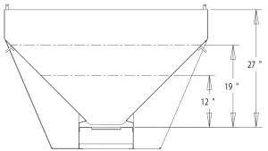
Safety Precautions
|
| Observe the following Safety Precautions before, during and after operating this spreader. By following these precautions and common sense, possible injury to persons and potential damage to this machine may be avoided. |
- Read this entire Owner’s Manual before operating this spreader.
- Read all safety decals on the spreader before operating the spreader.
- Check to make sure all safety guards are securely mounted into place before operating this spreader..
- Make sure the motor cover is securely fastened to the spreader before operating the spreader.
- Verify that all personnel are clear of the spreader spray area before starting or operating this spreader.
- Keep all loose clothing, hair, jewelry and limbs clear of the spreader before starting or operating this spreader.
- Do not over-load your vehicle beyond payload limits. If there are any questions, contact the vehicle manufacturer.
- Do not adjust, clean, oil or unclog material jams without first turning off the spreader.
- Do not climb on or in the spreader during operation. Do not ride on the spreader while the vehicle is in motion.
- Make sure the spreader is securely fastened to the vehicle in accordance with this manual.
- Do not operate a spreader that is in need of maintenance or repairs.
- Always disconnect the wire harness before removing or replacing any electrical components.
Installation Instructions
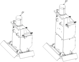
- Mounting the Spreader onto the Vehicle:
A. Remove the tailgate from the vehicle.
B. Lift the spreader by lifting loops on side of hopper.WARNINGThe lifting device must be adequately rated to lift a payload equal to or greater than the spreader weight. See page 1 for spreader weights. Empty spreader before lifting. C. Elevate the spreader off the vehicle with lumber. Place lumber under the side gussets of the spreader. This will help with removal of excess material that accumulates under the spreader.
D. Center the spreader on the vehicle with the end of the gear mount 14″ to the rear of the nearest vertical obstruction (bumper, trailer hitch, etc). Attach chute to spreader, check for interference between the vehicle and the Spinner/Chute Assembly
E. Bolt the spreader to the vehicle frame through the lengths of lumber using the holes located in each of the four (4) side gussets. Use 1/2″ SAE Grade 5 hardware as required by vehicle application.
F. In addition secure the spreader to the vehicle by attaching the four (4) tie-down eyes located at each corner of the spreader to the vehicle’s factory installed anchor points using suitable tiedown devices.
• The spreader must be securely fastened to the frame of the vehicle.
• Verify with the vehicle’s manufacturer that the factory installed anchor points are designed for tie-down of such load.
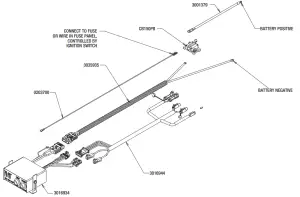
• Periodically check that the spreader mounting hardware is securely tightened, retighten if necessary. - Control Box and Vehicle Wiring Harness Installation
MAKE SURE YOU HAVE CONNECTED THE PROPER WIRE
COLOR.
THIS IS A WIRE GROUND ELECTRICAL SYSTEM!
NO CONNECTIONS TO TRUCK’S FRAME OR BODY ALLOWED!WARNINGWARNING! Do not drill holes into fuel tanks, fuel lines, through electrical wiring, etc. that may be damaged by drilling. To insure good performance of your spreader, check the condition of truck’s electrical system. Using digital voltmeter, check alternator and battery voltage. With engine running and head lights and heater fan ON good voltage reading should fall between 13.0 and 15.3 volts. If voltage reading falls out of this range, check and adjust your electric system. NOTE: Always disconnect battery before attempting to install electrical components on your vehicle.
A. Mount the controller in a convenient location in the truck cab. It is recommended not to mount the controller directly in front of heat vents. Allow ample air space around controller.CAUTIONDO NOT MOUNT CONTROLLER IN THE WAY OF AIR BAG DEPLOYMENT! 
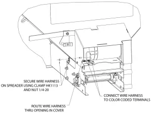
B. Route both wire harnesses into truck cab through firewall (it maybe necessary to drill holes). Insulate hole to avoid water leaks.
C. Insure no wires are nicked or damaged during installation.
D. Connect the 4-pin connector on the wire harness to the control box 4-pin connector.
E. Connect the 2-pin connector on the power cable to the control box mating connector.
F. Connect wire harness single connectors to control box connectors.
G. Connect fuse connector to the fuse terminal or ignition switch (5 AMP max).
H. Lay out a path for the power cable to the battery, use quick ties to secure power cable.
DO NOT CONNECT TO BATTERY AT THIS TIME!
I. Lay out path for wire harness to the rear of the vehicle. It is recommended to stay clear of the exhaust system. Excess heat can damage the wire harnesses. Use quick ties to secure harness to underbody.
J. Connect the wire harness to the motor. Make sure wire colors on wire harness match colors on the motor. Thoroughly clean battery terminals. Make sure battery terminals have no tarnish or corrosion. DO NOT CONNECT WIRE HARNESS TO DAMAGED OR CORRODED TERMINALS! IT MAY RESULT IN OVERHEATING, LOST POWER AND POTENTIAL CONTROLLER DAMAGE!
K. Connect the power cable directly to the battery.
L. Insure all functions of the controller are working properly.
M. Observe chain moving in proper direction. If direction is wrong reverse wires between Motor and Wire Harness.
N. Optional spot light (5 AMP max) can be installed on spreader.
Remove cap from single white wire. Connect light to this wire and trucks frame.IMPORTANTIMPORTANT Make sure all wires securely attached to vehicle or spreader. Use wire ties and/or wire clamps to attach wires. All excess wires must be rolled into bungles and attached to vehicle or spreader. 
- Spinner/Chute Assembly Operation

Attach chute to hopper assembly by inserting tabs into slots in chute motor plate. Then secure chute by engaging spring latches in respective holes. Chute heights can be adjusted by attaching lower chute weldment to the upper one using upper or lower set of holes. Two sets of holes are located on the bottom of upper chute weldment and under internal baffles selectors. Adjustable shaft can be connected in two positions: upper and lower. Two sets of holes are located in upper and lower portions of coupler. Shaft to be secured by 5/16 cross bolt and nut.
A. The spread pattern and the amount of material dispensed is dependant on the following factors:
1. Gear Motor RPM
2. Feed gate position
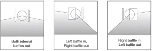
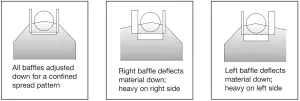
3. Baffle settings
4. Spinner Motor RPMBelow are illustrations that show the baffles effect on the spread
pattern as viewed from the top of the spinner disk.Internal Baffle Adjustment

External Baffle AdjustmentCAUTIONAlways follow the following precautions so as not to cause damage to the spreader. - Precautions
A. If the feed chain does not move because of dense material or a material jam, remove all material from the hopper and free the chain.
B. If the material in the hopper freezes, move the spreader into a warm area to thaw.
C. To prevent the feed chain from freezing, do not store material in the spreader.
D. The gearbox is designed to only accept torque from the electrical motor. Therefore, DO NOT ATTEMPT TO FREE THE FEED CHAIN BY USING A PIPE OR SIMILAR TOOL TO MOVE OR DISLODGE THE CHAIN. If the feed chain is moved, the gears within the gearbox will strip. This action will void all warranties.
Spreader Maintenance
- Use dielectric grease on all electrical connections before an electrical connection is made or after a connector is disconnected.
- Grease the following:
• Idler shaft bearings (2)
• Bearing (1)
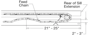
• Spinner shaft bearing (1) - Check the Feed Chain tension periodically.

To check the tension, measure in 21″-25″ from the rear edge of the gear box mount. Push up on the chain with your hand. The conveyor chain should lift up 2″-3″ off the conveyor chain guide or cross angles. - Empty the spreader of all ice control material when not in use to prevent a frozen feed chain.
- Wash out the spreader when it is not in use. At the end of the season wash out the spreader to remove all ice control materials. Thoroughly dry all metal surfaces. Paint and oil all bare metal surfaces and chains to protect from rust. Properly store the spreader for the next season.
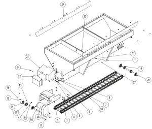
Repair Parts – Drive Subassembly
ITEM | PART NO. | QTY. | DESCRIPTION |
| 1 | 3015108 | 1 | HOPPER WELDMENT 72 SST |
| 1 | 3014321 | 1 | HOPPER WELDMENT 96 SST |
| 2 | 3013875 | 1 | MOUNT GEAR MOTOR SHE096SS |
| 3 | – | 8 | SCREW, BTN HD SOC CAP 1/2-13 X 1 SST |
| 4 | – | 8 | NUT, HX FLNG 1/2-13 X 1 SST |
| 5 | 1410241 | 1 | WIPER BELT, HOPPER |
| 6 | – | 8 | WASHER, FLAT 1/4 SAE, SST |
| 7 | – | 5 | WASHER, 1/4″ SPRING LOCK SST |
| 8 | – | 5 | NUT, HEX 1/4-20 SST |
| 9 | – | 8 | SCREW, CAP 1/4-20 X 3/4 SST |
| 10 | 3013821 | 1 | GEAR MOTOR CONVEYOR 12 VDC |
| 11 | 1410250 | 2 | SPROCKET, 6 TOOTH PINTLE CHAIN |
| 12 | KS402 | 2 | KEY, 1/4 X 1/4 X 2 |
| 13 | – | 1 | SCREW, SET 1/4-20 X 1/4 CUP POINT |
| 14 | 1410200 | 1 | BEARING, FLANGED 1-1/8″ |
| 15 | – | 2 | BOLT, 3/8 X 1 1/4, LOW HEAD |
| 16 | – | 2 | NUT, NYLOCK 3/8-16 X 7/16 SST |
| 17 | – | 4 | SCREW, HHC 3/8-16 X 1 304 SST |
| 18 | 1401300 | 1 | CHAIN, CONVEYOR, 93 LINKS |
| 18 | 1401100P | 1 | CHAIN ASSY D662 122 LINKS |
| 19 | 3008571 | 1 | SHAFT IDLER, ASSEMBLY |
| 20 | 1411001 | 2 | BEARING, IDLER TAKE UP |
| 21 | 3013898 | 1 | SHROUD GEAR MOTOR |
| 22 | 3014275 | 1 | COVER REMOVABLE |
| 23 | 3014744 | 2 | CIRCLE COTTER 1 X .060SST |
| 24 | 3014949 | 2 | SHIELD, CHAIN, 96″ |
| 24 | 3014959 | 10 | SHIELD, CHAIN 72″ |
| 25 | – | 10 | BOLT, 3/8-16 X 1 CARRIAGGE SHORT NECK SST |
| 26 | – | 10 | WASHER, FLAT 3/8 USS SST |
| 27 | – | 5 | NUT, 3/8-16 HEX SST |
| 28 | 3014778 | 1 | MOTOR REPLACEMENT FOR 3013821 |
Repair Parts – Spinner/Chute Assembly
| ITEM | PART NO. | QTY. | DESCRIPTION |
| 1 | 3017969 | 1 | CHUTE UPPER WELDMENT |
| 2 | 3016309 | 1 | MOTOR 12 VDC, .5 HP SPINNER |
| 3 | FCS038016075SS | 14 | SCREW, HHC-3/8-16 X 3/4 SST |
| 4 | 3017974 | 1 | COUPLER SHAFT ADJUSTABLE |
| 5 | 3018190 | 1 | PIN SPRING 5/16 X 1.25 SST |
| 6 | 3018106 | 1 | SHAFT CHUTE ADJUSTABLE |
| 7 | FCS031018175SS | 1 | SCREW, HHC 5/16-18 X 1 3/4 SS |
| 8 | FNE031018034SS | 3 | NUT, NYLOCK 5/16-18 SS |
| 9 | 3017970 | 1 | CHUTE LOWER WELDMENT |
| 10 | 3030680 | 1 | SPACER BEARING, LOWER CHUTE |
| 11 | 1420101 | 1 | BEARING, SPINNER SHAFT |
| 12 | FNE038016044SS | 10 | NUT, NYLOCK 3/8-16 X 7/16 SST |
| 13 | FWF038100007SS | 4 | WASHER, FLAT 3/8 USS SST |
| 14 | FCS038016100SS | 2 | SCREW, HHC 3/8-16 X 1 304 SST |
| 15 | 3027439 | 1 | 3/4 IN SHAFT SLINGER |
| 16 | 3012393 | 1 | SPINNER, 14″ POLY CW |
| 17 | 3007113 | 1 | PIN, CLEVIS, 5/16 X 2-1/2, .141 HOLE ZN |
| 18 | FPC013000100 | 1 | COTTER PIN, 1/8 X 1, ZINC |
| 19 | 3013840 | 2 | DEFLECTOR SIDE SST |
| 20 | 3018114 | 1 | DEFLECTOR REAR SST |
| 21 | 3018192 | 2 | PIN, SIDE DEFLECTOR |
| 22 | 3018193 | 1 | PIN, REAR DEFLECTOR |
| 23 | 3001257 | 6 | PIN, HAIR COTTER STAINLESS STL |
| 24 | 3018119 | 1 | INNER BAFFLE PASS SIDE WELDMENT |
| 25 | 3018120 | 1 | INNER BAFFLE DRVR SIDE WELDMENT |
| 26 | 3018189 | 1 | RETAINER, INTERNAL BAFFLES |
| 27 | 3008853 | 2 | SPRING, SPINNER CHUTE BAFFLE |
| 28 | FPC009000075SS | 2 | PIN, COTTER 3/32 X 3/4 STAINLESS |
| 29 | 3006753 | 1 | WIRE HARNESS, CHUTE |
| 30 | 3024533 | 1 | WIPER BELT, CHUTE |
| 31 | FCS025020075SS | 3 | SCREW, CAP 1/4-20 X 3/4 SST |
| 32 | FWF025063007SS | 3 | WASHER, FLAT 1/4 SAE SS |
| 33 | FCS031018063SS | 2 | SCREW, HHC 5/16-18 X 5/8 SST |
| 34 | FNE025020031SS | 3 | NUT, NYLON INSERT 1/4-20 SST |
| 35 | FWF031075006SS | 2 | WASHER, 5/16 SAE SST |

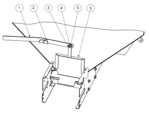
Repair Parts – Feed Gate Assembly
ITEM | PART NO. | QTY | DESCRIPTION |
| 1 | 1410108SS | 1 | FEED GATE LEVER, SST |
| 2 | 1410109SS | 1 | LEVER NUT, SST |
| 3 | 1 | BOLT CARRIAGE 3/8-16 X 1-1/4” SST | |
| 4 | 2 | 3/8 FLAT WASHER SST | |
| 5 | 1 | 3/8-16 HEX LOCKNUT SST | |
| 6 | 141010WSS | 1 | FEED GATE PANEL WELDMENT, SST |
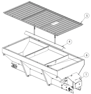
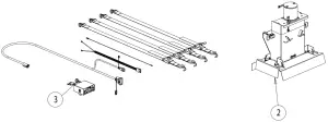
Repair Parts
ITEM | PART NO. | QTY. | DESCRIPTION |
| 1 | 30015853 | 1 | Spreader 72″ SST Unfinished |
| 1 | 3013819 | 1 | Spreader 96″ SST Unfinished |
| 2 | 3017966 | 1 | Chute Adjustable |
| 3 | 3018351 | 1 | Hardware Box 1400601SS, 1400701SS |
| 4 | 1499500SS | 1 | Vee, Assy Inverted w/HDW SST |
| 4 | 1499700SS | 1 | VEE Inverted 96″ |
| 5 | 3007349 | 1 | Screen Top, WELDM |
| 5 | 3007568 | 1 | Screen, Welded Top, SCH096 |
| 6 | 66050 | 2 | Snapper Pin, 1/4 x 2, Ylw ZN |

9049 Tyler Blvd.
• Mentor, Ohio 44060
Phone (440) 974-8888
• Fax (440) 974-0165
www.saltdogg.com


