![]()
WHST
Product Introduction
STA79-7 Electric Tail Gate Radar
PRODUCT MANUAL
WHST CO., LTD.
Factory 1, Wanchun High-tech Innovation Park, East Dist of Economic & Technological Development Zone, 241000 Wuhu, Anhui, China 2023.04
Revision record
| Date | Version | Description | Author |
| 2023-4-25 | V1.0 | Initial version | Yu Xuze |
Product Introduction
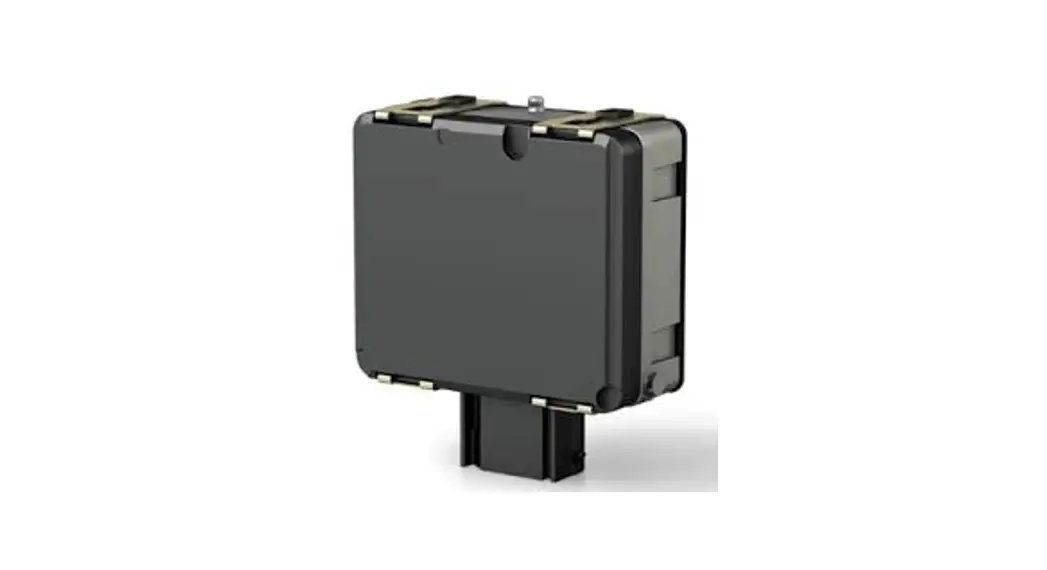
STA79-7 Radar is a 79GHz product based millimeter-wave technology independently developed by WHST. The radar can detect foot movement to open the tailgate automatically. It has the characteristics of small size, light weight and high performance.
Radar is hidden in the rear bumper with KL30 power. When the car is in standing completely still and the key is within a specific range, the radar can be triggered into detection mode. The electromagnetic wave can penetrate the guard bar to detect the movement of feet. After detecting the specific foot movement, LIN messages will be sent to master controller. Radar supports local sleep and remote wake-up.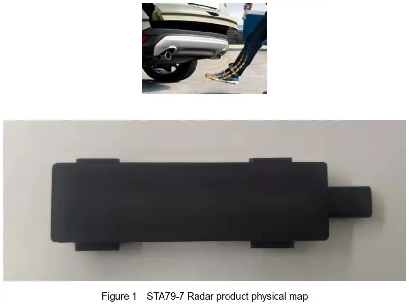
Product description
2.1 Technical index
See Table 1 for the technical indicators of STA79-7 type vehicle radar products.
Table 1. STA79-7 radar product technical indicators
| Product Features | Electric Tail Gate Radar | |
| Frequency Range | 770Hz-810Hz | |
| Modulation waveform | FMCW | |
| RF Output Power | 34.56dBm | |
| Effective bandwidth | 4GHz | |
| Data rate | 50Hz | |
| Detection Range | .‘.0.6m | |
| Velocity Range | -20m/s-1-20trils | |
| Velocity Resolution | 0.76m/s | |
| Dimensions | 107.5mm*32mm* 13.8mm | |
| Weight | -….60g | |
| Operating Voltage | 11-16V DC | |
| Quiescent Current | :-C.50uA@l2V | |
| Working Temperature | -40t —I-85t | |
| Storage Temperature | -40t–+95t | |
| Multi-ta rget different iation | Range resolution | 0.1m |
| Speed resolution | 1m/s | |
| Working current | 1-5200mA@I2V | |
| (typical value) | ||
| Power consumption | ≤2W | |
| Protection level | IP6K7 | |
| Communication port | LIN | |
Interface description
Radar equipment terminal connector and wiring harness terminal connector are shown in Figure 2, and the wiring definition is shown inTable 2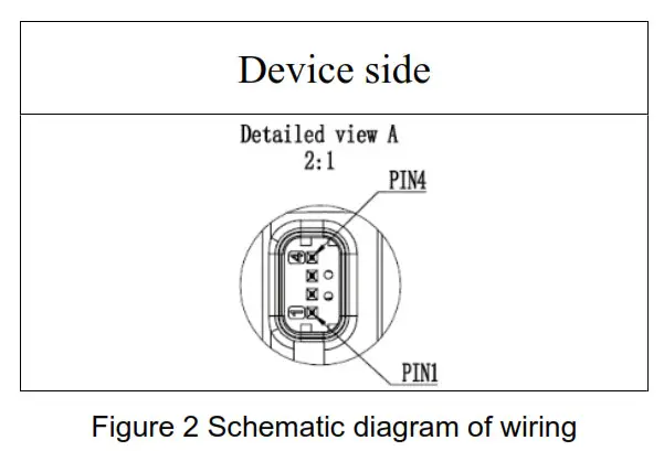
Table 2 Definition of external plug-in pins
| NO | Pin definition | Signal function | Note |
| 1 | VB AT | 9~16V | |
| 2 | NC | / | |
| 3 | LIN | I/O | |
| 4 | GND | 0V |
Radar installation method and size
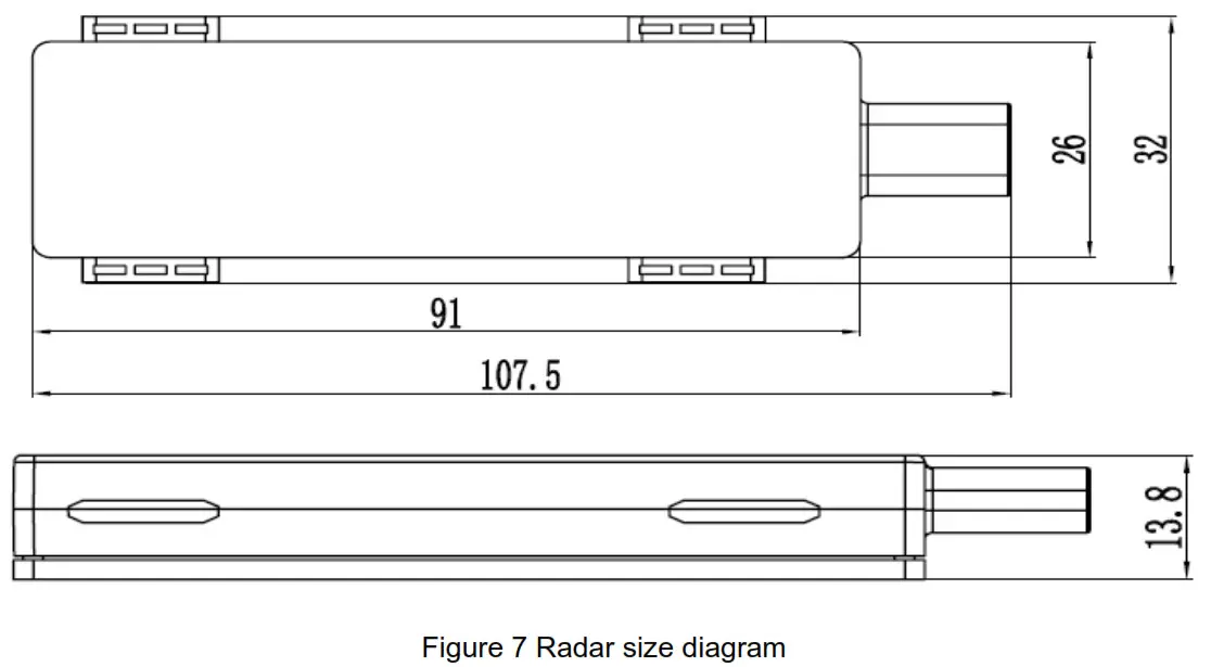
As shown in the radar size diagram in Figure 7, the product size is 106×97.8×27.3mm.
Layout principle: Based on the antenna range of 40.2*16.6mm, there should be no occlusion or molding line in the range of azimuth and pitch detection beam, and try to avoid occlusion or molding line in the range of avoidance beam. The best option is: If there is no cover in front of the radar, the following requirements must be met if the cover cannot be met:
- Uniform material, non-sandwich or mixed material;
- The cover is not allowed to contain any metal, including the metal contained in the coating of the cover;
- Spraying needs to be analyzed separately (may lead to strong radiation and attenuation);
- Shall not be perpendicular to the radar surface;
- covering material selection PP, PS, PC/PBT, PC/PET, ABS, PEI, PPS, PE;
- The attenuation (double-way loss) caused by the radar front cover (bumper, etc.) is allowed to be less than or equal to 3dB
- The curvature radius of the covering piece R ≥350mm, the special shape of the covering piece must be tested;
FCC Warning
This device complies with part 15 of the FCC Rules. Operation is subject to the following two conditions:
(1)This device may not cause harmful interference, and (2) this device must accept any interference received, including interference that may cause undesired operation. Any changes or modifications not expressly approved by the party responsible for compliance could void the user’s authority to operate the equipment. This equipment has been tested and found to comply with the limits for a Class B digital device, pursuant to part 15 of the FCC Rules. These limits are designed to provide reasonable protection against harmful interference in a residential installation. This equipment generates, uses and can radiate radio frequency energy and, if not installed and used in accordance with the instructions, may cause harmful interference to radio communications. However, there is no guarantee that interference will not occur in a particular installation. If this equipment does cause harmful interference to radio or television reception, which can be determined by turning the equipment off and on, the user is encouraged to try to correct the interference by one or more of the following measures:
—Reorient or relocate the receiving antenna.
—Increase the separation between the equipment and receiver.
—Connect the equipment into an outlet on a circuit different from that to which the receiver is connected.
—Consult the dealer or an experienced radio/TV technician for help.
FCC Radiation Exposure Statement
This equipment complies with FCC radiation exposure limits set forth for an uncontrolled environment.
This transmitter must not be co ‐located or operating in conjunction with any other antenna or transmitter.
This equipment should be installed and operated with minimum distance 20cm between the radiator& your body.


