
ABUS Nexello Bypass Opening Detector
Product launch
Scope of delivery
- ABUS Z-Wave opening detector
- 1x Duracell CR2 battery
- Assembly material: screws, dowels, adhesive pads, reset tool
- Quick guide & safety instructions
- DSK card
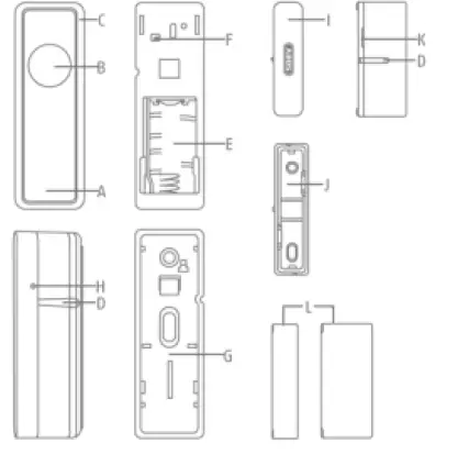
Device features
| No | Designation | Comment |
| A | Front cover | Slided onto the holder |
| B | Bypass button | Bypass function for temporary deactivation of the detector |
| C | LED indicator | Status display for various processes (Inclusion, exclusion, reset, error) |
| D | Markings | For correct alignment of sensor and magnet |
| E | Battery compartment | Observe polarity |
| F | Sabotage contact | Triggers sabotage alarm |
| G | Mounting | For mounting on the window |
| H | Link Button | Manual triggering of the wake-up command, inclusion, exclusion and reset |
| I | Front cover magnet | Contains the magnet. Must be correctly aligned with the sensor. |
| J | Holder Magnet | For mounting on the window frame |
| K | Height adjustment magnet | The magnet is extendable to compensate for small differences in height between frame and window |
| L | spacer1cm/2cm | The spacers can compensate for larger height differences between frame and window |
Operating principle
The device was developed for use in alarm and home automation systems that use the Z-Wave wireless standard. The device has the following functions:
Magnetic field sensor
It uses magnetic field sensor technology to detect whether doors or windows are open or closed in a defined area.
Bypass button
for temporary deactivation of the sensor without having to deactivate the entire alarm system. Prevents the sending of an open/close cycle or the sending of the “open” status for 5 minutes. E.g. for short bursts of ventilation or smoking on the window during internal activation. Function can be deactivated via parameter setting.
Different keystrokes can also be used for scene control.
Tamper protection between the device and wall bracket
When the housing is opened, the sabotage switch is triggered and the device sends a sabotage alarm to the Z-Wave controller
Performance features
The device..:
- … is a battery operated opening detector
- … is suitable for mounting on door/window frames due to its design
- … is Z-Wave Plus compatible & certified
- … supports the Z-Wave S2 standard (Security 2)
- … has a low battery warning function
- … was developed for indoor installation
Use in systems of different manufacturers
This product can be operated in any Z-Wave network with other Z-Wave certified devices from other manufacturers. All mains-powered nodes within the network act as repeaters, regardless of manufacturer, to increase the reliability of the network.
DSK code
The DSK code (Device-Specific-Key) is the device-specific key of your device and is required for secure teach-in (inclusion) via S2 at the gateway. The first 5 digits of the DSK code can be found on the QR Code on the side of the product. Please enter them in the inclusion process when prompted. Alternatively, you can transfer the entire DSK code that you find on the enclosed DSK card to the gateway via QR Code Scan. Please keep the DSK card in a safe place!
Hint: We recommend secure S2 inclusion (must be supported by the gateway) Please enter the 5 digits of the DSK code (device side) or the entire DSK code (QR code) when prompted.
Functional overview
Inclusion / Teach-in device
This product supports SmartStart: SmartStart-enabled products can be added to a Z-Wave network by scanning the Z-Wave QR code present on the product with a controller that provides SmartStart integration. No further action is required, and the SmartStart product will be automatically added within 10 minutes of powering up near the network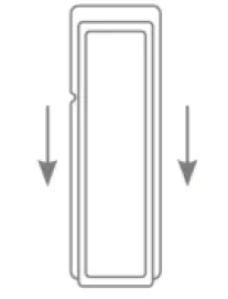
Slide the opening detector holder down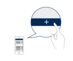 If your Z-wave controller does not support SmartStart, follow these instructions for Product
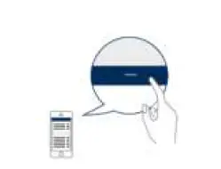
Classic Inclusion: Activate the inclusion mode (teach-in mode) on the gateway. (for more details, refer to the operating instructions of the gateway) Or, in your Z-Wave app, press the “+” button (Add / Inclusion) and follow the instructions to set the gateway to inclusion mode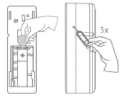
Keep the device within range of the gateway. Remove the safety strip from the battery compartment. We recommend using only the original Duracell battery supplied. Then press the Link button 3 times quickly (within 1.5
seconds) using the pin to start the inclusion on the device. The LED starts flashing green for up to 60 seconds The successful inclusion is displayed in the app or on the gateway and the status LED on the device lights green for 2 seconds. Repeat the inclusion process if it was not successful. If a new attempt fails as well, first carry out a factory reset on the device, see 2.5.
Planning, assembly and installation
The device uses low-power radio signals to communicate with the Z-Wave gateway. For best results, please note the following:
- The device has a radio range of up to 40 m.
- The battery life of the device is reduced if the wireless connection to the Z-Wave gateway is not direct but via a repeater
Assembly instructions:
- The detector is only suitable for indoor installation. The device is suitable for mounting on wood and plastic surfaces, from mounting on Metal surfaces are urgently advised against for technical reasons. Fasten the sensor holder to the window or door. Place the base on the holder.
- Fasten the holder of the magnet to the frame with the enclosed adhesive pad or screws. Place the base on the holder and, if necessary, change the height adjustment of the magnet by pulling out the grid. If necessary, use the supplied spacers to compensate for differences in height between the sensor and the magnet.
- Ensure that the sensor and magnet are aligned vertically according to the markings and that the tops are as flush as possible.
- Make sure that the horizontal distance between sensor and magnet is as small as possible, the trigger threshold is approx. 2cm.
- Make sure that the product fronts of sensor and magnet are as flush as possible, use the grids for adjusting the height of the magnet for minor adjustments and the spacers supplied for major adjustments
Exclusion / Device teach-in Activate
Activate the exclusion mode (learn mode) on the gateway. (for more details, refer to the operating instructions of the gateway) Press the “-” button (Remove / Exclusion) in your ZWave app and follow the instructions to set the gateway to Exclusion mode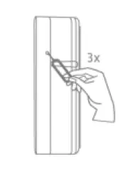 Using the pin, press the Link button 3 times quickly (within 1.5 seconds) to start the exclusion on the device. The LED starts flashing red for up to 60 seconds
 The successful exclusion is displayed in the app or on the gateway and the status LED on the device lights
Reset to factory settingsup red for 2 seconds
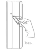
Press and hold the Link button for at least 5 seconds. Release the button when the red LED stops blinking and lights up continuously. The device is now reset to factory settings.
Hint: This procedure should only be used if the primary gateway is not capable of acting. If the device is set to factory default, the status is set to “not included” and the association settings and possible configurations are reset to default.
Wake-up / Wake up device
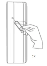
Press the Link button once to wake up the device. It will then establish a connection to the Z-Wave gateway and transmit the current status
Bypass
If the bypass button is pressed briefly once when closed, the bypass function is active. In this case, the next opening of the door/window is not sent as an opening alarm for the next 5 minutes.
- If the door or window is closed within the 5 minutes, the bypass function is reset and the next opening is reported again.
If the door or window is still open after 5 minutes, the opening detector emits an opening alarm.
The bypass function can be deactivated via the parameter setting.
Scene control
The Bypass button can distinguish between four different button presses
- Press 1x briefly
- Press 2x briefly
- Long pressure (Longer than one second)
- Release the key (only applies if the key is pressed “Long press”)
The different key presses can be used for different alarms (medical shear or panic alarm), but also for scene and home automation control
Advanced Z-Wave Parameters
Association Groups
Z-Wave devices can control other devices directly. This direct control is called association in Z-Wave. The device ID of the device to be controlled must be stored in the controlling devices. This is done in so-called association groups. An association group is always linked to an event in the controlling device (keystroke or triggering of a sensor). When this event occurs, a control command – usually a BASIC SET – is sent to all devices stored in an association group.
The device supports two association groups:
| Group- Number | Maximum Devices | Group name | Profile | command class |
| Group 1 | 5 | Lifeline | General | notification report battery report Device Reset Locally Notification Central Scene Notification |
| Group 2 | 5 | on/off control | Notification | basic set |
Group 1 (Association Z-Wave Controller)
The Lifeline Association is automatically established between the Z-Wave controller and the device during inclusion and defines what information is exchanged between the Z-Wave controller and the device.
Group 2 (direct association to terminals)
When the motion alarm is triggered, it sends a BASIC SET On / Off command to the nodes of group 2
WakeUp Time
The time between the WakeUp Notification Commands can be set in the Wakeup Command Class within the following values:
| Description | Value |
| Minimum wake-up interval | 20s |
| Maximum wake-up interval | 86400s (1 day) |
| Default value Wake-up interval | 21600s (6 hours) |
| Interval steps | 20s |
Reports
Notification report:
| Event | Type | Attribute | Parameter Length | Event Parameters |
| Opening alarm (door / window open) | 0x06 | 0x16 | ||
| Opening alarm Acknowledgement (door / window closed) | 0x06 | 0x17 | ||
| Sabotage alarm | 0x07 | 0x03 | 0x00 | |
| Sabotage alarm acknowledgement | 0x07 | 0x00 | 0x01 | 0x03 |
| Battery alarm (replace soon) | 0x08 | 0x0A | 0x00 | |
| Battery alarm (replace now) | 0x08 | 0x0B | 0x00 | |
| Battery alarm acknowledgement | 0x08 | 0x00 | 0x01 | 0x0A / 0x0B |
Battery report
| Value | Description |
| 0x05 – 0x64 (5 – 100) | Battery charge level in percent (%) |
| 0xFF (256) | Low battery |
Central Scene Report
Sent when the bypass button is pressed
| Event | Attribute | Key number |
| Press 1x briefly | 0x00 | 0x01 |
| Release (press and hold for a long time) | 0x01 | 0x01 |
| Press and hold (longer than 1s) | 0x02 | 0x01 |
| Press 2x briefly | 0x03 | 0x01 |
Overview configuration parameters
Z-Wave products can be used directly after inclusion in the network. However, configuration settings can be used to adapt the behavior of the device even better to the requirements of the application and to activate additional functions.
| Para- meter | Byte size | Function | Default value (default) | Description |
| 10 | 1 | Threshold value battery alarm | 10 | Percentage value from when the low battery alarm should be transmitted. § Adjustable from 5 – 50 in percent (Hexadecimal: 0x05 – 0x32) |
|
14 |
1 | BASIC SET to association group 2 (motion alarm) |
0 | BASIC SET should be sent after a motion alarm. § 0 = Disabled § 1 = Active (Hexadecimal: 0x00 – 0x01) |
| 15 | 1 | Invert value of BASIC SET command |
0 | Set the value of the BASIC SET command for movement alarm and acknowledgement. § 0 = The motion alarm sends the BASIC SET value “On” (0xFF), the acknowledgement sends the BASIC SET value “Off” (0x00) § 1 = The motion alarm sends the BASIC SET value “Off” (0x00), the acknowledgement sends the BASIC SET value “On” (0xFF) (Hexadecimal: 0x00 – 0x01) |
| 32 | 1 | Bypass function |
0 | Enables or disables the bypass function. § 0 = Bypass function activated § 1 = Bypass function deactivated (Hexadecimal: 0x00 – 0x01) |
Supported command classes
| Command class | Version |
| Association | Version 2 |
| Association Group Info | Version 3 |
| Battery | Version 1 |
| Central Scene | Version 3 |
| Configuration | Version 4 |
| Device Reset Locally | Version 1 |
| Firmware Update Md | Version 5 |
| Indicator | Version 3 |
| Manufacturer specific | Version 2 |
| Multi Channel Association | Version 3 |
| Notification | Version 8 |
| Power level | Version 1 |
| Security | Version 1 |
| Security 2 | Version 1 |
| Supervision | Version 1 |
| Transport Service | Version 2 |
| Version | Version 3 |
| Wake up | Version 2 |
| Z-wave Plus Info | Version 2 |
Supported security levels
- Security S2 Authenticated
- Security S2 Unauthenticated
- Security S0 Authenticated
Technical data
| Parameters | PLMK10100 |
| Dimensions (W x H x D) | 90 x 61 x 42,5 mm |
| Weight | 59 g |
| Operating temperature | >0° – 40°C |
| IP class | IP 20 (indoor area) |
| Radio frequency | 868.42 MHz (Z-Wave Plus, European) |
| Modulation | FSK (BFSK/GFSK) |
| Transmitting power: | < = 5 dbm |
| Power supply | 3 V DC |
| Type of battery | 1x CR2 |
| Battery life | ~2 years |
| Sabotage protection | Yes |
| Firmware updateable | Yes, OTA |
| Z-Wave manufacturer ID | 0x0403 |
| Z-Wave Product Type ID | 0x0002 |
| Z-Wave Device ID | 0x0006 |
| Z-Wave Beaming supported | No |
| Z-Wave SmartStart supported | Yes |
| Z-Wave Plus supported | Yes |
| Z-Wave Network Security | Yes |
| Z-Wave AES-128 Security (S0) | Yes |
| Z-Wave S2 Security | Yes (S2 Authenticated) |
| Z-Wave Chip Generation | 700 |
![]()


