![]() Connect Core MP15
Connect Core MP15
Development Board
Hardware Reference Manual
Connect Core MP15 Development Board
Revision history—90002511
| Revision | Date | Description |
| 1P | Dec-22 | Initial draft. |
Trademarks and copyright
Digi, Digi International, and the Digi logo are trademarks or registered trademarks in the United States and other countries worldwide. All other trademarks mentioned in this document are the property of their respective owners.
© 2022 Digi International Inc. All rights reserved.
Disclaimers
Information in this document is subject to change without notice and does not represent a commitment on the part of Digi International. Digi provides this document “as is,” without warranty of any kind, expressed or implied, including, but not limited to, the implied warranties of fitness or merchantability for a particular purpose. Digi may make improvements and/or changes in this manual or in the product(s) and/or the program(s) described in this manual at any time.
Warranty
To view product warranty information, go to the following website: www.digi.com/howtobuy/terms
Customer support
Gather support information: Before contacting Digi technical support for help, gather the following information:
- Product name and model
- Product serial number (s)
- Firmware version
- Operating system/browser (if applicable)
- Logs (from time of reported issue)
- Trace (if possible)
- Description of issue
- Steps to reproduce
Contact Digi technical support: Digi offers multiple technical support plans and service packages.
Contact us at +1 952.912.3444 or visit us at www.digi.com/support.
Feedback
To provide feedback on this document, email your comments to [email protected]
Include the document title and part number (Connect Core MP15 Development Board, 90002511 1P) in the subject line of your email.
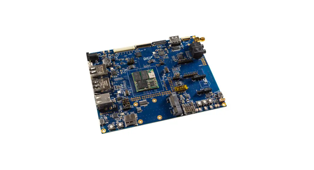
About the Connect Core MP15
The Digi Connect Core® MP15 development kit and System-on-Module (SOM) platform is a highly integrated, cost-effective, connected, secure embedded solution, built on the STM32MP15x MPU family. It integrates memory, power management, the Digi Microcontroller Assist™, pre-certified wireless connectivity and advanced Digi Trust Fence device security with a complete, open-source Linux software platform based on the Yocto Project.
Note While the Connect Core MP15 system-on-module is designed to be used in a production environment, the Connect Core MP15 Development Kit is designed only for development and testing in a pre-production environment.
Features and functionality
- ConnectCore MP15 module
- STM32MP157C dual ARM Cortex-A7 and single Cortex-M4 cores operating at speeds up to 800MHz
- Up to 1 GB, 16-bit DDR3 memory
- Up to 1 GB, 8-bit SLC NAND flash memory
- IEEE 802.11 a/b/g/n/ac WLAN and Bluetooth 5.0
- Power
- Power jack or industrial-dedicated 5V power connector
- Coin-cell battery charger, supplying the on-module RTC
- Power and reset buttons
- Boot source configuration
- NAND, USB, microSD
- Debug
- Standard IEEE 1149.1 JTAG interface
- Serial console at AB-type micro-USB connector and TTL level n Multimedia
- MIPI DSI display
- HDMI display (through MIPI-to-HDMI transceiver)
- Parallel 24-bit LCD interface with FFC on-board connector
- LVDS interface with up to four differential data pairs (through parallel-to-LVDS transceiver)
- 8-bit parallel camera
- Audio CODEC with the following functionality
o One 3.5 mm headphone jack
o One 3.5 mm microphone jack
o Two speaker outputs
o One line-out output
o Two line-in inputs
- Storage
- NAND flash
- microSD card slot
- Communication
- RS-232
- RS-485
- Two CAN
- Gigabit Ethernet
- Two USB Host 2.0 interfaces through a stacked USB A type connector
- USB OTG with AB-bye micro-USB connector
- SISO IEEE 802.11 a/b/g/n/ac + Bluetooth 5.0 with on-module U.FL or external SMA antenna connector
- PCI Express Mini Card slot supporting full and half-size cards
- Mikro Bus socket
- XBee socket supporting XBee Cellular
- User interface
- Three user LED, two of them shared with user buttons
- Dimensions:
- 120 x 160 mm
Safety instructions
- The ConnectCore MP15 development board development board cannot be guaranteed operation due to the radio link and so should not be used for interlocks in safety critical devices such as machines or automotive applications.
- The ConnectCore MP15 development board development board has not been approved for use in (this list is not exhaustive):
- nuclear applications
- explosive or flammable atmospheres
- There are no user serviceable components inside the ConnectCore MP15 development board development board. Do not modify the Connect Core MP15 development board in any way. Modifications may exclude the development board from any warranty and can cause the
Connect Core MP15 development board to operate outside of regulatory compliance for a given country, leading to the possible illegal operation of the radio. - Use industry standard ESD protection when handling the ConnectCore MP15 development board development board.
- Take care while handling to avoid electrical damage to the PCB and components.
- Do not expose Connect Core MP15 development board development board to water or moisture.
- Use this product with the antennas specified in the ConnectCore MP15 development board development board user guides.
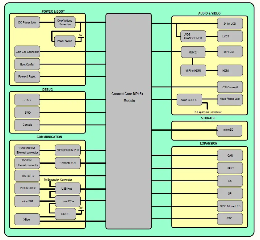
Block diagram
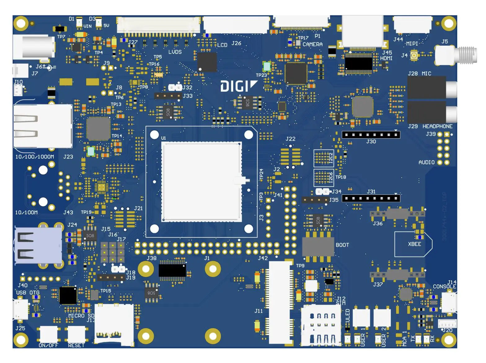
Placement
Top view
Bottom view
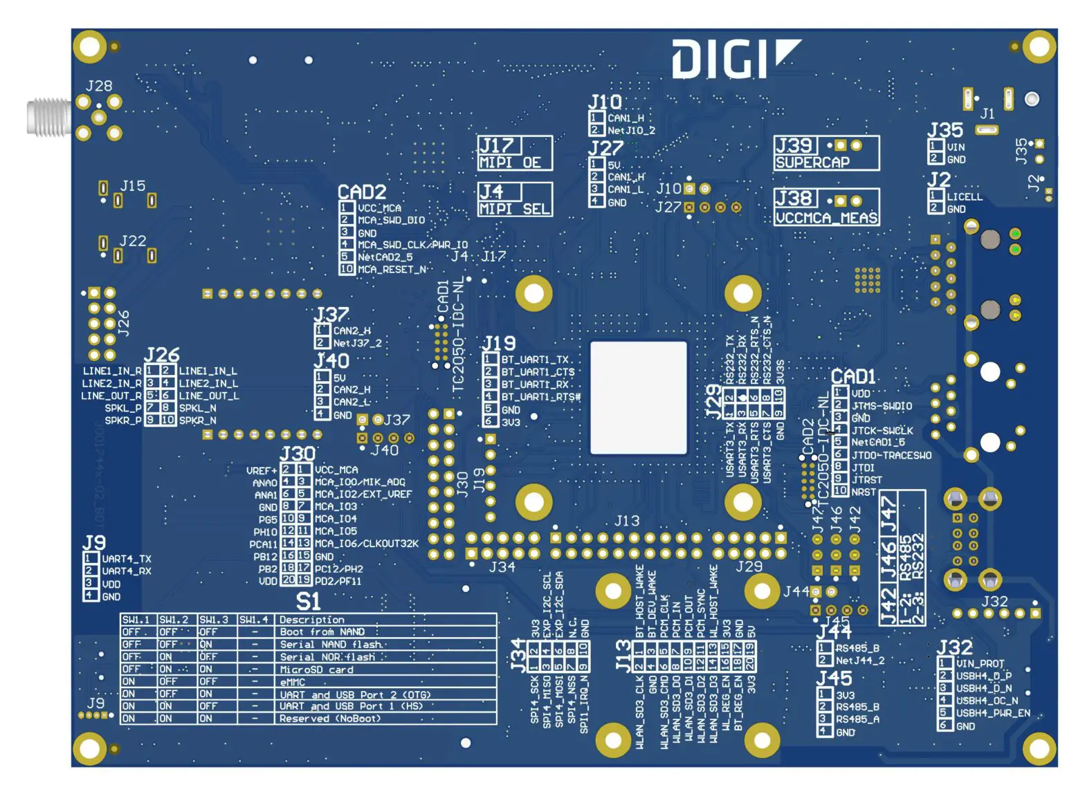
Note Serigraphy on the bottom side of the PCB is incorrect. Refer to schematics and CAD documentation for correct identification of the connectors.
Connectors
The following table lists all connectors on the Connect Core MP15 development board:
| Connector | Interface |
| J1 | WLAN/Bluetooth expansion |
| J2 | upfill |
| J3 | Bluetooth UART |
| J4 | upfill |
| J5 | SMA |
| J6 | 5V power-in jack |
| J7 | 5V power in |
| J8 | VCC_MCA series jumper |
| J9 | Supercar series jumper |
| J10 | Coin cell |
| J11 | Mini PCIe |
| J12 | Micro SIM |
| J13 | microSD |
| J14 | USB Console |
| J15 | RS232/RS485 TX line selector jumper |
| J16 | RS232/RS485 RX line selector jumper |
| J17 | RS232/RS485 RTS line selector jumper |
| J18 | RS485 termination resistor jumper |
| J19 | RS485 |
| J20 | TTL Console |
| J21 | STM32MP15 JTAG |
| J22 | MCA SWD |
| J23 | 10/100/1000 MPs RJ-45 |
| J24 | Dual USB A-type |
| J25 | USB OTG |
| J26 | Parallel display |
| J27 | LVDS display |
| J28 | Microphone jack |
| J29 | Headphone jack |
| J30-J31 | Micro Bus socket |
| J32 | CAN1 termination resistor jumper |
| J33 | CAN1 |
| J34 | CAN2 termination resistor jumper |
| J35 | CAN2 |
| J36-J37 | XBee socket |
| J38 | UART/RS232 expansion |
| J39 | Audio expansion |
| J40 | USB expansion |
| J41 | GPIO expansion |
| J42 | SPI/I2C expansion |
| J44 | MIPI display |
| J45 | HDMI |
| P1 | Parallel camera |
| S1 | Boot switches |
| SW1 | Power button |
| SW2 | Reset button |
| SW3 | User button |
| SW4 | User button |
| SW5 | User button |
| CAD1 | STM32MP1 JTAG Tag Connect |
| CAD2 | MCA SWD Tag Connect |
Interfaces
The following interfaces are available on the ConnectCore MP15 development board:
Power interfaces
This section describes the Connect Core MP15 development board power interfaces.
DC-in jack connector
The input voltage of the Connect Core MP1 Development Board is 5V. This input power supply can be provided from two different connectors:
- DC-in power jack.
- J7, a 2-pin, 2.54 mm pitch connector:
| Pin | Signal name | Description |
| 1 | VIN | 5V power supply |
| 2 | GND |
Note Digi recommends not powering both connectors at the same time.
An overvoltage circuit protects the board from overvoltage and overcurrent events. Downstream from these input power protections, there are two regulators/switches for powering the carrier board circuitry:
- 5V Load switch (U6): A 5V load switch that controls the power delivery to different interfaces on the carrier board.
- PCIe regulator (U7): A dedicated adjustable regulator for the PC I.e. socket.
Coin cell connector
Connector J10 on the board is included for attaching an external coin-cell to the system:
| Pin | Signal name | Description |
| 1 | VCC_LICELL | Power supply for RTC |
| 2 | GND |
Power and reset buttons
One power button (SW1) and one reset button (SW2) are included on the development board.
System boot
The Connect Core MP1 module supports different boot modes (see the Connect Core MP1 System-on Module Hardware Reference Manual for detailed information). The development board supports these boot modes, although some of them require changes to the populated components. A quadruple switch (S1) allows swapping between eight different boot modes:
| S1.1 | S1.2 | S1.3 | Boot mode |
| Open | Open | Open | On-module NAND |
| Open | Open | Close | Serial NAND flash |
| Open | Close | Open | Serial NOR flash |
| Open | Close | Close | MicroSD card |
| Close | Open | Open | eMMC |
| Close | Open | Close | UART and USB Port 2 |
| Close | Close | Open | UART and USB Port 1 |
| Close | Close | Close | Reserved |
Debug interfaces
JTAG
The ConnectCore MP15 Development Board provides a Tag Connect footprint for accessing the STM32MP1 JTAG debug port. Additionally, a standard 10-pin, 1.27mm pitch connector (J21) is available for accessing the JTAG interface:
| Pin | Signal name | Description |
| 1 | VDD | 3.3V Power supply |
| 2 | JTMS-SWDIO | Mode select line |
| 3 | GND | |
| 4 | JTCK-SWCLK | Clock line |
| 5 | GND | |
| 6 | JTDO-TRACESWO | Data output line |
| 7 | NC | |
| 8 | JTDI | Data inputs line |
| 9 | GND | |
| 10 | NRST | Reset line of the CPU |
Console port
A dedicated USB micro AB-type port (J14) provides access to the console port of the ConnectCore MP1 system-on-module. This USB port is routed directly to the CY7C65211 bridge, which converts the USB bus into TTL level. UART4 is used as the console debug port of the STM32MP1 CPU. This UART can also be accessed directly at TTL level through J20 connector:
| Pin | Signal name | Description |
| 1 | UART4_TX | UART transmission line |
| 2 | UART4_RX | UART receiver line |
| 3 | VDD | 3.3V Power supply |
| 4 | GND |
Default console port settings:
- Baud rate: 115200
- Data: 8 bit
- Parity: none
- Stop: 1 bit
- Flow control: none
Multimedia
Parallel/LVDS display
The ConnectCore MP15 provides a 24-bit RGB LCD interface available through a 40-pin, 0.5 mm pitch, FFC connector. Backlight control signal, I2C port, and interrupt line for the touch screen panel are available on the LCD connector.
The following table shows the pinout of the parallel display connector (J26):
| Pin | Signal name | Description |
| 1 | GND | |
| 2 | LTDC_B2 | Blue 2 data line |
| 3 | LTDC_B3 | Blue 3 data line |
| 4 | LTDC_B4 | Blue 4 data line |
| 5 | LTDC_B5 | Blue 5 data line |
| 6 | LTDC_B6 | Blue 6 data line |
| 7 | LTDC_B7 | Blue 7 data line |
| 8 | LTDC_G2 | Green 2 data line |
| 9 | LTDC_G3 | Green 3 data line |
| 10 | LTDC_G4 | Green 4 data line |
| 11 | LTDC_G5 | Green 5 data line |
| 12 | LTDC_G6 | Green 6 data line |
| 13 | LTDC_G7 | Green 7 data line |
| 14 | LTDC_R2 | Red 2 data line |
| 15 | LTDC_R3 | Red 3 data line |
| 16 | LTDC_R4 | Red 4 data line |
| 17 | LTDC_R5 | Red 5 data line |
| 18 | LTDC_R6 | Red 6 data line |
| 19 | LTDC_R7 | Red 7 data line |
| 20 | LTDC_B0 | Blue 0 data line |
| 21 | LTDC_B1 | Blue 1 data line |
| 22 | LTDC_G0 | Green 0 data line |
| 23 | LTDC_G1 | Green 1 data line |
| 24 | LTDC_R0 | Red 0 data line |
| 25 | LTDC_R1 | Red 1 data line |
| 26 | GND | |
| 27 | LTDC_CLK | Display clock line |
| 28 | GND | |
| 29 | LTDC__HSYNC | Horizontal sync line |
| 30 | LTDC__VSYNC | Vertical sync line |
| 31 | LTDC_DE | |
| 32 | LTDC__RESET | |
| 33 | LTDC_I2C_SCL | STM32MP1 I2C2 bus clock line |
| 34 | LTDC_I2C_SDA | STM32MP1 I2C2 bus data line |
| 35 | LTDC_IRQ_N | Interrupt line |
| 36 | GND | |
| 37 | BCKL_PWM | Backlight PWM |
| 38 | 3V3 | 3.3V power supply |
| 39 | 5V_DISPLAY | 5V power supply |
| 40 | 5V_DISPLAY | 5V power supply |
This same parallel display bus is connected to a parallel-to-LVDS transceiver, allowing support for LVDS displays through a 20-pin, 1.25 mm pitch connector (J27). This means that parallel and LVDS connectors cannot be used simultaneously.
This LVDS connector also provides backlight control signal, I2C port, and an interrupt line for the touch screen panel:
| Pin | Signal name | Description |
| 1 | 3V3 | 3.3V power supply |
| 2 | LVDS0_TX0_N | Transmission pair data line 0 (-) |
| 3 | LVDS0_TX0_P | Transmission pair data line0 (+) |
| 4 | GND | |
| 5 | LVDS0_TX1_N | Transmission pair data line 1 (-) |
| 6 | LVDS0_TX1_P | Transmission pair data line 1 (+) |
| 7 | GND | |
| 8 | LVDS0_TX2_N | Transmission pair data line 2 (-) |
| 9 | LVDS0_TX2_P | Transmission pair data line 2 (+) |
| 10 | GND | |
| 11 | LVDS0_CLK_N | Transmission pair clock line (-) |
| 12 | LVDS0_CLK_P | Transmission pair clock line (+) |
| 13 | GND | |
| 14 | LVDS0_TX3_N | Transmission pair data line 3 (-) |
| 15 | LVDS0_TX3_P | Transmission pair data line 3 (+) |
| 16 | BCKL_PWM | Backlight PWM |
| 17 | LTDC_I2C_SCL | STM32MP1 I2C2 bus clock line |
| 18 | LTDC_I2C_SDA | STM32MP1 I2C2 bus data line |
| 19 | LCD_IRQ_N | Interrupt line |
| 20 | 5V_DISPLAY | 5V power supply |
MIPI/HDMI display
The ConnectCore MP1 system-on-module supports only one MIPI-DSI display interface. On the development board, this MIPI-DSI display is managed so that two different display interfaces are supported, although only one of them can work at a time:
- HDMI: The Lontium LT8912B bridge is populated on the development board to adapt the MIPIDSI interface to HDMI. This HDMI interface is available over a standard HDMI connector.
- MIPI-DSI: the native MIPI-DSI interface of the SOM is available over a 20-pin connector (J44):
| Pin | Signal name | Description |
| 1 | DSI_DA0_P | Data pair 0 (+) line |
| 2 | DSI_DA0_N | Data pair 0 (-) line |
| 3 | GND | |
| 4 | DSI_DA1_P | Data pair 1 (+) line |
| 5 | DSI_DA1_N | Data pair 1 (-) line |
| 6 | GND | |
| 7 | NC | |
| 8 | NC | |
| 9 | GND | |
| 10 | NC | |
| 11 | NC | |
| 12 | GND | |
| 13 | DSI_CKA_P | Clock pair (+) line |
| 14 | DSI_CKA_N | Clock pair (-) line |
| 15 | GND | |
| 16 | LTDC_I2C_SCL | STM32MP1 I2C2 bus clock line |
| 17 | LTDC_I2C_SDA | STM32MP1 I2C2 bus data line |
| 18 | BCKL_PWM | Backlight PWM |
| 19 | GND | |
| 20 | 3V3 | 3.3 V power supply |
Parallel camera
The Connect Core MP15 Development Board provides a parallel camera sensor interface (CSI), available over a 30-pin, 0.5 mm pitch FFC connector (P1):
| Pin | Signal name | Description |
| 1 | GND | |
| 2 | NC | |
| 3 | NC | |
| 4 | DCMI_D0 | Camera data line 0 |
| 5 | DCMI_D1 | Camera data line 1 |
| 6 | DCMI_D2 | Camera data line 2 |
| 7 | DCMI_D3 | Camera data line 3 |
| 8 | DCMI_D4 | Camera data line 4 |
| 9 | DCMI_D5 | Camera data line 5 |
| 10 | DCMI_D6/FDCAN1/2_RX | Camera data line 6 |
| 11 | DCMI_D7/FDCAN1/2_TX | Camera data line 7 |
| 12 | NC | |
| 13 | NC | |
| 14 | GND | |
| 15 | DCMI_PIXCLK | Camera pixel clock line |
| 16 | GND | |
| 17 | DCMI_HSYNC | Camera horizontal sync |
| 18 | 5V | 5V power supply |
| 19 | DCMI_VSYNC | Camera vertical sync |
| 20 | 3V3 | 3.3V power supply |
| 21 | CAMERA_CLK | Camera master clock line |
| 22 | NC | |
| 23 | GND | |
| 24 | NC | |
| 25 | CAM_GPIO | Camera dedicated GPIO |
| 26 | CAM_PWDN | Camera power down line |
| 27 | DCMI_I2C_SDA | STM32MP1 I2C2 bus dataline |
| 28 | DCMI_I2C_SCL | STM32MP1 I2C2 bus clock line |
| 29 | GND | |
| 30 | 3V3 | 3.3 V power supply |
Audio
The Maxim MAX98089 audio codec manages the audio interface on the development board. The board provides the following audio functionality:
- 3.5 mm headphone jack
- 3.5 mm microphone jack
- x2 speaker outputs (left and right)
- x1 line-out output
- x2 line-in inputs
The speakers, line-out signals and line-in signals are available over a 10-pin connector (J39):
| Pin | Signal name | Description |
| 1 | LINE1_IN_R | Single-ended line input A1 |
| 2 | LINE1_IN_L | Single-ended line input A2 |
| 3 | LINE2_IN_R | Single-ended line input B1 |
| 4 | LINE2_IN_L | Single-ended line input B2 |
| 5 | LINE_OUT_R | Right line output |
| 6 | LINE_OUT_L | Left line output |
| 7 | SPKL_P | Positive left-channel class D speaker output |
| 8 | SPKL_N | Negative left-channel class D speaker output |
| 9 | SPKR_P | Positiveright-channel class D speaker output |
| 10 | SPKR_N | Negative right-channel class D speaker output |
Storage interface
MicroSD
A microSD socket connected to the SDMMC2 port of the STM32MP1 CPU is available on the Connect Core MP15 development board.
Communication
Gigabit Ethernet
10Base-T/100Base-Tx/1000Base-T Ethernet interface is fully integrated in the board through the Analog Devices ADIN1300 Ethernet PHY. The Ethernet interface is accessible through a RJ-45 connector with integrated link/activity LEDs.
UART/RS-232/RS-485
RS-232 and RS-485 standards are supported on the Connect Core MP15 Development Board, by sharing one CPU UART port (UART7). This means that only one of the two protocols can be use at a time. Selection between both is done through three three-position headers (J15, J16 and J17). RS-232 port is available in connector J38, where USART3 is also connected:
| Pin | Signal name | Description |
| 1 | USART3/8_TX | UART3 transmission line |
| 2 | RS232_7_TX | RS232 transmission line |
| 3 | USART3/8_RX | UART3 receiver line |
| 4 | RS232_7_RX | RS232 receiver line |
| 5 | USART3/8_RTS | UART3 RTS line (output) |
| 6 | RS232_7_RTS_N | RS232 RTS line (output) |
| 7 | USART3/8_CTS | UART3 CTS line (input) |
| 8 | RS232_7_CTS_N | RS232 CTS line (input) |
| 9 | GND | |
| 10 | 3V3 | 3.3 V power supply |
Note USART3 interface is shared with XBee socket and CAN.
RS-485 is on J19:
| Pin | Signal name | Description |
| 1 | 3V3 | 3.3 V power supply |
| 2 | RS485_B | RS485 B line |
| 3 | RS485_A | RS485 A line |
| 4 | GND |
CAN
Two CAN FD buses are available on the development board through connectors J33 (CAN1) and J35 (CAN2). The pinout of these connectors is as follows, where x refers to the CAN interface on each connector:
| Pin | Signal name | Description |
| 1 | 5V | 5V power supply |
| 2 | CANx_H | CAN high line |
| 3 | CANx_H | CAN low line |
| 4 | GND |
You can connect 120Ω terminator resistors to each port by closing J32 (CAN1) and J34 (CAN2).
Note The CAN1 interface is shared with parallel camera and CAN2 interface is shared with XBee socket USART3.
USB Host
The ConnectCore MP15 Development Board offers support for four USB Host interfaces. Two of them are available over a stackable dual USB A-type connector. The third USB Host is connected to the PCI Express Mini card connector. The fourth is connected to the XBee socket as well as to a a 6-pin, 1.25 mm pitch expansion connector (J40). All USB Hosts can operate at full, high, and low speed. The following table shows the pinout of the USB expansion connector:
| Pin | Signal name | Description |
| 1 | VIN_PROT | 5V power supply |
| 2 | USBH4_D_P | USB 4 differential data signal (+) |
| 3 | USBH4_D_N | USB 4 differential data signal (-) |
| 4 | USBH4_OC_N | Over current input |
| 5 | USBH4_PWR_EN | Power enable output |
| 6 | GND |
USB OTG
A micro-AB type receptacle for USB OTG connection is available on the Connect Core MP15 Development Board. This interface can operate in both Host and Device mode.
High-speed, full-speed, and low-speed connections are supported in Host mode. High-speed and full speed connections are supported in Device mode.
Mini PCI Express slot
The Connect Core MP15 Development Board provides a Mini PCI Express socket supporting USB and I2C connection to the CCMP15 module. A micro SIM socket is also connected to the Mini PCI Express slot.
XBee socket
One XBee socket is populated on the development board, supporting XBee Cellular modules. The UART bus connected to the XBee socket (USART3) is shared with CAN2.
Mikro Bus socket
The Connect Core MP1 Development Board provides a socket compatible with Mikro Electronica Micro Bus click boards, supporting I2C, UART, SPI, ADC and PWM connectivity.
SPI and I2C
A expansion connector provides access to one SPI interface (shared with the Mikro Bus socket) and the I2C2 bus:
| Pin | Signal name | Description |
| 1 | SPI4_SCK | SPI clock line |
| 2 | 3V3 | 3.3V Power supply |
| 3 | SPI4_MISO | SPI MISO line |
| 4 | EXP_I2C_SCL | STM32MP1 I2C2 bus clock line |
| 5 | SPI4_MOSI | SPI MOSI line |
| 6 | EXP_I2C_SDA | STM32MP1 I2C2 bus data line |
| 7 | SPI4_NSS | SPI slave select line |
| 8 | NC | |
| 9 | SPI1_IRQ_N | Interrupt line/GPIO |
| 10 | GND |
GPIO
An additional expansion connector provides access to different IOs for general purpose usage:
| Pin | Signal name | Description |
| 1 | VCC_MCA | MCA power supply |
| 2 | VREF+ | STM32MP1 internal ADC/DAC reference voltage |
| 3 | MCA_IO0/MIK_ADC | MCA IO |
| 4 | ANA0 | STM32MP1 ADC |
| 5 | MCA_IO2/EXT_VREF | MCA IO |
| 6 | ANA1 | STM32MP1 ADC |
| 7 | MCA_IO4 | MCA IO |
| 8 | GND | |
| 9 | MCA_IO5 | MCA IO |
| 10 | NU | Not used on MP15 |
| 11 | MCA_IO6/CLKOUT32K | MCA IO and 32 kHz output clock |
| 12 | NU | Not used on MP15 |
| 13 | MP15_PF15 | STM32MP1 IO |
| 14 | NU | Not used on MP15 |
| 15 | NU | Not used on MP15 |
| 16 | NU | Not used on MP15 |
| 17 | NU | Not used on MP15 |
| 18 | NU | Not used on MP15 |
| 19 | NU | Not used on MP15 |
| 20 | NU | Not used on MP15 |
User interfaces
Three LEDs are available on the development board, all of them are connected to CPU GPIOs. Two of them are shared with user buttons
Wireless
There is a u.FL connector (J4) which is routed directly to a SMA connector (J5). The purpose is to addapt the u.FL form factor to SMA form factor in order to extend the number of antennas that can be used on the development board for either the on-module antenna path or any other RF path that could be used on a PCIe or XBee board.
Specifications
Electrical specification
Supply voltages
The Connect Core MP15 Development Board has three supply inputs. Two of them power the whole system (Connect Core MP15 Development Board plus the Connect Core MP15 system-on-module) and the other one powers the RTC of the module when the main supply is not present. The following table shows the voltage range of the input supplies of the Connect Core MP15 Development Board:
| Signal | Description | Min | Typ | Max | Unit |
| VIN (jack connector) | Power jack input | 4.6 | 5.0 | 5.5 | V |
| VIN (additional connector) | Additional connector input | 4.6 | 5.0 | 5.5 | V |
| VCC_LICELL | Supply for RTC | 1.1 | 5.5 | V |
Power consumption
The power consumption of the entire board (the ConnectCore MP15 Development Board plus the ConnectCore MP15 module) has been measured directly through the 5V input power supply. The following table lists power consumption figures measured in the ConnectCore MP15 Development Board under specific use cases.
| Development board power consumption (VIN) | |||||
| Suspend mode | Power-off mode | Run-time | |||
| IDLE | Display connected (IDLE) | Decoding video | CPU stress | ||
| 40 mW | 2 mW | 0.84 W | 2.85 W | 3.10 W | 1.375 W |
Note To better understand the power consumption of the system, refer to the Connect Core MP1 System-on-Module Hardware Reference Manual to see the power consumption of the module (isolated) under the same use cases.
Use case descriptions
This section describes the use cases that were used to measure power consumption of the ConnectCore MP15 Development Board.
Suspend
System in suspend to RAM mode.
![]() CAUTION! You can achieve minimum power consumption numbers by disabling both 3.3V power domains. However, in some applications it may not be possible to switch them off, depending on what they are powering.
CAUTION! You can achieve minimum power consumption numbers by disabling both 3.3V power domains. However, in some applications it may not be possible to switch them off, depending on what they are powering.
Power-off
System in power-off with RTC enabled.
IDLE
System up and running. Ethernet and wireless disabled.
Decoding video
System up and running with the following configuration:
- Ethernet and wireless disabled.
- Fusion7 parallel display connected to the system.
Includes two different use cases:
- Display connected in IDLE mode (without decoding video).
- CPU decoding video.
CPU stress
System up and running with the following configuration:
- One Ethernet interface up and linked. The other one disabled.
- USB connected to the system.
- Hanoi application running (Hanoi application stresses the CPU and put it at 100% work load).
Mechanical specification
The ConnectCore MP15 Development Board dimensions are 120 x 160 mm. Four 3.2mm drills are located on the four corners of the PCB for assembling the board into an enclosure. These drills have a 5.5mm round metalized area for the screws and nuts. The board has four 2.6mm drills to assembly a half size or a full size PCI express mini card module, with 5.8mm x 5.8mm square metalized area for the screws and nuts.
Environmental specification
| Specification | Operating temperature |
| Industrial | -40° C to +85° C |
WLAN specification
For a complete WLAN specification, refer to the Connect Core MP1 System-on-Module Hardware
Reference Manual.
Connect Core MP15 Development Board


