JDV3-JDV4 10LI Commercial Finned Tube Radiation
Product Information: DURA-VANE II COMMERCIAL FINNED TUBE
RADIATION JDV3/JDV4 10LI VJDV10-II-2
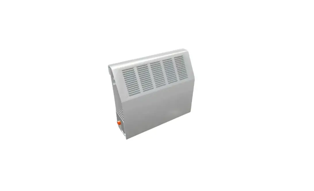
The DURA-VANE II is a commercial finned tube radiation system
used for heating purposes. It consists of an extruded aluminum
floor angle, heating element, enclosure, valve compartments, and
overlapping accessories. The backplate is mounted to the wall at
the prescribed height and is available in full or partial size. The
enclosure grille engages directly into the backplate’s ‘V’ bend.
The posi-loc clamps are used to secure the enclosure.
Product Usage Instructions:
- Refer to the submittal drawing to determine the prescribed
height for mounting the backplate on the wall. Ensure that it is
straight and level. If valve compartments are being used, make sure
that an equivalent amount of backplate is installed. - Install the extruded aluminum floor angle to the floor at the
location shown on the submittal drawing. It should run the full
length of the run, including enclosure and accessories. - Lay out the heating element as required. Place the slide cradle
onto the bottom of the element at each bracket location. The
element cradle has two legs that angle out slightly. Position the
legs between the fins so there is tension against the legs. This
holds the cradle in position. Check the submittal drawing for the
correct position of the element fin. For copper tube elements,
flush the loop or series with system water after soldering to
neutralize the remaining flux material and prevent corrosive action
and resulting pinhole leaks. - Install the enclosure grille starting at the left end of the
run, working clockwise. Tap the alignment pin into the left front
end of the grille. The rear of the enclosure grille engages
directly into the ‘V’ bend of the backplate. Firmly push the next
piece of cover into slip joint tabs and alignment pin of the piece
on the left until the run is completed. Secure the bottom of the
enclosure into brackets and tighten the posi-loc clamps to secure
the enclosure. - Install overlapping accessories as indicated on the room
schedule. All accessories are overlapping. Valve compartments are
installed the same as the enclosure. The top back bend is slipped
between the wall and the backplate. The accessory bottom will be
secured to the enclosure with fasteners supplied by others.
INSTALLATION INSTRUCTIONS
DURA-VANE II
COMMERCIAL FINNED TUBE RADIATION JDV3/JDV4 10LI
VJDV10-II-2
1. Determine quantities of enclosure and accessories required per wall or run. If installation is wall-to-wall, run backplate to within ½” of adjoining wall(s). If run ends with end cap, extend backplate beyond end of required enclosure 1-1/2″ for 4″ end and 6″ for 8-3/8″ end.
2. Mount backplate (full or partial) to wall at prescribed height (Refer to Submittal Drawing) making sure that it is straight and level. If valve compartments are being used, make sure that an equivalent amount of backplate is installed.
3. Install extruded aluminum floor angle to the floor at the location shown on submittal drawing. The floor angle will run the full length of the run including enclosure and accessories.
4. Hot Water Systems or Steam Systems (Two Pipe): Wall mounted hangers are required to support the element only. Hot water systems do not require pitch for the element. Install two (2) wall mounted hangers per element length up to 6′-0″ of length. Use three (3) wall mounted hangers per element length 6′-6″ up to 12′-6″ (8′-0″ for ¾” copper/aluminum) of length. (Accessories do not require brackets). Secure hangers to wall using fasteners (as specified) by others. For two pipe steam systems, the wall mounted hangers must be located so the supply end starts at the highest point and pitches down at a rate of ½ inch per 20 foot run.
5. Lay out heating element as required. Place slide cradle onto the bottom of element at each bracket location. The element cradle has two legs that angle out slightly. Position the legs between the fins so there is tension against the legs. This holds
the cradle in position. Check submittal drawing for correct position of element fin. For copper tube elements, flush the loop or series with system water after soldering to neutralize the remaining flux material and prevent corrosive action and resulting pinhole leaks.
6. The enclosure can now be installed. Start enclosure at left end of run working clockwise. Tap alignment pin into left front end of grille. The rear of the enclosure grille engages directly into the `V’ bend of the backplate. Firmly push next piece of cover into slip joint tabs and alignment pin of piece on left until run is completed. Secure bottom of enclosure into brackets. Tighten the posi-loc clamps to secure the enclosure.
7. Install overlapping accessories as indicated on room schedule. All accessories are overlapping. Valve Compartments are installed the same as enclosure. The top back bend is slipped between the wall and the backplate. The accessory bottom will be secured to the enclosure with fasteners supplied by others.
MAINTENANCE Before each heating season, remove accessories and enclosure panel to inspect finned tube elements for accumulation of dust or other debris that may accumulate and block airflow between fins. Remove dust and debris from coil fins with a vacuum cleaner or compressed air. Inspect for leaks or areas of corrosion. It should not be required, but if necessary, place a drop of lubricant (machine oil) onto each ball bearing (where applicable) located in the water brackets or bracket mounted hangers. Replace cover and accessories.
6/2022
260 NORTH ELM ST., WESTFIELD, MA 01085 TEL: (413) 568-9571 FAX: (413) 564-5661
www.vulcanrad.com
GENERAL LAYOUT


