![]()
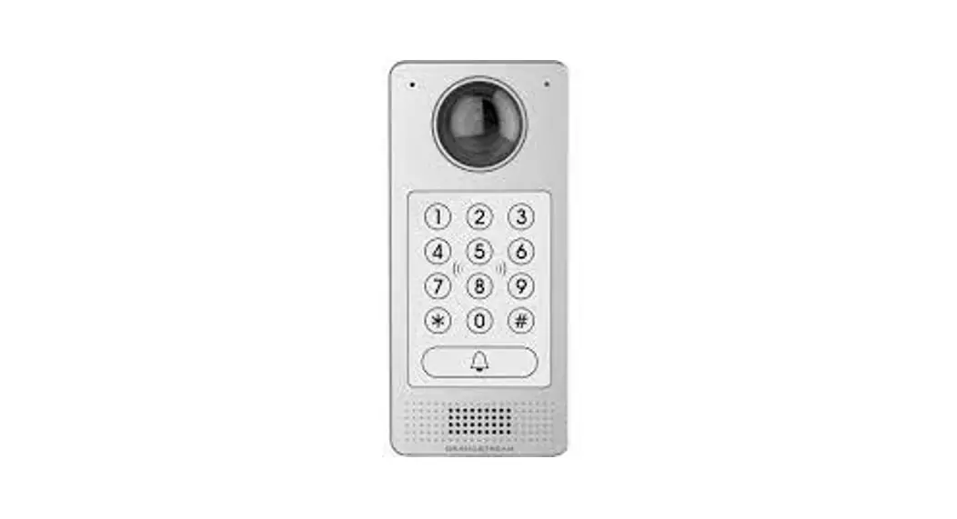
GDS371 0 Hemispheric HD IP Video Door System
Quick Installation Guide
PRECAUTIONS
- Do not attempt to disassemble or modify the device
- Strictly follow the requirement of power source
- Do not expose this device to temperatures out the range of -30 °C to 60 °C for operating and -35°C to 60°C for storage
- Do not expose this device to environments outside of the following humidity range: 10-90% RH (non-condensing)
- Please strictly follow the instruction to install or hire professionals to install properly
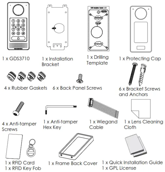
PACKAGE CONTENTS
MOUNTING GDS3710
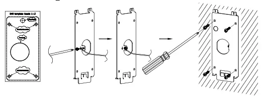
On-Wall (Surface) Mounting
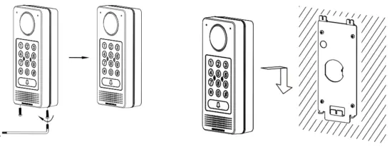
Step 1: Refer to the “drilling template” to drill holes at a targeted place on the wall then mount the installation bracket using the four screws and anchors provided (screwdriver not provided). Connect and tight-en “Ground” wire (If available) to the bracket ground marked with the printed icon ![]() .
.
 Step 2: Pull Ca t5e or Cat6 cable (not provided) through the rubber gasket selecting the correct size and the back cover panel piece, please-fer to “GDS 371 OWIRINGTABLE” at the end of QIG for Pin connections.
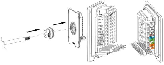 Note: Needle nose plier highly recommended and 2.5mm flat screwdriver required (not provided). Stripping the outer plastic shield of the cable in less than 2 inches is suggested. Do NOT leave bare metal outside the socket by over stripping the inner plastic shield of the wires.
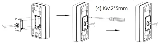
Step 3: Make sure the “Back Cover Frame” Is in place, the wired back cover panel is good. Flush the back cover panel piece with the whole back surface of the device, tighten it using the screws provided.
 Step 4: Take out the two preinstalled anti-tamper screws using the hex key provided. Carefully align the GDS3710 to the metal bracket on the wall, and press and pull the GDS3710 down to the right position.
 Step 5:,Install the two anti-tamper screws back using the hex key provided (do NOT over-tighten the screws). Cover the two screw holes on the bottom of the “Back Cover Frame” piece using the two silicon ,,,,,, plugs provided. Final check and finish the installation.
 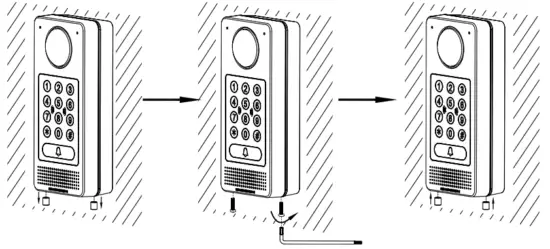 ►In-Wall (Embedded) Mounting
Please refer to the “In-Wall (Embedded) Mounting Kit”, which can be purchased separately from Grandstream.
CONNECTING THE GDS3710
Refer to the illustration below and follow the instructions on the next page.![]() POWER OFF GDS3710 when connecting wires or inserting/removing the back cover panel piece!
POWER OFF GDS3710 when connecting wires or inserting/removing the back cover panel piece!
Option A: RJ45 Ethernet Cable to (Class 3) Power over Ethernet (PoE) Switch.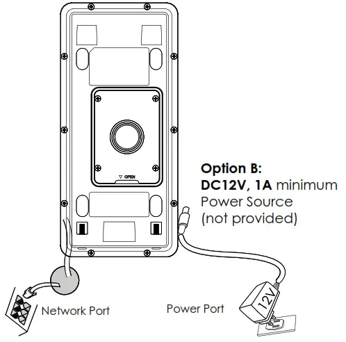 Note: Choose Options A if using PoE switch (Class 3); OR: Option B if using 3rd party power source.
Option A
Plug an RJ45 Ethernet cable into the (Class 3) Power over Ethernet(PoE) switch. Option B Step 1: Select an external DC12V, minimum 1A power source (not provided). Wire correctly the “+,-” cable of the pow-er into the “12V, GND” connector of the GDS3710 socket (refer to the previous mounting page for instruction). Connect the power source.
Step 2: Plug an RJ45 Ethernet cable into a network switch/hub or router.
Note: Please refer to “Step 2” of “MOUNTING GDS3710” and “GDS3710 WIRING TABLE” at the end of QIG for all the wiring and connection illustrations and instructions.
GDS3710 CONFIGURATION
The GDS3710 is by default configured to obtain the IP address from the DHCP server where the unit is located.
In order to know which IP address is assigned to your GDS3710, please use the GS_Search tool as illustrated in following steps.
Note: If no DHCP server is available, the GDS3710 default IP address (after 5 minutes DHCP timeout) is 192.168.1.168.
Step 1: Download and install the GS_Search tool: http://www.grandstream.com/supoort/tools
Step 2: Run the Grandstream GS_Search tool on a computer connected to same network/ DHCP server.
Step 3: Click on Seach the button to start device detection.
Step 4: The detected devices will appear in the output field as below.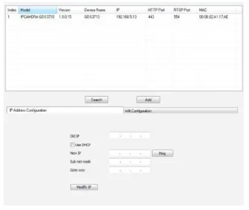
Step 5: Open the web browser and type the displayed IP address of GDS3710 with the leading HTTPS:// to access the web GUI. (For security reasons, the default web access of GDS3710 is using HTTPS and port 443.)
Step 6: Enter your username and password to login. (The default administrator username is “admin” and the default random password can be found at the sticker on the GDS3710).
Note: For security reasons, make sure to change the default admin password from System Settings > User Management.
 Step 7: After login into the WebGL, click the left side menu in the web interface for more detailed and advanced configuration.
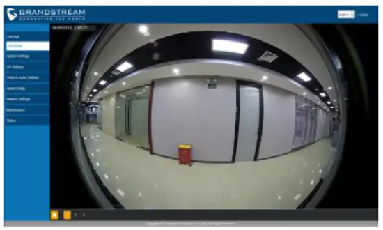
Step 8: To view the video feed, access to LiveView. The browser will indicate that Active-X or Video Plug-in is required. Follow the displayed instruction to download and install it. Click the “Play” button to view the selected video feed.
Below is an example screenshot with the successful Active-X or Plug-in installation.
 Refer to online documents and FAQ for more detailed information: http://www.grandstream.com/our-oroducts
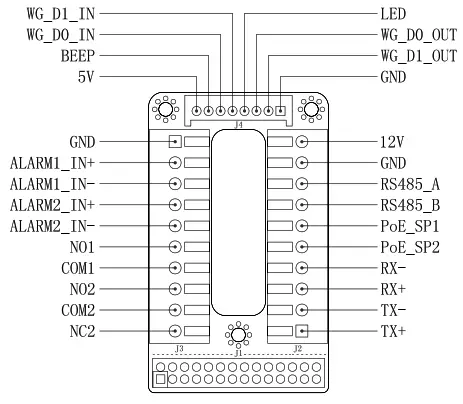
GDS3710 WIRING TALE
| Jack | Pin | Signal | Function |
| .1 2 (Basic) 3.81mm | 1 | TX+ (Orange/White) | Ethernet. PoE 802.3at Class3. 12.95W |
| 2 | TX- (Orange) | ||
| 3 | RX+ (Green/White) | ||
| 4 | RX- (Green) | ||
| 5 | PoE SP2 (Blue + Blue/ While) | ||
| •-• 6 | PoE SPI (Brown + Brown/ While) | ||
| 7 | RS485_B | R5485 | |
| 8 | RS485_A | ||
| 9 | GND | Power Supply | |
| 10 | 12V | ||
| J3 (Avanced) 3.81mm | 1 | GND | Alarm GND |
| 2 | ALARMUN+ | ALARM IN | |
| 3 | ALARM1_11.4- | ||
| 4 | ALARMUN+ | ||
| 5 | ALARM2 – IN- | ||
| 6 | NOl | Alarm Out | |
| 7 | COMI | ||
| 8 | NO2 | Electric Lock | |
| 9 | COM2 | ||
| 10 | NC2 | ||
| J4 (Special) 2.0mm | I | GND (Black) | Wiegand Power GND |
| 2 | WG_Dl_OUT (Orange) | Wiegand Output Signal | |
| 3 | WG_DO_OUT (Brown) | ||
| 4 | LED (Blue) | Wiegand Output LED Signal | |
| 5 | WG_DO_IN (White) | Wiegand Input Signal | |
| 6 | WG_DO_IN (Green) | ||
| 7 | BEEP (Yellow) | Wiegand Output BEEP Signal | |
| 8 | 5V (Red) | Wiegand Power Output |
For more details regarding GDS3710 wiring, please refer to User Manual.
| Electric Lock | GDS3710 Connection | Door | ||||
| Type | Power On | Power Off | NC2 | NO2 | COM2 | Normal Status |
| Fail Safe | Lock | Open | ■ | ■ | Lock | |
| ■ | ■ | Open | ||||
| Fail Secure | Open | Lock | ■ | ■ | Lock | |
| ■ | ■ | _Open | ||||
| NOTE: Please select the correct wiring based on different electric strike/lock and the normal status of door. Electric Magnetic Lock will work at Fail Safe mode ONLY. | ||||||
Note:
- Power PoE SP1, PoE SP2 with DC, the voltage range is 48V-57V, no polarity.
- Power with PoE the cable wiring.
• PoE SP1, brown and brown/white binding
• PoE SP2, blue and blue/white binding - DC Power could be correctly sourced from qualified PoE Injector.
This product is covered by one or more of the U.S. patents (and any foreign patent counterparts thereto) identified at www.cmspatents.com.
Grandstream Networks, Inc.
126 Brookline Ave, 3rd Floor Boston, MA 02215. USA
Tel : +1 (617) 566 – 9300
Fax: +1 (617) 249 – 1987
www.grandstream.com
For Warranty and RMA information, please visit www.grandstream.com


