
ZOELLER FM2931 Apak Outdoor Alarm
ALARM INSTALLATION INSTRUCTIONS
For indoor use only.
All electrical and safety codes must be followed in addition to the National Electrical Code and all applicable local codes.
SPECIFICATIONS
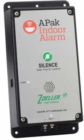
This alarm unit monitors liquid levels in lift pump chambers, sump pumps basins, holding tanks, and other non-potable water applications. It features a green
“power on” light, a red input light, an audible buzzer, and a silence/test button. The APak® plugs into a 120 V, 60 Hz receptacle. Battery backup power is applied by two standard alkaline AA batteries, which are not included and must be purchased separately (see Figure A).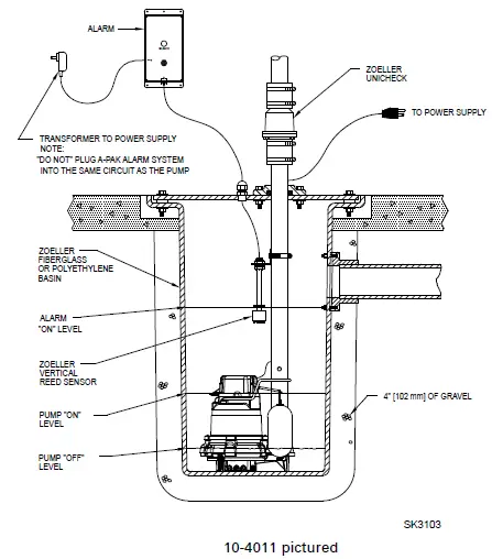
ALARM UNIT INSTALLATION
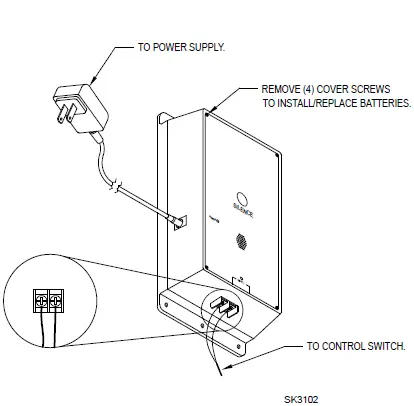
- Before installing the alarm, remove the 4 cover screws to access the battery compartment (see Figure B) and install two standard alkaline AA batteries, not included.
- Mount the alarm unit securely.
- Plug transformer’s barrel connector into the APak®. Secure power cord so it does not interfere with or obstructs any other devices.
- Plug transformer into standard, 120 VAC, 60 Hz receptacle.
NOTE: The APak® Alarm should be connected to a circuit separate from the pump circuit.
Installations using AC power and batteries can skip the following explanation and chart. Some installations may require the APak® alarm to be powered by batteries only or by AC power only. For appropriate alarm behavior in such installations, see the following chart.
| Power choice | Resulting alarm behavior | Do this |
| AC & batteries | Alarms for power outage and low battery. | Insert batteries and connect to power. |
| AC only | Low battery alarm disabled. | Hold button while powering up the alarm for about 5 seconds until a single beep is heard, then release the button. This setting will be remembered by the alarm even after a power outage. If this setting is no longer desired, simply adding batteries will remove this setting. |
| Batteries only | Power outage alarm disabled. | Insert batteries. The alarm will not detect AC power if it is never applied. |
LIMITED WARRANTY
Manufacturer warrants, to the purchaser and subsequent owner during the warranty period, every new product to be free from defects in material and workmanship under normal use and service, when properly used and maintained, for a period of 3 years from the date of purchase by the end-user. Parts that fail within the warranty period, that inspections determine to be defective in material or workmanship, will be repaired, replaced or remanufactured at the Manufacturer’s option, provided, however, that by so doing we will not be obligated to replace an entire assembly, the entire mechanism or the complete unit. No allowance will be made for shipping charges, damages, labor or other charges that may occur due to product failure, repair or replacement. This warranty does not apply to and there shall be no warranty for any material or product that has been disassembled without prior approval of Manufacturer, subjected to misuse, misapplication, neglect, alteration, accident or uncontrollable act of nature; that has not been installed, operated or maintained in accordance with Manufacturer’s installation instructions; that has been exposed to outside substances including but not limited to the following: sand, gravel, cement, mud, tar, hydrocarbons, hydrocarbon derivatives (oil, gasoline, solvents, etc.), or other abrasive or corrosive substances, wash towels or feminine sanitary products, etc. in all pumping applications. The warranty set out in the paragraph above is in lieu of all other warranties expressed or implied, and we do not authorize any representative or other person to assume for us any other liability in connection with our products. Contact Manufacturer at, 3649 Cane Run Road, Louisville, Kentucky 40211, Attention: Customer Support Department to obtain any needed repair or replacement of part(s) or additional information pertaining to our warranty. MANUFACTURER EXPRESSLY DISCLAIMS LIABILITY FOR SPECIAL, CONSEQUENTIAL, OR INCIDENTAL DAMAGES OR BREACH OF EXPRESSED OR IMPLIED WARRANTY; AND ANY IMPLIED WARRANTY OF FITNESS FOR A PARTICULAR PURPOSE AND OF MERCHANTABILITY SHALL BE LIMITED TO THE DURATION OF THE EXPRESSED WARRANTY. Some states do not allow limitations on the duration of an implied warranty, so the above limitation may not apply to you. Some states do not allow the exclusion or limitation of incidental or consequential damages, so the above limitation or exclusion may not apply to you. This warranty gives you specific legal rights and you may also have other rights which vary from state to state.
CONTROL SWITCH INSTALLATION
Warning: DO NOT install a sensor in direct line of incoming liquid.
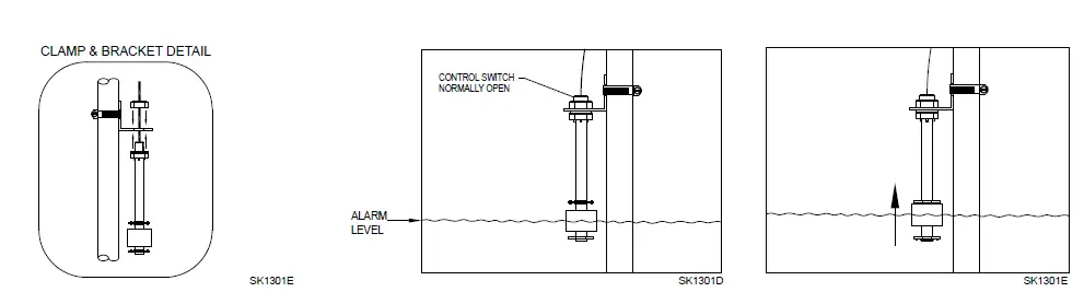
- Fasten sensor to right-angle mounting bracket by an unthreading plastic nut. Re-tighten plastic nut after inserting sensor stem in bracket (see Figure C).
- Locate sensor at desired activation level and secure mounting bracket to the discharge pipe as shown (see Figures C, D, and E) using supplied hose clamp. NOTE: DO NOT install cord under hose clamp.
- Secure sensor cord to discharge pipe. Be sure not to leave any loose cord that could rub against and obstruct other devices in basin assembly.
NOTE: Create a cable strain relief when securing the control switch cord by fastening a 2” loop of the cord to the pipe with a cable tie or tape. Be sure sensor float moves up and down without interference.
NOTE: Alarm system 10-4012 is recommended for sewage applications. If a 10-4011 is used in a sewage application, the float should be inspected and cleaned as necessary, after any high water incident.
MECHANICAL FLOAT SWITCH
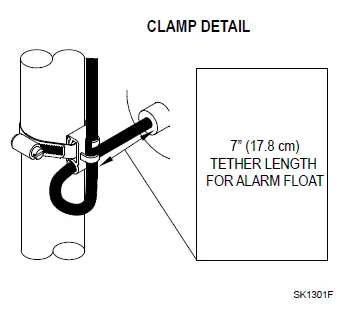
- Place cord into the clamp and secure to discharge pipe as shown in clamp detail (see Figure F).

NOTE: Do not install the cord under the hose clamp. - Tighten the hose clamp with a screwdriver. NOTE: Do not overtighten; overtightening may cause damage to the plastic clamp.
- Make sure the float cable is not allowed to touch the excess hose clamp band during operation.
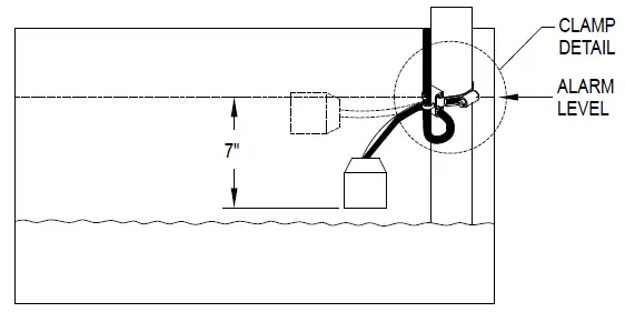
- The float switch must be suspended seven inches below desired activation level (see Figure G).

LIFT PUMP
Suspend control switch above pump turn-on level. If a pump failure causes a high-level condition, the APak® Alarm System will activate (see Figure A).
HOLDING TANK
Suspend control switch into tank 7” (17.8 cm) below desired alarm level. APak® Alarm System will activate if float ascends to alarm level (see Figure G).
CONTROL/MECHANICAL SWITCH WIRING
Connect the two conductors from the control or mechanical switch to the terminations on the bottom of the alarm unit (see Figure B). The control switch operates on low voltage to reduce shock hazards.
OPERATION AND TEST
Check and test your installation by lifting the float manually (see Figure E or G). The alarm unit will indicate an alarm condition by beeping and lighting a red LED above “Input 1”. The alarm may be silenced for 24 hours by briefly pressing Silence button. Once silenced, the LED changes to a flashing state and the audible horn will not sound. Once the high-water condition is remedied, the alarm should be reset by holding the Silence button for 3 seconds. Zoeller Company cannot be responsible for damages caused by faulty or negligent installation of this device. We respectfully suggest you engage the services of a qualified licensed electrician or service person. Hold the Silence button for more than 3 seconds to Test once per week to verify proper operation.
| AC and DC Mode | AC Only Mode | DC Only Mode | ||
|
LED and Alarm Behaviors | Power LED | Power LED is on when AC and DC power are present. | Power LED is on when AC power is present. | Power LED off when only batteries have been inserted, but will blink when button pressed. |
| Input 1 Alarm | Input LED on solid. Alarm triple beeps continuously. | Input LED on solid. Alarm triple beeps continuously. | Input LED blinks and alarm double beep every 5 seconds. | |
| Low Battery Alarm | Power LED blinks. Alarm triple beeps every 5 seconds. | N/A | Power LED blinks and alarm beeps every 10 seconds. | |
| Power Out Alarm | All LEDs go out to conserve bat- tery power. Power LED blinks and alarm double beeps every 30 seconds. | N/A | N/A | |
|
Silence Button | Press/Release | Silences Alarms. LED that is in alarm stays on (or blinks) until APak® is Reset. | Silences Alarms. LED that is in alarm stays on (or blinks) until APak® is Reset. | Silences alarm. LED still blinks every 5 seconds until alarm is Reset. In standby mode, a short beep will occur to indicate APak® is ready. |
| Hold 3 Seconds | Resets any active alarms and returns APak® to standby mode. | Resets any active alarms and returns APak® to standby mode. | Resets any active alarms and returns APak® to standby mode. | |
| Hold 4 Seconds | Initiates a LED and Alarm Test. Will flash and double beep 3 times. | Initiates a LED and Alarm Test. Will flash and double beep 3 times. | Initiates a LED and Alarm Test. Will flash and double beep 3 times. | |
| Hold 12 Seconds | Complete reset of APak® to factory settings. | Complete reset of APak® to factory settings. | Complete reset of APak® to factory settings. | |
| Battery Life | Battery Life | 1-2 years with normal use. | N/A | Approximately 1 year with normal use. |
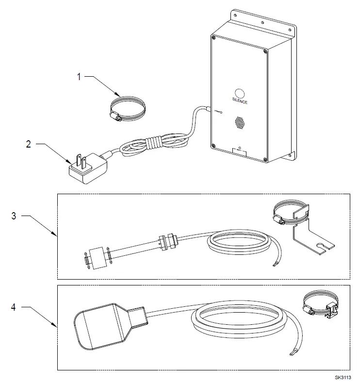
| Models | 10-4011-A | 10-4012-A | ||
| Item | Description | Qty | 3/16 thru Current | 3/16 thru Current |
| 1 | Clamp, #36 Worm-SS | 1 | 001766 | 001766 |
| 2 | Supply, Power (Service Part) | 1 | 154018 | 154018 |
| 3 | Switch, Vertical Reed (Service Part) | 1 | 154033 | N/A |
| 4 | Switch, Mechanical Float | 1 | N/A | 10-2060 |
INSTRUCTIONS
MAIL TO: P.O. BOX 16347 • Louisville, KY 40256-0347 SHIP TO: 3649 Cane Run Road • Louisville, KY 40211-1961 (502) 778-2731 • 1 (800) 928-PUMP • FAX (502) 774-3624 Visit our web site: zoellerpumps.com


