
MYPV AC ELWA 2 Hot Water Heater Instruction Manual
Intended use
The AC ELWA 2 is intended for stationary installation in hotwater boilers or buffer storage tanks. The device takes linearly regulated power from the house mains according to external control signals.
Any application other than those described above may cause damage. Furthermare, this maylead to hazards such as a short circui, fire, electric shock, etc. The safety instructions and the information on handiing in this manual and in the operation instructions shall be followed!
The producs complies with the statutory, national and European requirements. The names of the company &nd products are trademarks of myPV GmbH. All rights reserved
![]() You will find a comprehensive description of the unit’s functions and potential settings using the display or via web interface in the online Operating instructions [reference on the title page).
You will find a comprehensive description of the unit’s functions and potential settings using the display or via web interface in the online Operating instructions [reference on the title page).
Scope of supply
- Electric water heater AC ELWA 2 (three-part)
- Beectronic unit (incl. dummy plug for AUX relay connector)
- Heating rod incl. plug 6-pole, O-ring seal and temperature sensor T1 (in heating element)
- Connecting frame and fixing screw (Torx TX2O 4x25mm)
- Accessory box
- Antirotation screw (Torx TX20 4.8¢13mm)
- Plug 3pole (L PE N for power supply incl. strin relief (2 parte) and fixing screw (Torx TX10 3x8mm)
- Plug 3-pols (NO COM NC) for AUX relay incl. strein relief (2 parte) and fixing screw (Torx TX10
- 3x8mm) External temperature sensor T2 (cable length 57)
- 8pole plug WiFi antenna 120 Ohm resistor for RS485 communication
- Operator stylus for the display o Holder for operator stylus
- Assembly instructions
- Quickstart guide
- Give Avay
Safety instructions
The electrical connection, commissioning and service wark may only be performed by an authorized specialist.
When installing and connecting the relevant standards must be observed.
The electronic unit may only be connected to the enclosed heating rod from my-PV. Other heating rods (except those expresaly approved by my PV are not permitted!
A permanent earthing of the hot water tank is mandatory.
Never switch the unit an when the heating element is nat surrounded and caoled by water.
The housing must not: get damp or wet, it is only suitable for dry indoor areas. There s a risk of fatal electric shock!
Installation in rooms with a high level of humidity must comply with relevant. regulations!
Do not install device in ammonia-contaminated environments.
Do ot install in dusty environment:
The ventilation holes of the housing must not be covered
The housing of the device may heat up during operation.
Avoid exposure to intense het, cold or direct sunlight during storage and operation. See technical data
The safety temperature limiter (STL) responds at approx. 100°C and switches off the device. Caution when used in unpressurized storage tanks!
Do not reset the safety temperature limiter (STL) until the cause of the trip has been eliminated.
Before carrying out any work, the device must be disconnected from the power supply.
![]() The plug of the power supply (L PE N) mus never be disconnected under voltage!
The plug of the power supply (L PE N) mus never be disconnected under voltage!
![]() fosay relay is a potentialfree switching contact for safety extraow voltage. Do not connect: mains voltage under any circumstances. There is a danger to life!
fosay relay is a potentialfree switching contact for safety extraow voltage. Do not connect: mains voltage under any circumstances. There is a danger to life!
The maximum operating pressure is 10 bar.
In commercial institutions, the accident prevention regulations of the professional associations must be observed for electrical systems and equipment.
This unit can be used by children ages 8 and persons with reduced physical, sensory or mental capabilies or lack of experience and knowledge if they have been given supervision or instruction concerning the safe use of the equipment and understand the resulting risks. Children should not play with the appliance. Cleaning and user maintenance shall not: be undertaken by children without supervision.
Liability and warranty exclusion
Alibility and warranty exclusion applies to
- Damage to property or personal injury caused by improper handling or non-observance of the safety instruction and the service assembly and opportunity instruction.
- Conequentiel demagee. Unauthorized remodeling, disassembly or other interventions in the device, madification of the product.
- Damage caused by calcium deposits on heating element.
- Damage caused by corrosion at heating element.
Connections

- Electronic unic 1
- Mains connection for power supply from the electric cabinet
- AUX relay: 16A switching output for external heating element (max. 3 kW), Closed with dummy plug on delivery.
- SELV relay: potentiatfree switching contact for safety extralow voltage AN
- comnect mains voltage under any circumstances. There is a danger to lifet
- External temperature sensor T2 (Polarity does not matter] PWM In/O1t, Ground/ Earth
- Modbus RTU connection (RS485] LAN connection (RJ45) for network cable
- Connection for Wii antenna
- Fixing screw (Torx TX20 4x25mm) for fixing the electronics unit to the
- connecting frame 1 Connecting frame between electronic unit and heating rod
System overview (on-grid systems)
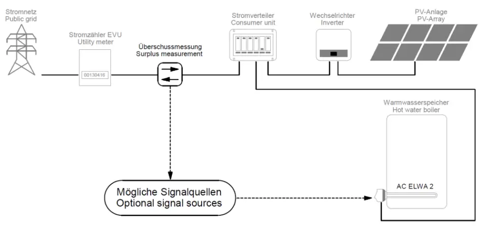
Optional signal sources
my-PV WiFi Meter Instructions can be found here
Compatible manufacturers Instructions can be found here
Other signal source
For control by freely programmable energy management or smart home systems, a description of the open protocols Modbus TGP and http is availsble in a separate document. Thz connection to the signal source is made via LAN or WiFi. The description will be provided on request. Please contact my-PV for this purpose [email protected]
Via RS485, the AC ELWA 2 can only be used as @ Modbus RTU master. Freely programmable control is not possible with this,
Higher-level controllers can also specify the power output via @ PWM signal. The corresponding signal input is located on the B-pin connector to which the T2 temperature sensor is also connected
In oftgrid systems, the power can also be specified via the AC frequency. Addtional cabling for communication is not required in this case.
Communication Interfaces
LAN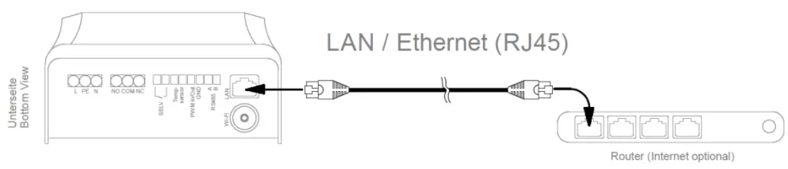
WiFi
For a more stable communication with the signal source, my-PV recommends a LAN connection over a WiFi connection!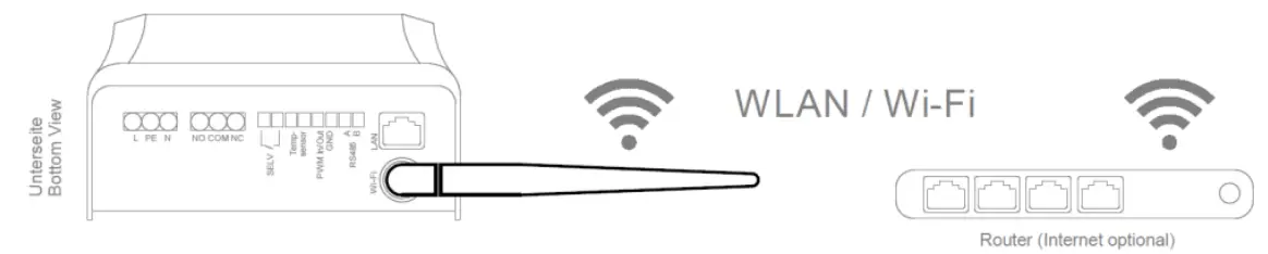
 TIP: To amplify the signal use commercially available Wii repeaters.
RS485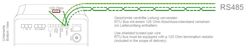
PWM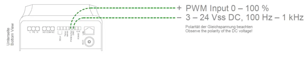
Assembly
A brief video (German with subtitles) to explain assembly will also be found nere: https://youtu.be/ET7DRIPHDE 
Assembly of the heating rod
The hot water storage tank must be drained properly before instaling the heating rod.
The installation position of the unit (heating rod horizontal, electrical connections at the bottom) must be observed.
A socket of suitable thread size (G 1Y) must be available or mounting is done with locknut, which is not included in the scope of delivery.
The unheated zone of the heating rod is 140 mm from the sealing surface. Make sure that the length of the screwin slesve is shorter.
The pre-assembled G-ring seal has to be used. t must not be treated with lubricants. Make sure that the O- ring is properly placed in its groove.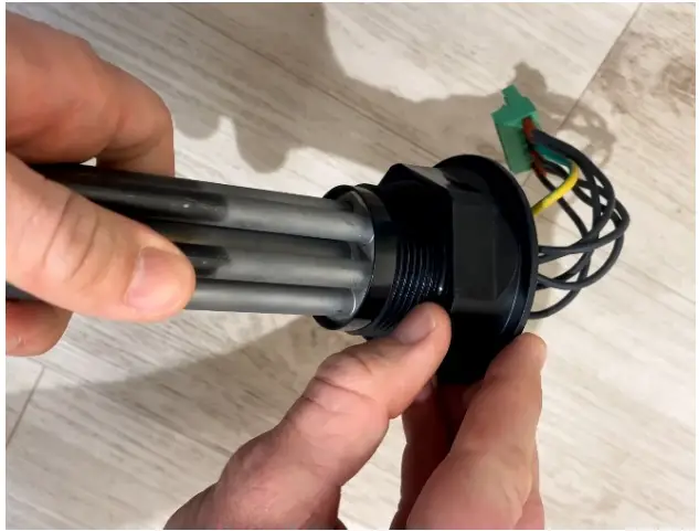
If the sealing with the Q-ring is not possible, other sealants may be used on tre thread.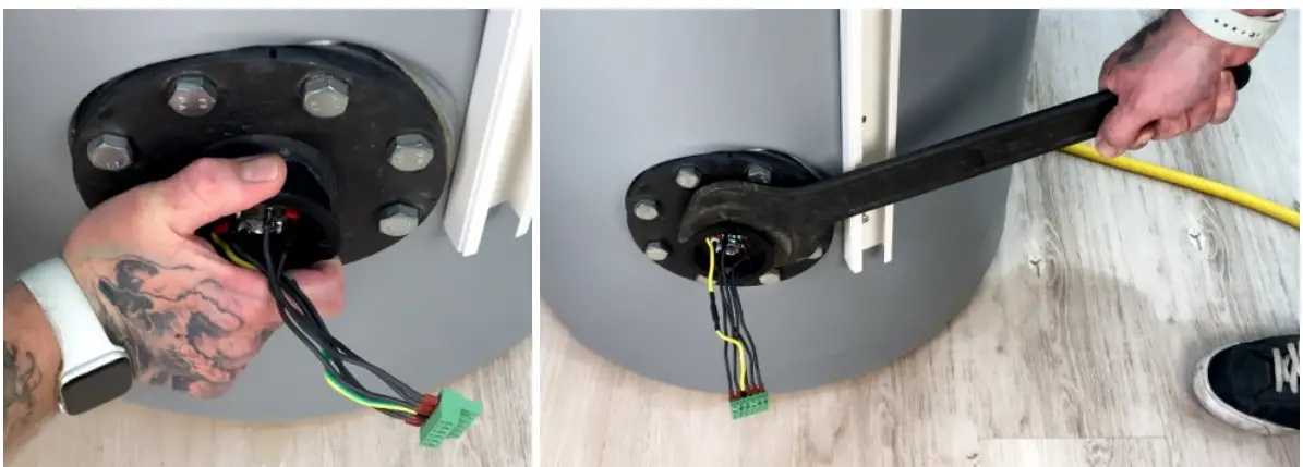
Do not apply force when screwing in the heating rod until the seal is slightly pressed. Then tighten the heating rod with a 60mm spanner. When using a pipe wrench, include a cloth to protect the hexagon!
The tightening torque must not exceed 50 Nm
![]() TIP: This corresponds to a weight of 5 kg with a lever length of one meter, or & weight of
TIP: This corresponds to a weight of 5 kg with a lever length of one meter, or & weight of
10 kg with a lever length of half a moter.
If an adapter flange is used on the tank, we recommend a fiange plate made of stainless steel or at least of &n enamelled material. Otherwise corrosion could occur on the heating elements, but this is excluded from the warranty.
When refilling the water tank ensure that the heating elements are completely surrounded by water. Subsequently, the tank must be checked for leakage:
Putting on the electronic unit
First the anti-rotation screw (Torx TX20 4.8x13mm) must be screwed on. There are two SCrewsin points to choose from. Choose the position that allows the connecting frame to be aligned vertically afterwards (fising screw for electronic unit &t the bottom).
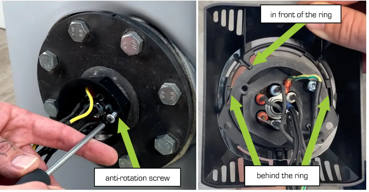
Hook in the black connecting frame. To do this, hold the frame vertically (fxing screw for electronic unit at the bottom) and push it onto the mounting ring of the heating rod from top to bottom until it snaps into place.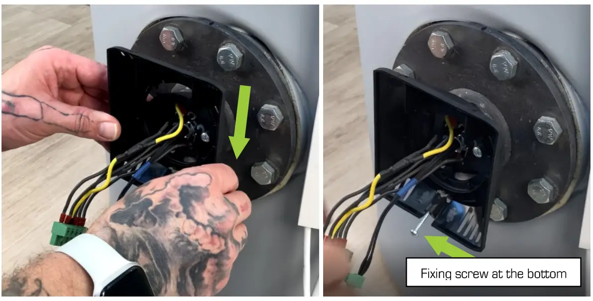
Establish electrical connections between the heating rod and the electronics unit. Start with the 3-pin temperature sensor T1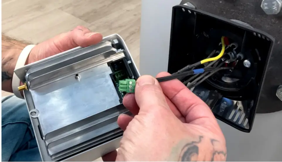
Then plug in the B-pin heating rod connection until it snaps into place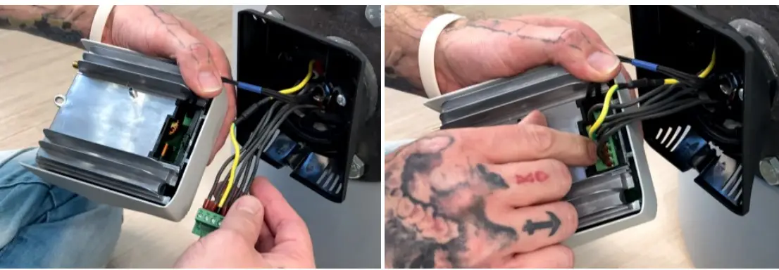
Arrange the wirehang the electronic the from bottom top,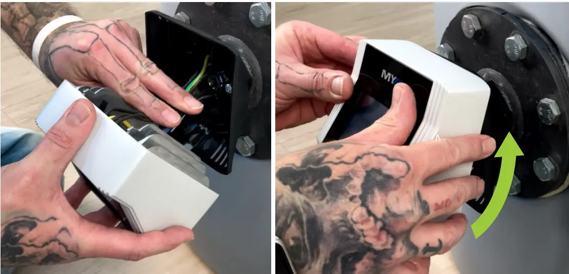
Screw the electronics unit to the connection frame using the fixing screw (Torx TX20 4x25mm).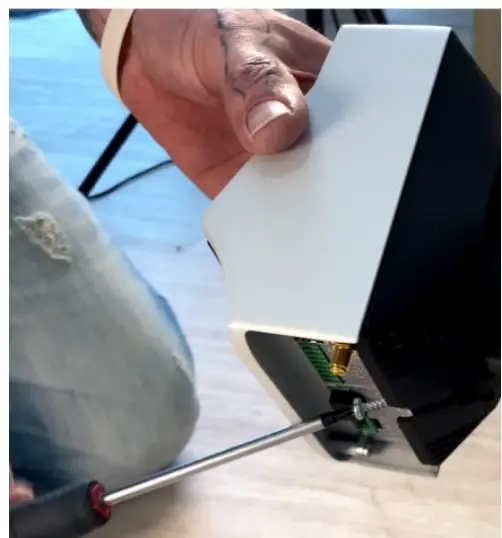
![]() TIP: For easier access, the electronic unit can be turned to the side until it hits the antirotation screw. Don’t use violence!
TIP: For easier access, the electronic unit can be turned to the side until it hits the antirotation screw. Don’t use violence!
Electrical connection
The AC ELWA 2 must be connected to a nominal voltage of 230 VAC, 4565 Hz.
The conductor cross-sections at the mains connection must be at least 2.5 mm?.
The mains connection fuse for the AC ELWA 2 must not exceed 1BA (tripping characteristic B,
No other loads may be connected to the circuit, otherwise the maximum power of the AG ELWA 2 must bs
throttled (see online operating instructions ![]() Settings)!
Settings)!
![]() The PE concuctor of the socket must be connected!
The PE concuctor of the socket must be connected!
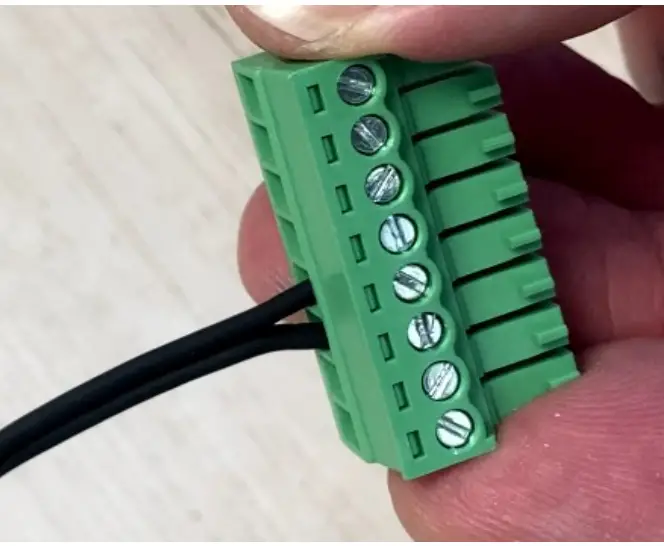
Slide the black plastic nut of the strain relief onto the onsite mains cable (note the direction). Strip the wires and connect them to the screw terminels (torque 0.4 Nm) sccording to the lsbeling on the 3-pin plug (L PE N).
Stripping: outer cable 30mm, wires 7mm.
With fine-stranded wires, we recommend the use of ferrules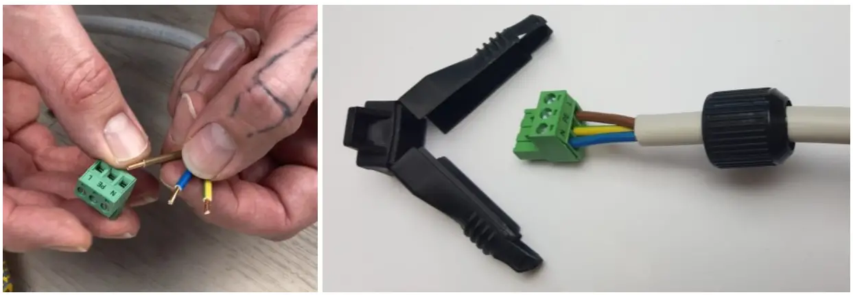
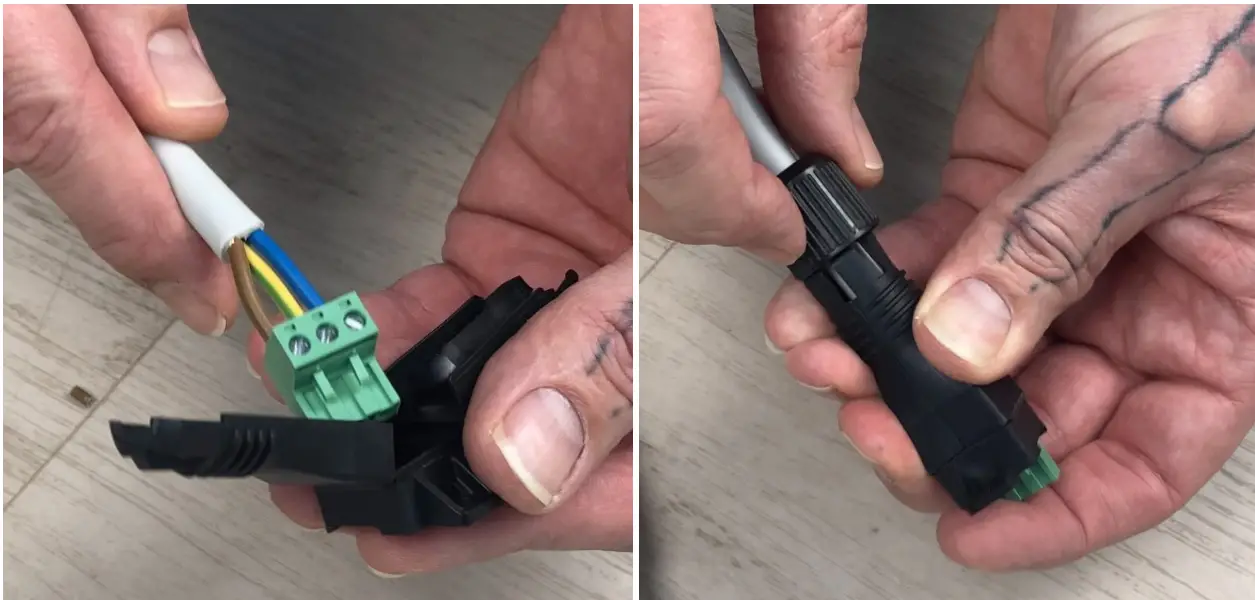
Put the strain over the plug and fix it with the black plastic nut.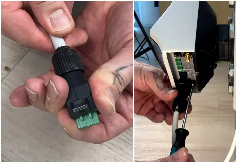
Check tightness. Then mount the cable with the strain relief by using the fixing screw (Torx TX10 3x8mm) on the mains supply connection (L PE NJ of the electronics unit;
![]() A protective earthing conductor test must be carried out between the bare aluminum surface on the underside in the area of the connections and PE! For example according to DIN ENS0899
A protective earthing conductor test must be carried out between the bare aluminum surface on the underside in the area of the connections and PE! For example according to DIN ENS0899
![]() Caution when electrically conductor test must be carried out between the bare several devices Al devices should be connected to appropriate AC circuits. Note that each AC ELWA 2 takes up to 3.5 kW power. It makes sense to diide this between the phases on the grid,
Caution when electrically conductor test must be carried out between the bare several devices Al devices should be connected to appropriate AC circuits. Note that each AC ELWA 2 takes up to 3.5 kW power. It makes sense to diide this between the phases on the grid,
Connection of temperature sensor T2 to the 8-pin connector
Connect temperature sensor T2 to the 8-pin plug (polarity does not mateer). Ensure that terminal points 3 and 4 are correctly assigned!
The further wiring
Depending on the type of communication with the signal source and the operating mode, further connection can be found in the respective wiring diagrams
Application example: The B-pin plug with temperature sensor T2 and & network cable are connected. Then the cables are arranged and the device is aligned vertically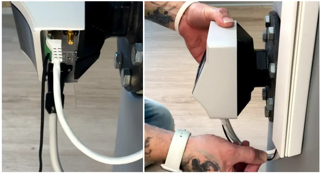
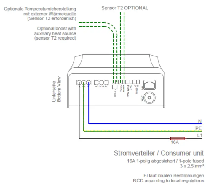
Wiring diagram Mode M1: Hotwater 3’5 kW
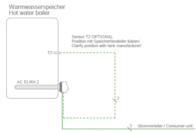
![]() In any case, the temperature sensor T2 (optional) must be attached to the storage tank above the heatng rod in order to deliver a usable measurement result!
In any case, the temperature sensor T2 (optional) must be attached to the storage tank above the heatng rod in order to deliver a usable measurement result!
![]() Do not immerse the temperature sensor T2 directly in water. Use immersion sleeve!
Do not immerse the temperature sensor T2 directly in water. Use immersion sleeve!
Terminal assignment
Wiring diagram Mode M3: Hotwater 3,5 + 3 kW
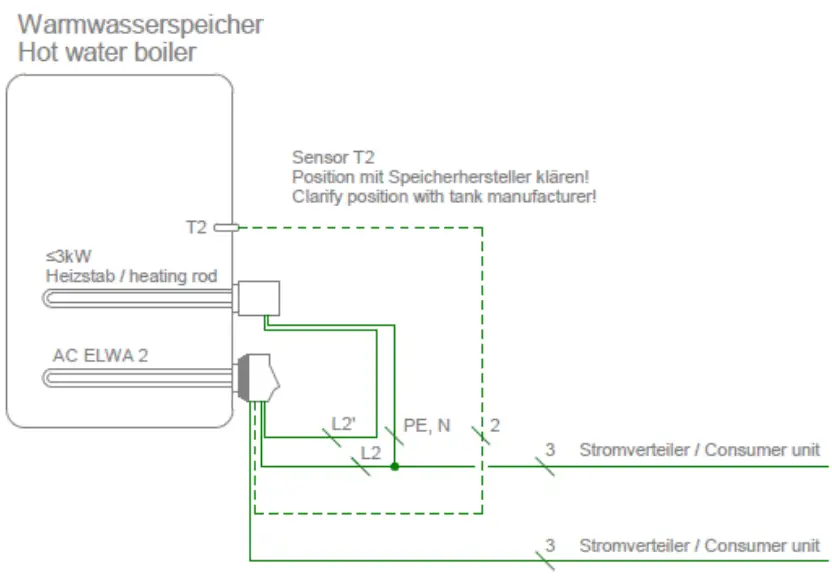
![]() The temperature sensor T2 is always required in this operating mode and must be attached to the
The temperature sensor T2 is always required in this operating mode and must be attached to the
storage tank above the upper heating rod in order to deliver a usable measurement result!
![]() Do not. immerse the temperatire sensar T2 dinectly in water. |se immersion sleevel
Do not. immerse the temperatire sensar T2 dinectly in water. |se immersion sleevel
![]() the output of the external heating element must not be greater than 3 KW. The heating element must be installed with & separate fuse!
the output of the external heating element must not be greater than 3 KW. The heating element must be installed with & separate fuse!
![]() party control types may not be able to command the power up to 6.5 KW!
party control types may not be able to command the power up to 6.5 KW!
Terminal assignment
For correct function, the COM port of the AUX relay must be connected to phese!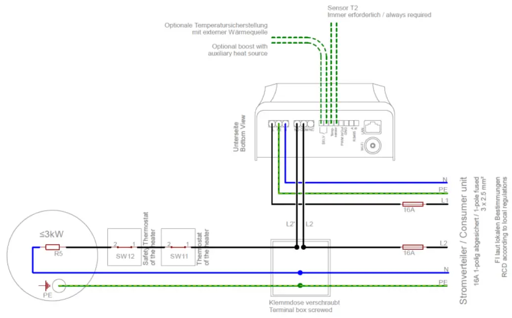
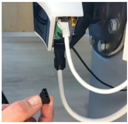
Remove the dummy plug from the AUX relay connector (NO COM NC).
Push the black plastic nut of the strain relief over an on-site two-pole cable (note the direction).
Strip the two wires and connect them to the COM and NO terminal points of the 3pin connector for the
AUX relay (torque 0.4 Nm).
Make the connection to the upper heating element via a screwed terminal box (on-site, see terminal assignment).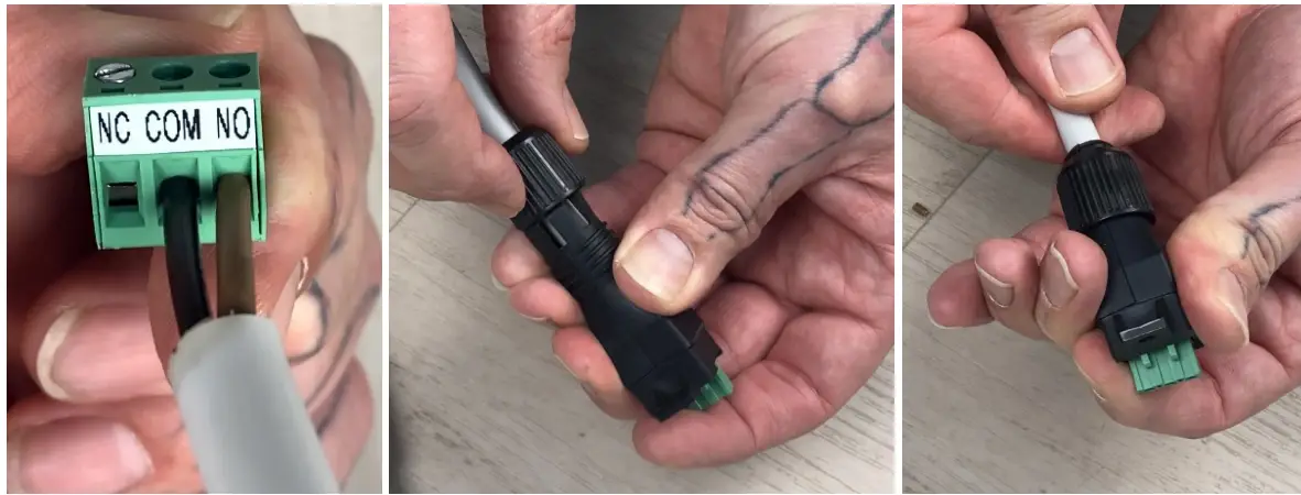
Put the strein relief over the plug and fix it with the black plastic nut. Check tightness.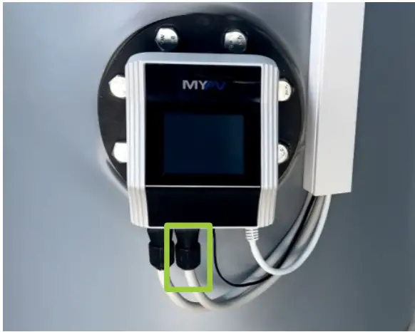
Then connect the strain relief with the fixing screw (Torx TX10 3x8mm] ta the AUX relay (NO COM NC] of the electronics unit.
Maintenance
![]() Du ol alleript W oper the electronic uril. 1L dues nol conlain any perts Uisl may be repaired by Ue user.
Du ol alleript W oper the electronic uril. 1L dues nol conlain any perts Uisl may be repaired by Ue user.
![]() Never aplash water on or in the unit!
Never aplash water on or in the unit!
When it is unplugged, the surface of the unit can be cleaned either with a damp cloth, using mild glass cleaner or cleaning tissue for glasses.
In & polluted environment;, the air inlets and outlets should be checked regularly for cleanliness. If necessary, the unit can be cleaned through the air slots with a vacuum cleaner.
![]() The it canno work et mesimum efficiency if the air supply is inadequate!
The it canno work et mesimum efficiency if the air supply is inadequate!
Calciferous water can cause calcification of the heating rod. When in contact with drinking water, we therefore recommend setting & target temperature of max 60°C! We recommend an annual review. To do this, dismantle the heating rod from the storage tank and remove limescale. Do not scratch the surface of the heating element (formation of corrosion).
Operation displays
The unit has a touch screen to show operating conditions and for ease of operation
![]() Never touch the screen with pointed objects or those having sharp edges!
Never touch the screen with pointed objects or those having sharp edges!
For hest. use the supplied nperator stylus. The holder for the styius can be stuck close t0 the unit with the adhesive patch,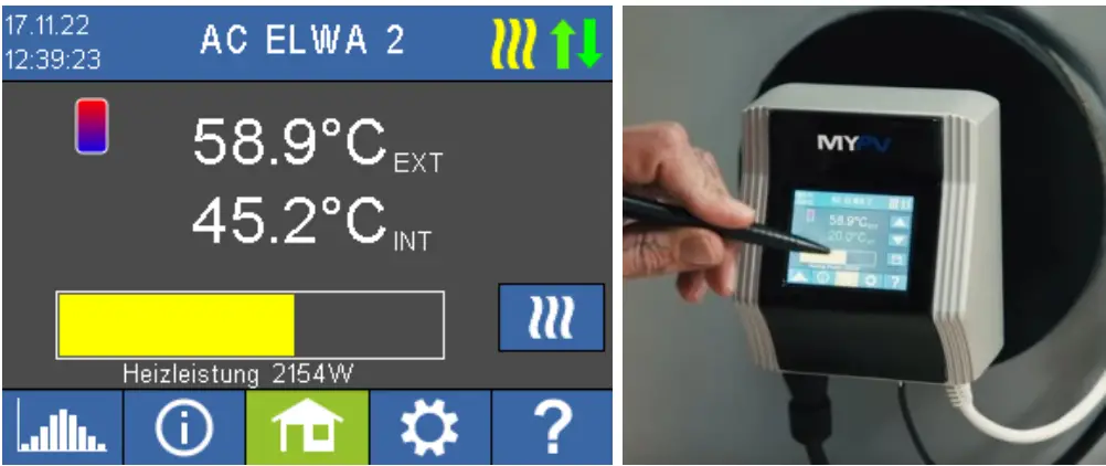
![]() You will find a comprehensive deseription of the unit’s functions and potential settings using the display or via web interface in the online Operating instructions (reference on the tile page).
You will find a comprehensive deseription of the unit’s functions and potential settings using the display or via web interface in the online Operating instructions (reference on the tile page).
Troubleshooting
The device does not contain any parts that may be repaired by the user. In the event of a fault, please contact your specialist dealer or supportemypv.com.
Disposal
Packaging material must be either stored or disposed of as appropriate. Dispose of the product at the end of ts service life according to the statutory regulations,
EU declaration of conformity
You can find them et any time on www.my-pv.com
Technical specifications
| Heating power | 0-3,500 W + relay output 16 A |
| Fuse protection | 13 A or 16 A |
| Mains connection | 3-pole terminal, 2.5 mm2 230 V, 45 – 65 Hz |
| Self-consumption | < 1,5 W |
| Efficiency | > 99,3 % at nominal power |
| Cos Phi | 0,999 at nominal power |
| Certification | CE, TOR D1, TAEV, TAB |
| Mains-side THDi | At 50 %power < 3 %; at 100 % power < 3 % |
| Display | Color Graphic, Touch Screen 2,83″ |
| Communication | Ethernet RJ45,Wifi, R5485, PWM-in 3 – 24V 100 Hz – 1 kHz, galvanically isolated relay contact |
| External temperature sensor | 5 m |
| Protection class | IP 21 |
| Dimensions [W x H x D] | 580 x 133 x 117 mm [incl. heating rod] |
| Heating rod length | 460 mm (from the sealing] |
| Heat-free zone | 140 mm |
| Weight | 2 kg |
| Heating rod thread dimension | 1 1/2 inch |
| Tightening torque | 50 Nm |
| Operating temperature range | Ambient temperature at the casing 0 °C to 40 °C |
| Permissible humidity | 0 – 99 % [not condensing] |
| Storage temperature | -20 °C to 70 °C |
| Max. operating pressure | 10 bar |
| Mounting position | horizontal |
| Warranty | 2 years |
| Maximum number of units in IP network | Network dependent |
| Compatible battery storage / smart home controllers | See www.my-pv.com |
Subject to changes and printing errors.
my-PV GmbH
Betriebsstraf3e 12, 4523 Neuzeug
www.my-pv.com


