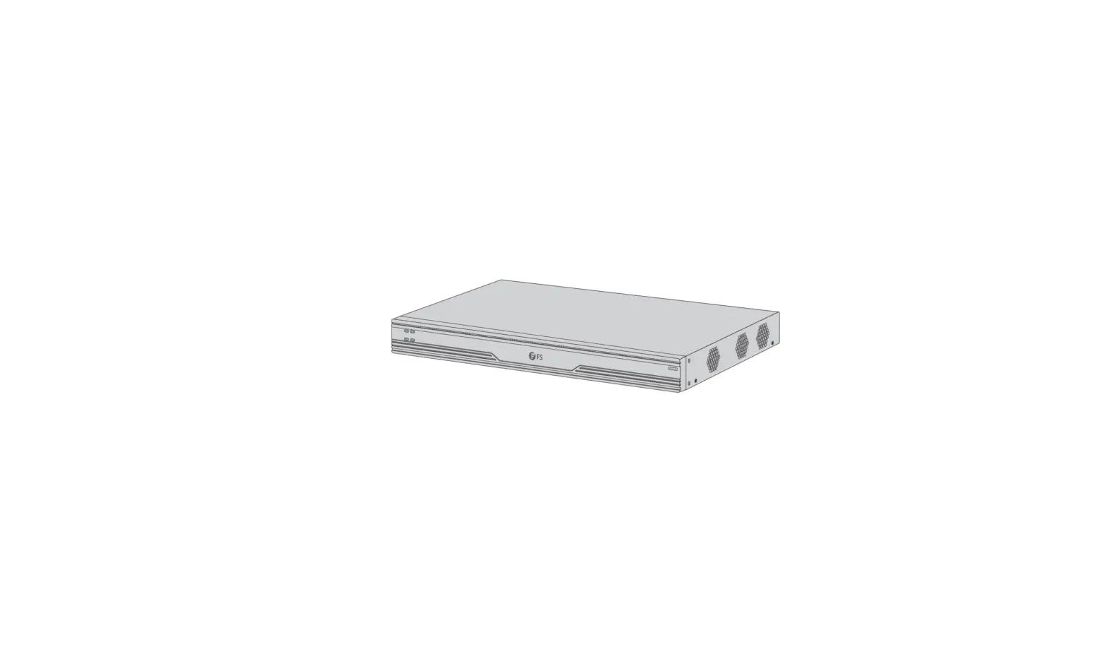
FS VMS-201C Video Management Server
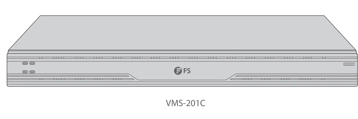
VMS-201C
Introduction
Thank you for choosing Video Management Server. This guide is designed to familiarize you with the structure of the Server and describes how to deploy the Server in your network.
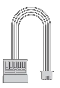
Accessories
- External power cord x1

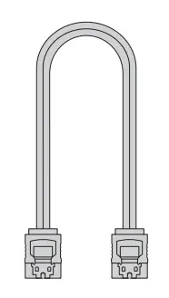
- High-speed signal cable x1

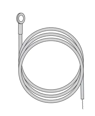
- Common electronic cable x1

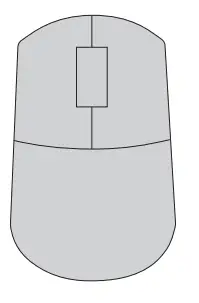
- Mouse x1

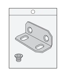
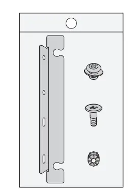
- Mounting bracket component x1

- Sheet metal component x1

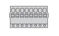
- Cable connection terminal x6

Hardware Overview
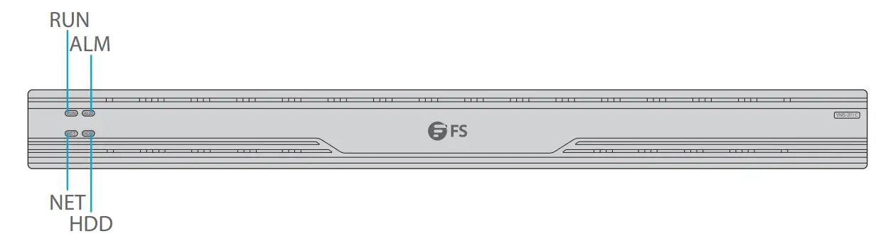
Front panel LEDs
| LEDs | State | Description |
| RUN | Steady on | Normal. |
| Blinking | Starting up. | |
| ALM | Steady on | Device alarm. |
| NET | Steady on | Connected to network. |
| HDD | Off | No hard disk, or disk is not connected to power. |
| Steady on | No data reading or writing. | |
| Blinking | Reading or writing data. |
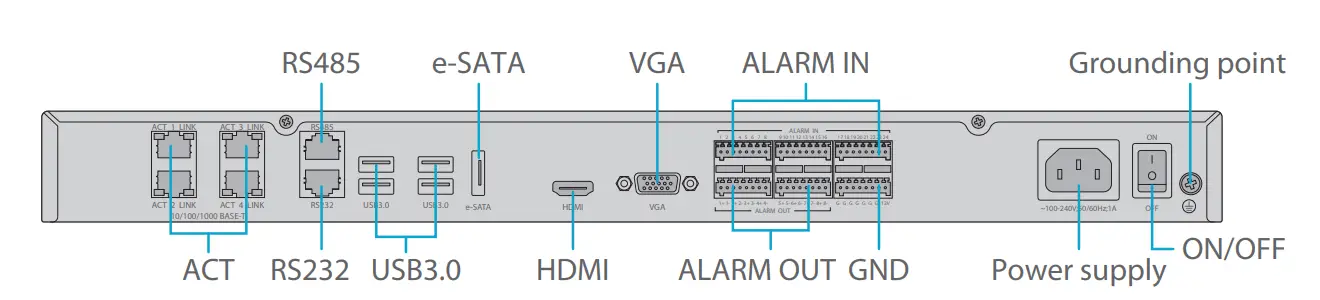
Back Panel Ports
| Ports | Description |
| ACT | Network interface, used to connect an Ethernet network switch |
| RS485 | Serial port, used to interoperate with the connected device |
| RS232 | Serial interface, used to debug and maintain the device |
| USB3.0 | Used to connect USB devices such as USB flash drive, USB mouse and USB keyboard |
| e-SATA | Used to connect an e-SATA disk |
| HDMI | HDMI output, used to connect HDMI interface on a display device |
| VGA | VGA output, used to connect the VGA interface on a display device |
| ALARM IN | 24-channel alarm input, used to connect alarm devices such as a magnetic door sensor |
| ALARM OUT | 8-channel alarm output, used to connect alarm devices such as an alarm siren or alarm lamp |
| GND | The 12V (rightmost pin) is the power output |
| Power supply | 220AC power input |
| ON/OFF | Power switch |
| Grounding point | Grounding terminal |
Installation
Please follow the steps if disk installation is necessary. The illustrations are for reference only.
![]() NOTE: Please use the SATA disks recommended by the manufacturer. Disconnect power before installation.
NOTE: Please use the SATA disks recommended by the manufacturer. Disconnect power before installation.
Preparation
- Prepare a PH2 Philips screwdriver.
- Prepare an antistatic wrist strap or antistatic gloves during the installation.
Disk Installation
- Loosen the screws on the rear panel and side panel and remove the upper cover.
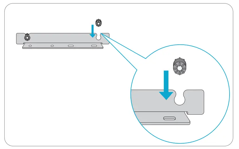
- Attach the 4 gaskets on the brackets.

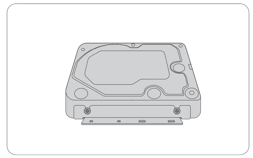
- Secure the disk on the brackets by using fixing screws.
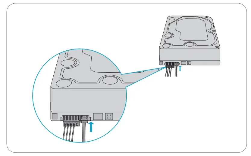
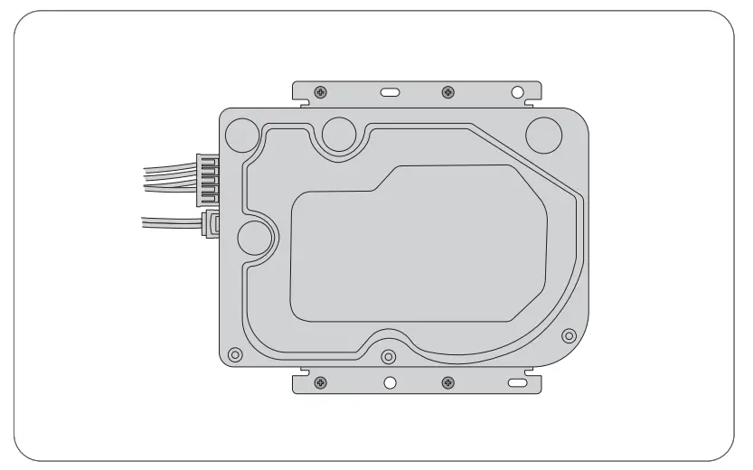
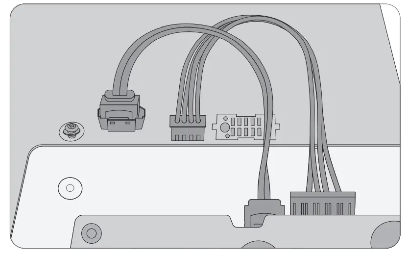
- Connect one end of the data cable and power cable to the hard disk.
- Place the disk in the chassis and secure it with 4 fixing screws (M3*5).
- Connect the other end of the data cable and power cable to the motherboard.
Rack Mounting
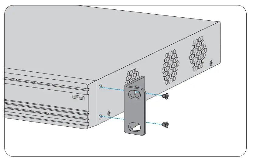
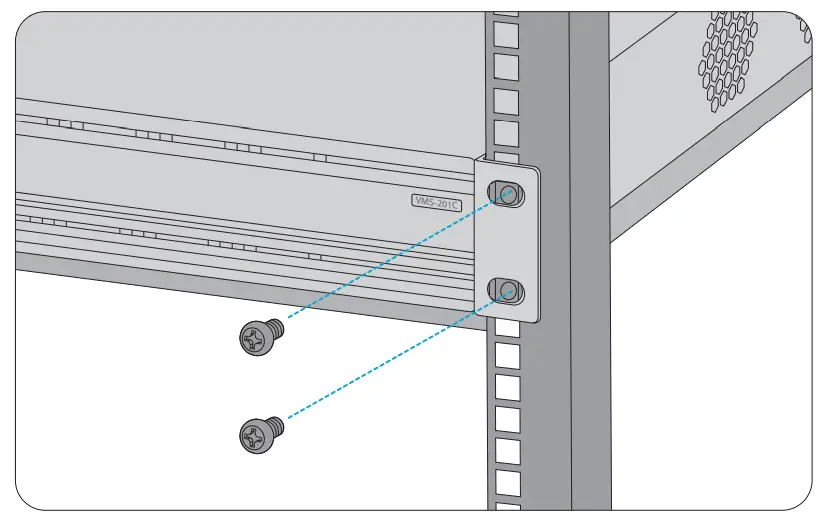
Install the device on a well grounded and securely installed rack. First install two mounting brackets on the device, and then secure the device on the rack by threading screws through the holes on the mounting brackets.
Configuring the switch
Start up
Please prepare a monitor and a keyboard. Connect the monitor, mouse, keyboard and then power.
Turn on the power switch on the back panel. The startup takes a while. Please wait patiently.
Login
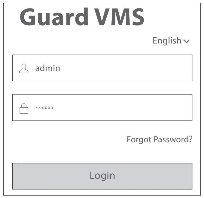
When the device is started, the login page appears. Use the default username admin and default password 123456 to log in to the software client. The software client is mainly used for service operations. Click the help link in the top right corner for help information. When logged in, you can click the Web icon in the top right corner to access the Web client. The Web client is mainly used for management and configuration purpose. Click the toolbar at the bottom to switch between the software client and Web client.
Restart
Right-click on the software client and then choose Restart, or access the Web client and click Restart on System Configuration>Maintenance>Maintenance.
Shutdown
Use the power switch on the back panel to shut down the device.
Online Resources
- Download https://www.fs.com/products_support.html
- Help Center https://www.fs.com/service/fs_support.html
- Contact Us https://www.fs.com/contact_us.html
Product Warranty
FS ensures our customers that any damage or faulty items due to our workmanship, we will offer a free return within 30 days from the day you receive your goods. This excludes any custom made items or tailored solutions.
 Warranty: The Video Management Server enjoys a 2-year limited warranty against defect in materials or workmanship. For more details about warranty, please check at: https://www.fs.com/policies/warranty.html
 Return: If you want to return item(s), information on how to return can be found at: https://www.fs.com/policies/day_return_policy.html
Q.C. PASSED
Copyright © 2022 FS.COM All Rights Reserved.

References
 FS.com - Data Center, Enterprise, Telecom
-
Contact Us - FS.com
-
Kontakt - FS.com Deutschland
-
Rückgaberecht - FS.com Deutschland
-
Ein weltweit führender Anbieter von Hochgeschwindigkeits-Konnektivitätsgeräten und -lösungen. - FS.com Deutschland
-
Technische Dokumente - FS.com Deutschland
-
Hilfezentrum - FS.com Deutschland
-
Comment Nous Contacter - FS.com France
-
Politique de retour - FS.com France
-
Fournisseur leader de solutions et matériels de connectivité à haut débit - FS.com France
-
Documents techniques - FS.com France
-
Centre d'aide - FS.com France
-
Return Policy - FS.com
-
Products Warranty - FS.com
-
Technical Documents - FS.com
-
Help Center - FS.com


