Wirebridge MG21USB Dongle
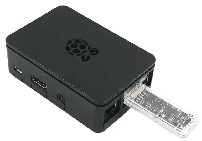
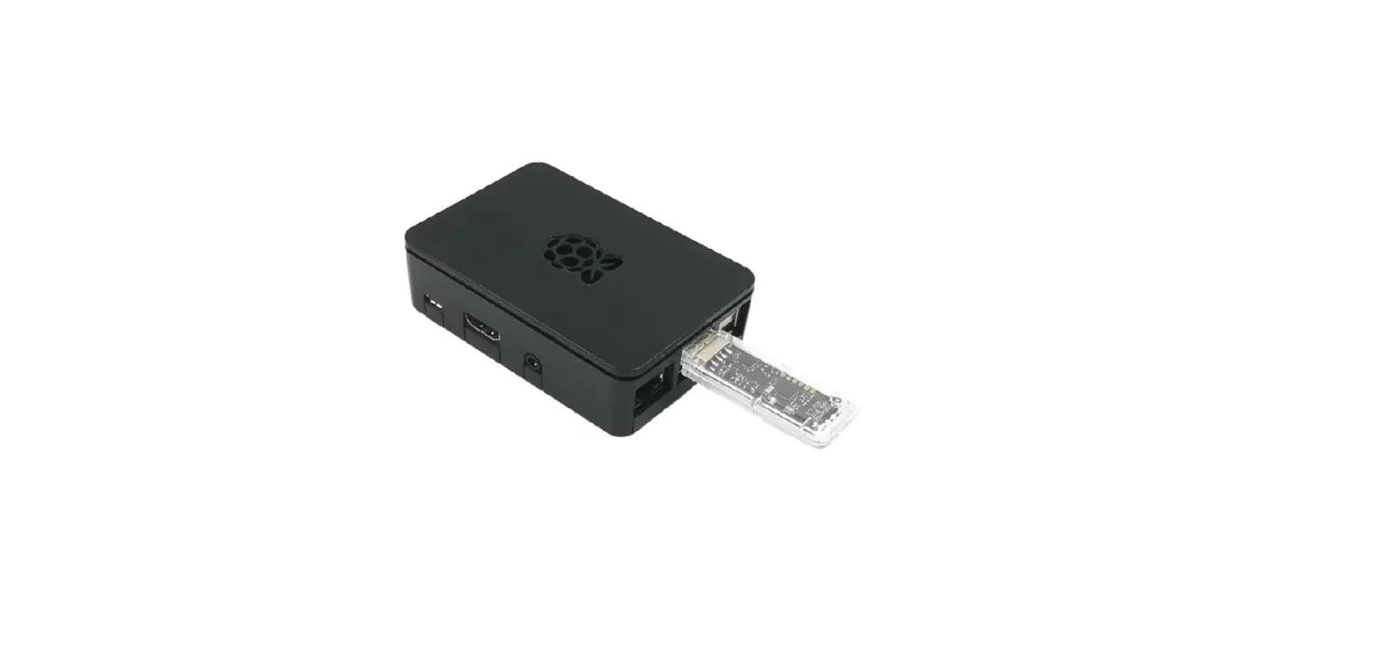
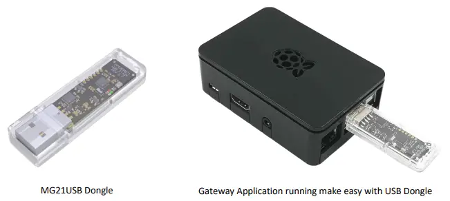
Wirebridge MG21USB Dongle is a low-cost and convenient kit for Zigbee gateway, OpenThread Border Router and Multi-PAN Zigbee/OpenThread concurrent multiprotocol gateway application evaluation and development. The MG21USB Dongle has included the Mini-Simplicity debugging and programming interface for USB Dongle firmware flashing, application debugging and PTI network traffic capture using the Simplicity Studio Network Analyzer utility.
KEY FEATURES
- MG21USB Dongle user guide
- USB Dongle firmware flashing
- USB Dongle SEGGER J-LINK SWD debugging
- USB Dongle PTI network capture
MG21USB Dongle Guide
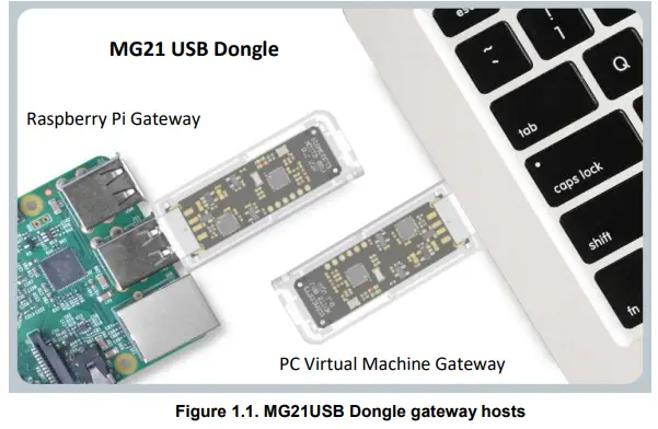
The MG21USB Dongle serves as an alternative low-cost hardware kit for Zigbee gateway, OpenThread Border Router, and Silicon Labs Multi-PAN RCP based Zigbee/OpenThread concurrent multi-protocol gateway Linux host application demo, evaluation and development purposes. Alternatively, it can be used as the harness test firmware USB dongle for ZUTH harness pre-testing of Zigbee devices in-house unofficially. The USB Dongle has equipped with EFR32MG21A020F1024IM32-B or EFR32MG21B020F1024IM32-B (MG21 +20dBm TX power, 96KB RAM,1024KB flash) and CP2102N-A02-GQFN24R UART-to-USB bridge IC for communication between Linux host over the USB port. Typically, a Raspberry Pi or a PC installed an Ubuntu Linux Virtual Machine is capable of running the IoT gateway host application.
Board Description
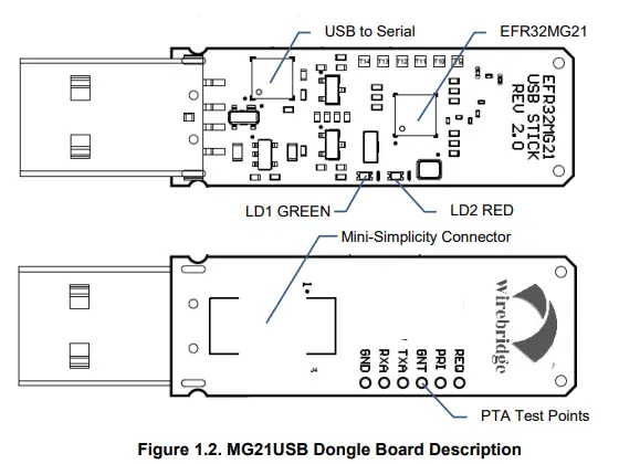
Please refer to below figure for the key component description on the USB Dongle board.
USB Dongle EFR32MG21 I/O Mapping
UART interface to a host
| Name | GPIO | Properties | Remark |
| EFR_TX | PA05 | Out, active-low | US0_TX |
| EFR_RX | PA06 | In, active-low | US0_RX |
| EFR_CTS | PA04 | In, active-low | US0_CTS |
| EFR_RTS | PC01 | Out, active-low | US0_RTS |
Bootloader mode pin
| Name | GPIO | Properties | Remark |
| NCP_BTL | PC02 | In, active-low | |
| EFR_RST | – | In, active-low |
PTA interface pins
| Name | GPIO | Properties | Remark |
| PTA_REQUEST | PC00 | Out, active-high, non-shared mode | |
| PTA_RIORITY | PB00 | Out, active-high, non-shared mode | |
| PTA_GRANTn | PB01 | In, active-low |
SWD Debug Interface pins
| Name | GPIO | Properties | Remark |
| SWCLK | PA01 | In | |
| SWDIO | PA02 | In/Out | |
| SWO | PA03 | Out |
PTI Capture and RF Debug pins
| Name | GPIO | Properties | Remark |
| FEM_TXA | PD02 | Out, active-high | LD2 (RED) |
| FEM_RXA | PD03 | Out, active-high | LD1 (GREEN) |
| PTI_DATA | PC04 | Out, active-low | |
| PTI_FRAME | PC05 | Out, active-low |
LFXO interface pins
| Name | GPIO | Properties | Remark |
| LFXTAL_O | PD00 | Analog out | 32.768KHz |
| LFXTAL_I | PD01 | Analog In | 32.768KHz |
USB Dongle and Host Interface
The on-board CP2102N UART-to-USB bridge IC provides the serial communication to the Linux host. Full UART (TX, RX, RTS, CTS) with hardware flow control and data transfer rate up to 3Mbps are supported.
USB Dongle Application FW Upgrade over USB through X-Modem Bootloader
The USB Dongle is factory pre-flashed with a X-Modem bootloader firmware which supports the BootLoad pin control. Host application may take advantage of the on-board CP2102N modem DTR and RTS pins to control MG21’s RESETn and NCP_BTL pins respectively. Host software may force reset MG21 into Bootloader mode for application image upgrade via XModem file-transfer protocol. This provides a fail-safe application upgrade scenario. Alternatively, the Z3GatewayHost sample application available in EmberZNet SDK provides the EZSP command to cause the Zigbee NCP application to software reboot into Bootloader mode without using the BootLoad and RESET pins. However, this command could be failed if current NCP application is corrupted somehow. A firmware loading tool can be available to USB dongle users by contacting with [email protected].
MG21 Bootloader mode and Reset control
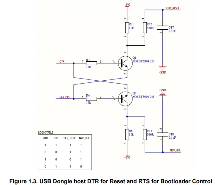
Instead of having the BOOTLOAD and RESET push buttons on board, the USB Dongle HW design (shown below) makes use of CP2102N’s modem control pins, i.e. DTS and RTS, for MG21 Reset control and entering the Bootloader mode.
This achieves fail-safe application firmware update for the MG21 USB Dongle by the host application even when the original NCP application firmware is corrupted somehow. Note that the host RTS control pin (EFR_CTS) is used for both Bootloader control and HW flow control purposes. HW flow control can still work in parallel and MG21 won’t false-enter Bootloader mode without the host DTR control triggers the Reset.
LED Indicators
Two LED indicators are provided for USB Dongle firmware application use:
- LD1 (GREEN): PD03 (FEM_RXA)
- LD2 (RED): PD02 (FEM_TXA)
PTA Debug Interface
The USB Dongle HW design has reserved the PTA Coexistence pins (REQUEST, PRIORITY, GRANT) and the RF debug FEM_TXA, FEM_RXA debug pins exposed to PTA debug test points, i.e. T9 to T14. Please refer to session 1.10 for the PTA test points description. To enable PTA, a Zigbee NCP or an OpenThread RCP sample project needs to install the Coexistence plugin and configure the PTA pins accordingly. FEM_TXA, FEM_RX are recommended to be enabled to helps the PTA debugging.
Using the Mini-Simplicity interface on USB Dongle
Factory default of the MG21 USB Dongle hasn’t the Mini-Simplicity connector J3 mounted. We recommend the Linux host to do MG21 application firmware upgrade over USB using X-Modem file transfer through the Bootloader, instead of using SEGGER J-Link SWD over the Mini-Simplicity debug interface. Developer is required to purchase a 10-pin (2×5) small form-factor (1.27mm pitch, 3.05mm pin length) header connector, similar to Samtec part number FTSH-105-01-L-DV-K with guide pin or FTS-105-01-L-DV-TR without guide pin. Then manually solder the header onto the USB Dongle PCB bottom side. Please note the pin-1 position of the Samtec connector with guide pin.
Blow shows the pin-out for the 10-pin Mini-Simplicity connector and connector pin-functions:
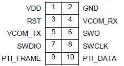
Note: Mini Simplicity Connector pin-out is referenced from the device target side.
| Pin # | Pin Name | Pin Function | EFR32 Functionality |
| 1 | VDD | 3.3V power supply to external EFR32 target | VDD |
| 2 | GND | Target Ground | VSS |
| 3 | RST | Target Reset (Active Low) | RESETn |
| 4 | VCOM_RX | Target Pass-through UART/Virtual COM Port Receive | US0_RX |
| 5 | VCOM_TX | Target Pass-through UART/Virtual COM Port Transmit | US0_TX |
| 6 | SWO | Target Serial Wire Output | SWO |
| 7 | SWDIO | Target Serial Wire Data Input/Output | SWDIO |
| 8 | SWCLK | Target Serial Wire Clock | SWCLK |
| 9 | PTI_FRAME | Target Packet Trace Interface Frame Signal | FRC_DFRAME |
| 10 | PTI_DATA | Target Packet Trace Interface Data Signal | FRC_DOUT |
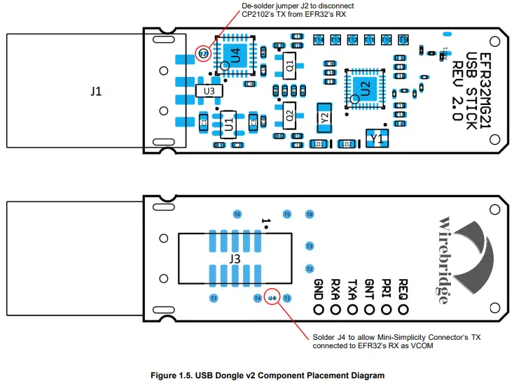
By default, USB Dongle’s MG21 VCOM_TX and VCOM_RX signals are directed to the CP2102N UART-to-USB bridge then to the host USB port. For Simplicity Studio to communicate with USB Dongle on-board MG21 VCOM UART through the Mini-Simplicity connector, it is required to de-solder solder-joint jumper J2 to disconnect CP2102 from MG21 and solder jumper J4 near the mini-simplicity header in figures shown on next page.
MG21 USB Dongle v2 Components Placement
Below shows the component placement of the MG21 USB Dongle and the corresponding test points
MG21 USB Dongle Test Points
Below tables show the PTA test points (T9-T14) and other test points, e.g. SWD interface factory used and reserved GPIO:
| Test Point | Signal | Description |
| T1 | PA00 | Free IO |
| T2 | PC03 | Free IO |
| T3 | PD04 | Free IO |
| T4 | GND | Ground |
| T5 | RESETn | Reset to EFR32 (active-low) |
| T6 | SWDIO | SEGGER J-LINK SWD data |
| T7 | SWDCLK | SEGGER J-LINK SWD clock |
| T8 | +3V3 | 3.3V power supply |
| T9/REQ | PC00 | PTA REQUEST |
| T10/PRI | PB00 | PTA PRIORITY |
| T11/GNT | PB01 | PTA GRANT |
| T12/TXA | PD02 | FEM TX Active debug signal |
| T13/RXA | PD03 | FEM RX Active debug signal |
| T14/GND | GND | Ground |
MG21 USB Dongle firmware flashing, debugging and PTI Network Traffic Capture
USB Dongle Firmware Flashing over X-Modem Bootloader (Recommended)
Refer to session 1.4 USB Dongle Application FW Upgrade over USB through X-Modem Bootloader and session 1.5 MG21 Bootloader mode and Reset control, an NCP/RCP firmware upgrade utility can be provided to upgrade the application firmware of MG21 USB Dongle over serial in X-Modem Bootloader (please contact [email protected]).
The firmware upgrade utility package will include:
- Document: fw_upgrade_utility_user_guide.md (instructions for compilation and FW upgrade)
- Source: usbstick_fw_upgrade_util_v0.2.tar.bz2
- Pre-built binaries:
- fw_upgrade_util_arm64.tar.bz2 (Raspberry Pi Ubuntu server 64-bit)
- fw_upgrade_util_x86-64.tar.bz2 (PC Ubuntu Linux 64-bit)
USB Dongle Firmware Flashing using WSTK + Simplicity Debug Adapter
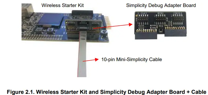
The Wireless Starter Kit main board (BRD4001A) with additional Simplicity Debug Adapter Board (SLSDA001A – MSRP USD 9.99) and 10-pin mini-simplicity ribbon cable are required to flash the USB Dongle firmware over the SEGGER J-LINK SWD debug interface.
Firmware Flashing over Mini-Simplicity Debug Interface
Connect the WSTK to PC USB port with the provided mini-USB cable. In Simplicity Studio, click the top toolbar![]() button to launch the Tools Dialog. Navigate and double-click to launch “Simplicity Commander”.
button to launch the Tools Dialog. Navigate and double-click to launch “Simplicity Commander”.
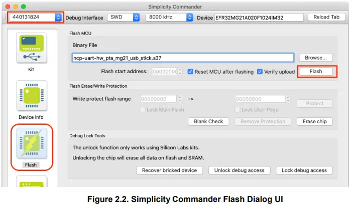
- From top toolbar, select the WSTK to connect to it.
- Click the ”Kit” dialog tab, make sure “OUT” is selected in “Debug mode”.
- Click top-right “Reload Tab” button to refresh, the external target device will be identified.
- Click the “Flash” dialog tab, browse the firmware .s37 or .bin file to be flashed and click “Flash” button to flash it to the external target device.
Reference: https://www.silabs.com/documents/public/user-guides/ug162-simplicity-commander-reference-guide.pdf
Source-level Debugging over Mini-Simplicity debug interface
Firstly, make sure “Simplicity Commander” has been quitted. Open the SoC application project in Simplicity Studio IDE and in the Debugger Adaptors window to connect the BGM220 Explorer Kit and the external EFR32 target for source code level debugging. For details, please refer to below: https://docs.silabs.com/simplicity-studio-5-users-guide/latest/ss-5-users-guide-testing-and-debugging/using-the-debugger
PTI Network Capture over Mini-Simplicity debug interface
Firstly, make sure “Simplicity Commander” has been quitted. In the Debugger Adaptors window to connect the BGM220 Explorer Kit and the external EFR32 target, and then launch the Network Analyzer from the Simplicity Studio. Connect to the external EFR32 target via the BGM220 Explorer Kit as SEGGER J-Link SWD Launch the Network in Simplicity Studio IDE for source code level debugging. For details, please refer to below:
In Simplicity Studio, click the top toolbar ![]() button to launch the Tools Dialog. Navigate and double-click to launch “Network Analyzer” for PTI Network capture. For details, please refer to QSG106 section 6 Using the Network Analyzer: https://www.silabs.com/documents/public/quick-start-guides/qsg106-efr32-zigbee-pro.pdf
button to launch the Tools Dialog. Navigate and double-click to launch “Network Analyzer” for PTI Network capture. For details, please refer to QSG106 section 6 Using the Network Analyzer: https://www.silabs.com/documents/public/quick-start-guides/qsg106-efr32-zigbee-pro.pdf
MG21USB Dongle Certifications
This section details the regulatory certification status of the MG21USB dongle in various regions. The address for the USB Dongle manufacturer and certification applicant is: WIREBRIDGE LTD. 71-75 Shelton Street, Covent Garden, London, United Kingdom, WC2H 9JQ.
CE and UKCA – EU and UK
The MG21USB Dongles have been tested against the relevant harmonized/designated standards and are in conformity with the essential requirements and other relevant requirements of the Radio Equipment Directive (RED) (2014/53/EU) and of the Radio Equipment Regulations (RER) (S.I. 2017/1206). Please notice that every end-product integrating a MG21 Dongle may need to perform the radio EMC tests on the whole assembly, according to the ETSI 301 489-x relevant standards. Furthermore, it is ultimately the responsibility of the manufacturer to ensure the compliance of the end-product as a whole. Manufacturers should carefully consider RF radiated testing with the final product assembly and the possible deviations in the PSD, EIRP and spurious emissions measurements, as defined in the ETSI 300 328 standard. The USB Dongles are entitled to carry the CE and UKCA Marks, and a formal Declaration of Conformity (DoC) is available at the product web page which is reachable starting from https://www.wirebridge.co.uk/.
FCC STATEMENT
This device complies with part 15 of the FCC Rules. Operation is subject to the following two conditions:
- This device may not cause harmful interference.
- This device must accept any interference received, including interference that may cause undesired operation.
Any Changes or modifications not expressly approved by the party responsible for compliance could void the user’s authority to operate the equipment.
Note: This equipment has been tested and found to comply with the limits for a Class B digital device, pursuant to part 15 of the FCC Rules. These limits are designed to provide reasonable protection against harmful interference in a residential installation. This equipment generates uses and can radiate radio frequency energy and, if not installed and used in accordance with the instructions, may cause harmful interference to radio communications. However, there is no guarantee that interference will not occur in a particular installation. If this equipment does cause harmful interference to radio or television reception, which can be determined by turning the equipment off and on, the user is encouraged to try to correct the interference by one or more of the following measures:
- Reorient or relocate the receiving antenna.
- Increase the separation between the equipment and receiver.
- Connect the equipment into an outlet on a circuit different from that to which the receiver is connected.
- Consult the dealer or an experienced radio/TV technician for help.
ISED – Canada
This device complies with Industry Canadas licence-exempt RSSs. Operation is subject to the following two conditions:
- This device may not cause interference.
- This device must accept any interference, including interference that may cause undesired operation of the device.
Document Revision History
Revision 2.0.0
Jan 14, 2022
- Split out original document to keep the MG21 USB Dongle user manual in this document
- Updated MG21USB Dongle figures to newer v2.0 hardware version
Revision 1.0.0
- Jul 16, 2021
- Initial release
FCC RF Exposure Information and Statement
The SAR limit of USA (FCC) is 1.6 W/kg averaged over one gram of tissue. Device types MG21USB Dongle (FCC ID: 2A6MQ-MG21USB) has also been tested against this SAR limit. The highest SAR value reported under this standard during product certification for use at the body is 0.073W/kg. This device was tested for typical body-worn operations with the back of the handset kept 0mm from the body. To maintain compliance with FCC RF exposure requirements, use accessories that maintain a 0mm separation distance between the user’s body and the back of the handset. The use of belt clips, holsters and similar accessories should not contain metallic components in its assembly. The use of accessories that do not satisfy these requirements may not comply with FCC RF exposure requirements and should be avoided.
Smart. Connected. Energy-friendly


