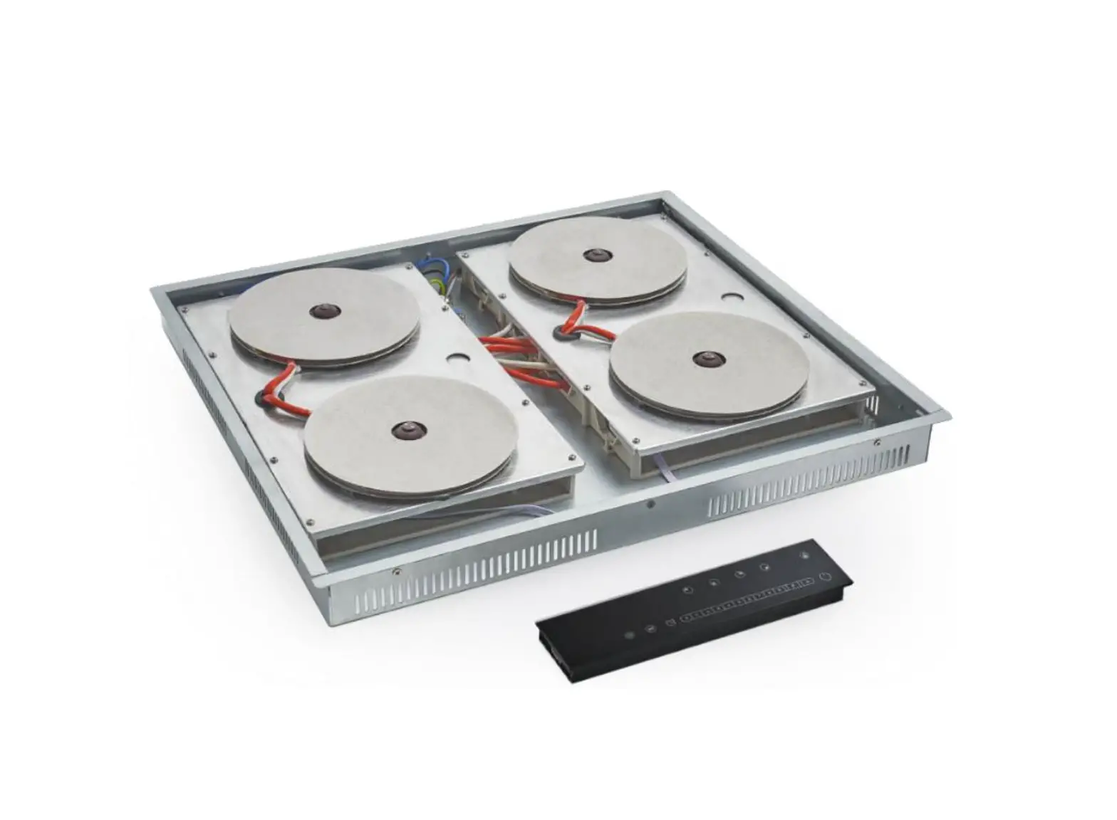
INVISACOOK Burner Electric Cooktop
DESCRIPTION
Thank you for your purchase of InvisaCook! Now let’s get ready to install it. There are many options, layouts and ways to install InvisaCook into your kitchen design, but we have 3 basic options for you, depending on the burner unit purchased. Please follow these directions and options for best results of your install and/or design.
Note: Directions provided by InvisaCook on installation of your unit are general instructions. If your Countertop Brand Manufacturer has other directions with regards to the installation, those must be followed to maintain the stone’s warranty.
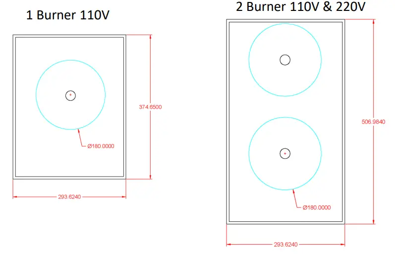
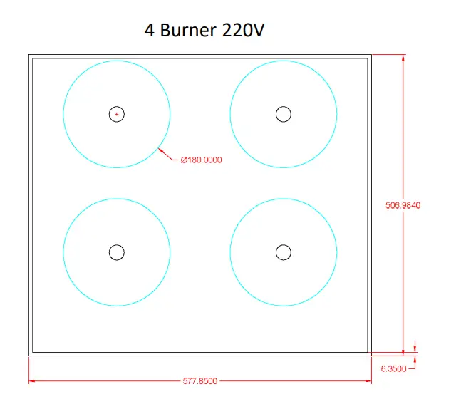
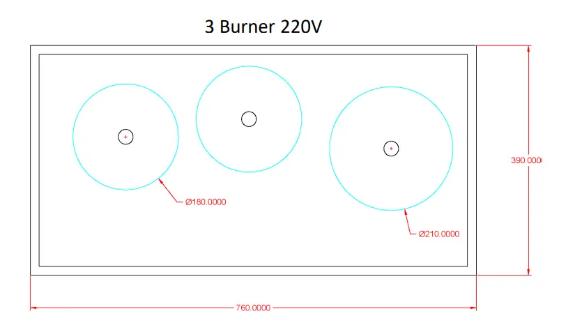
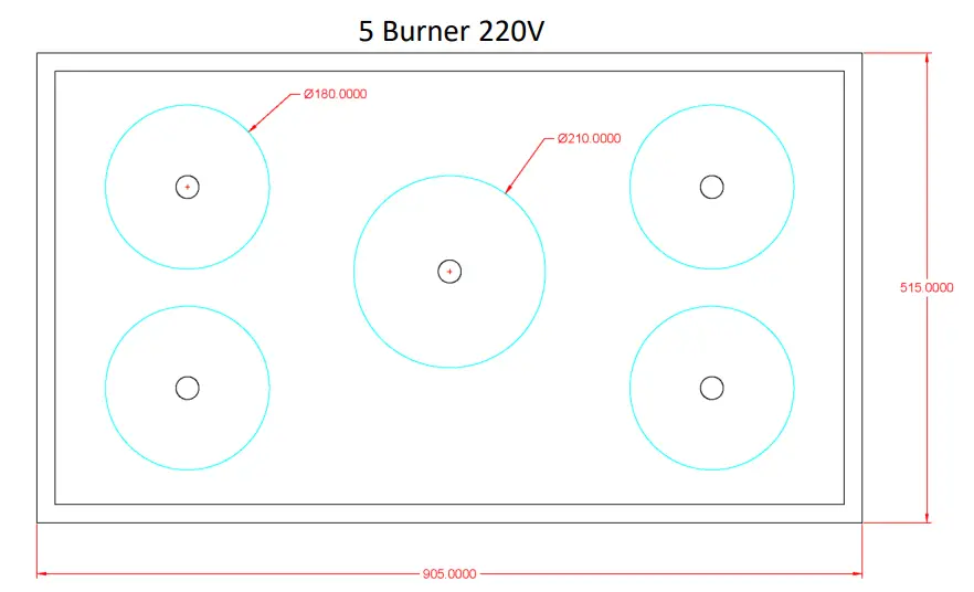
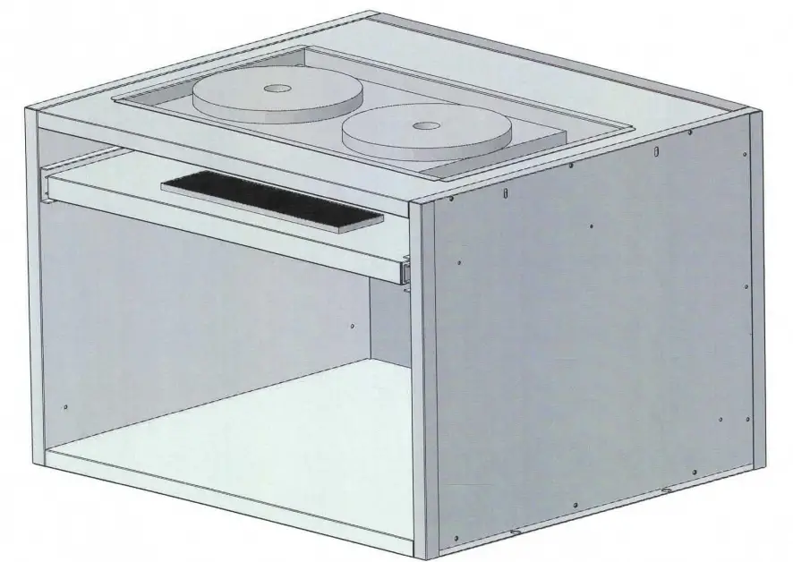
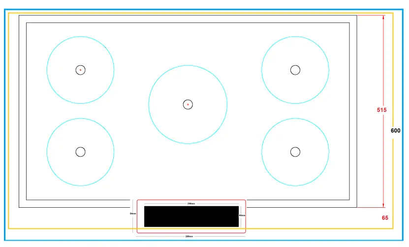
Dimensions of your Unit
STEP #1 Know what unit you are installing
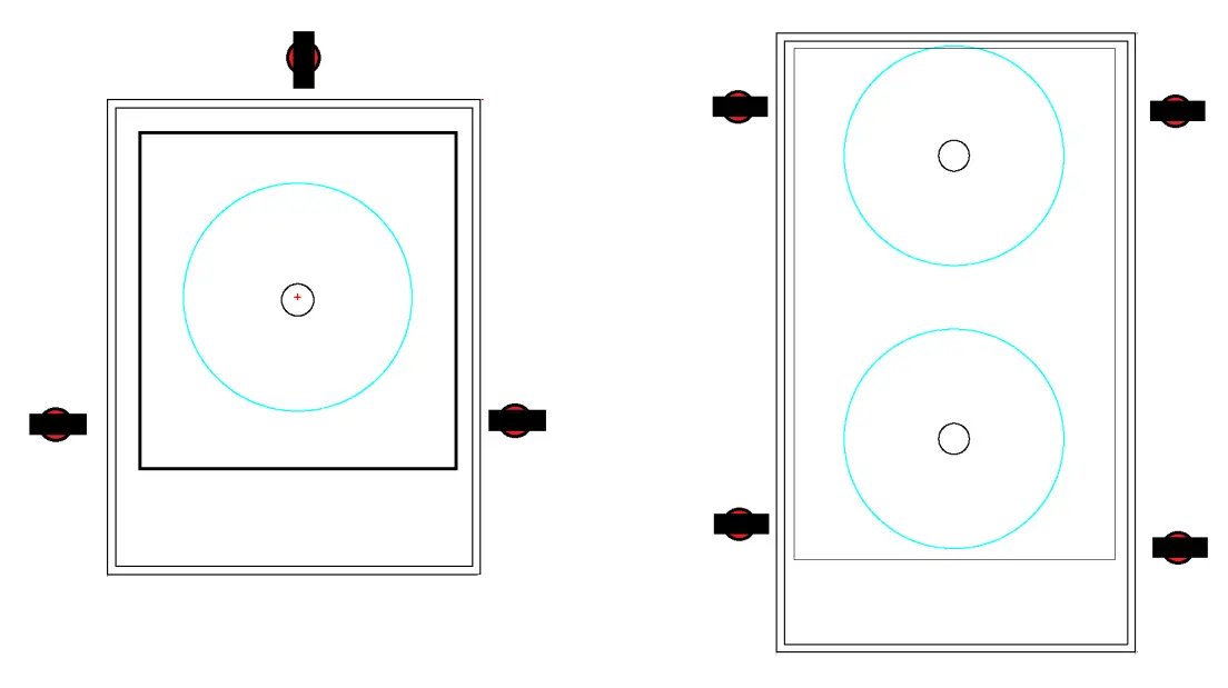
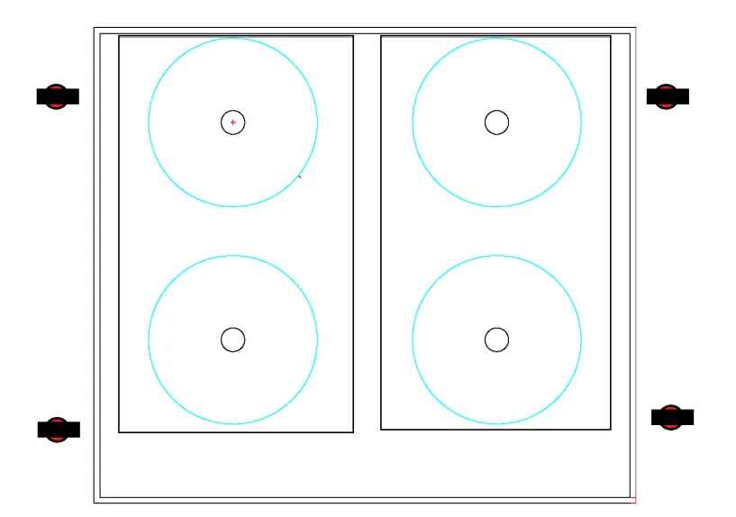
Sink Clip and Rail Option Layout
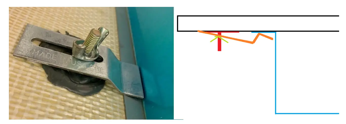
Step #2 If you are going to Install using sink Clips, ![]() here is the orientation of how the sink Clips should be installed
here is the orientation of how the sink Clips should be installed
If using Rail System, same edges apply to hold the unit up properly to the bottom of the surface.
Installation of Sink Clips and How to
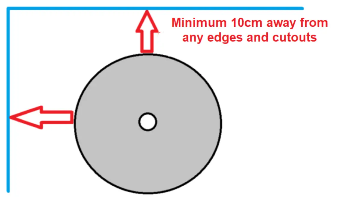
IMPORTANT NOTES FOR PROPER INSTALLATION BY GUIDANCE OF STONE MANUFACTURERS
- Burner are to be 10cm away from any open ends or Edges, see diagram below.
- All corners are to be round edges as instructed by the Materials Specification for their fabricated slabs.
- The use of the InvisaMAT (MUST ALWAYS BE USED) when operating the Invisacook system.
- Quality induction pots and pans must be used and were use for these test (Full-Clad Stainless Steel or Thick Stainless Steel Bottom pans)

Power Plugs, Power Cables, and Controller Cable Info
Installation With Sink Clips or Rail Notes:
When installing the Sink Clips, you can use a Seam Glue to Adhere the Sink Clips to the Countertop Surface, or a 2-part High Head JB-Weld, which might need 24 hours to cure before installation. – 12mm Porcelain with a back Meshing is preferred for the sink clip method, but not required.
NOTE: Meshing does not need to be removed in the area of the cooktop.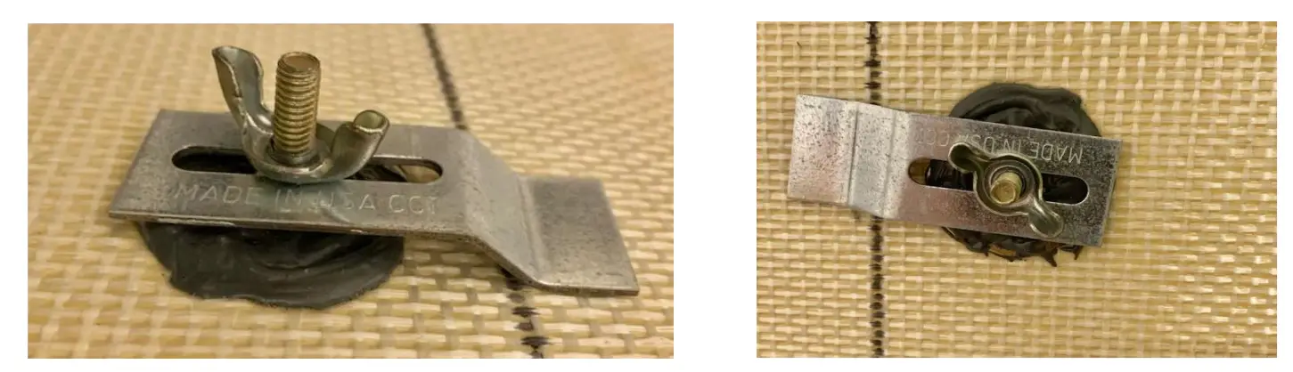
- See pictures below of properly adhered Sink Clips
- From this point, slide the unit into place, before fastening down the clip so it is secured.
- There should be no wiggle room at this point to the unit. Once securely fastened and tightened causes the the magneto nub on top of each burner to activate along with the temperature sensor for proper use.

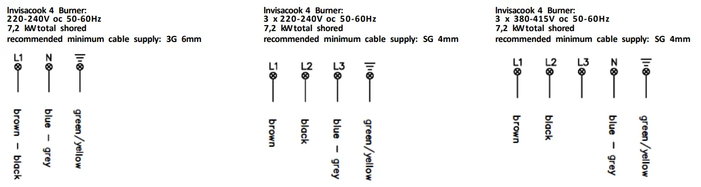
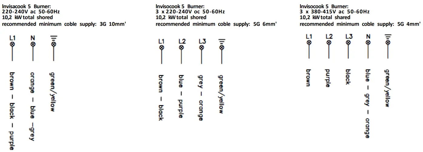
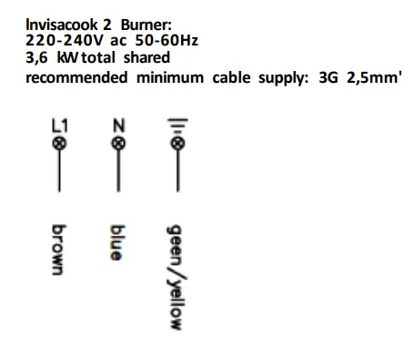
Hardwire Diagram and Directions
Plugs and Power Cables Info
All Power Cables are 140cm long in length and can be Hardwired, if taken off the plug or if country mandated or required.
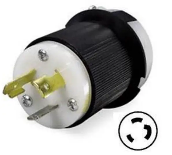
North America Units come with a Plug that is a Twistlock Plug. 30 Amp, 250 Volt, 2 Pole 3 Wire Grounding
- Solid Brass Blades & Receptacles
- Reinforced Ground Pins & Blades
- Hand Machined & Milled Parts
- Color Coded Wire Inserts

Hardwire Diagram and Directions
Controller Cables Info
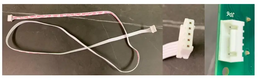
Controller Cables are made of UL2468 8 core AWM 2468 26AWG VW-1 80C 300V PVC Insulated Wire, with a male end of the cord to connect to the female end on the outside of controller box. All controller cables.
are 1.5 meters long (5500 cm)

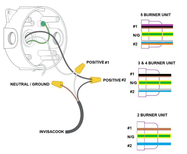
Hardwire Diagram and Info
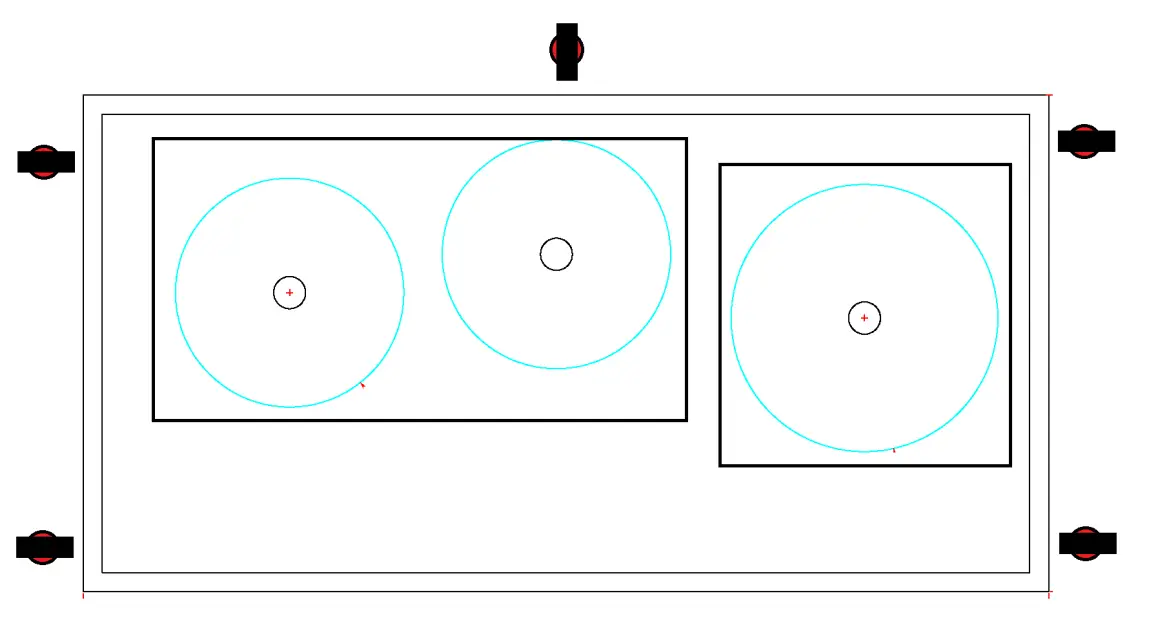
3 & 4 Burner Option
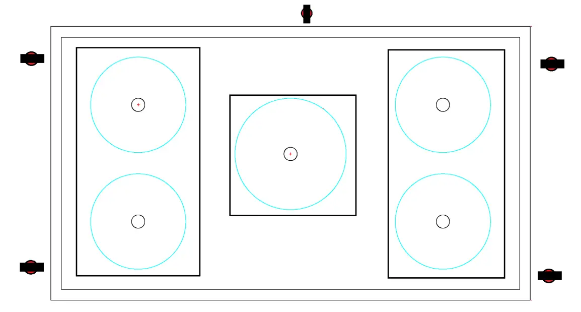
5 Burner Option
2 Burner Option
HARDWARE WIRE COMBINATION
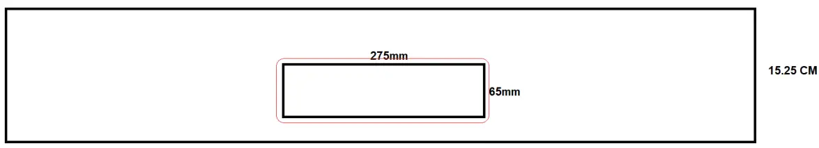
Drawer Slide Out Controller Option
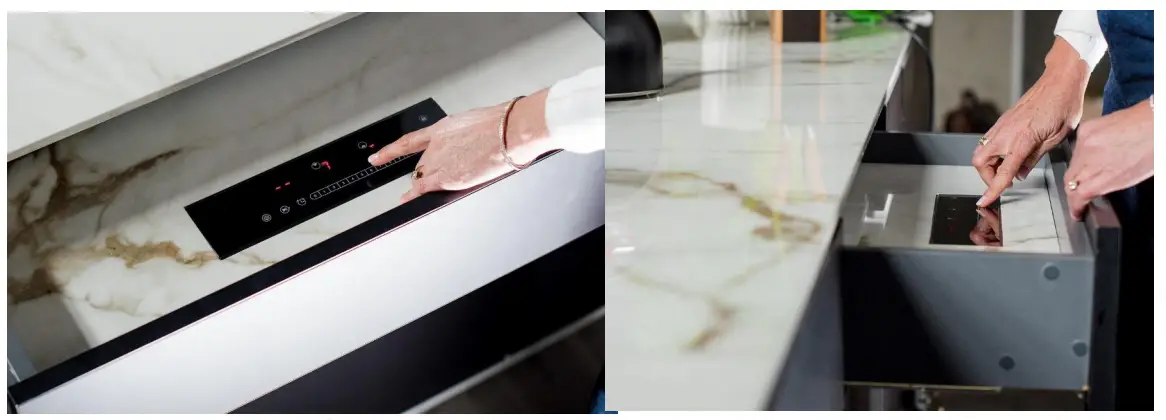
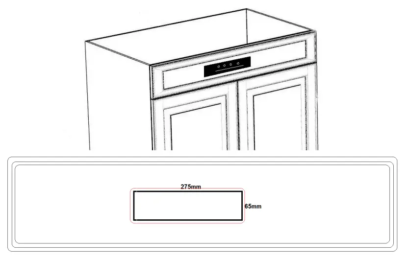
Drawer Size option depending on Cabinet width, with hole cutout size to drop in Controller in 15cm drawer or bottom of existing drawer.
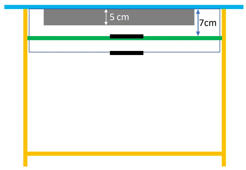
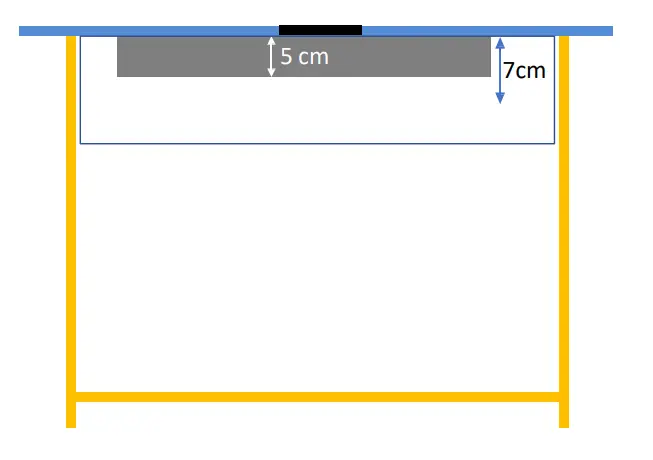
Cabinet Position when Installing in a Drawer in Drawer Option, Or Bottom Of Existing Drawer
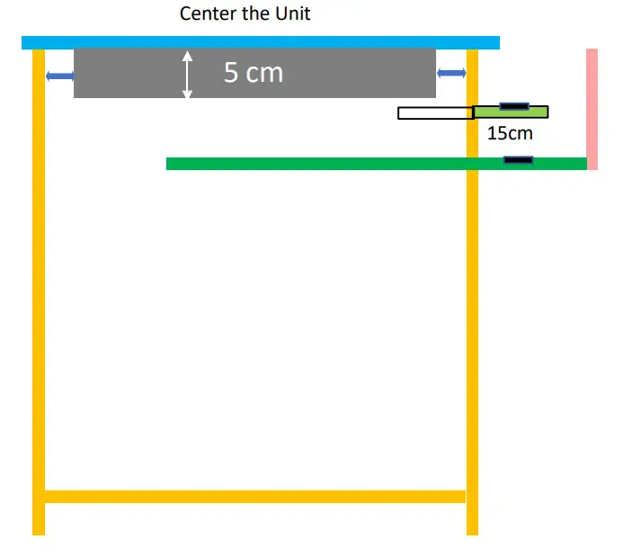
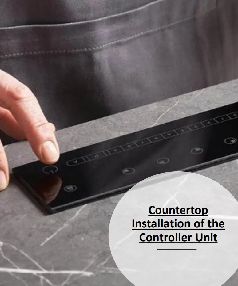
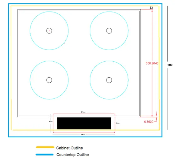
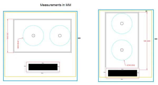
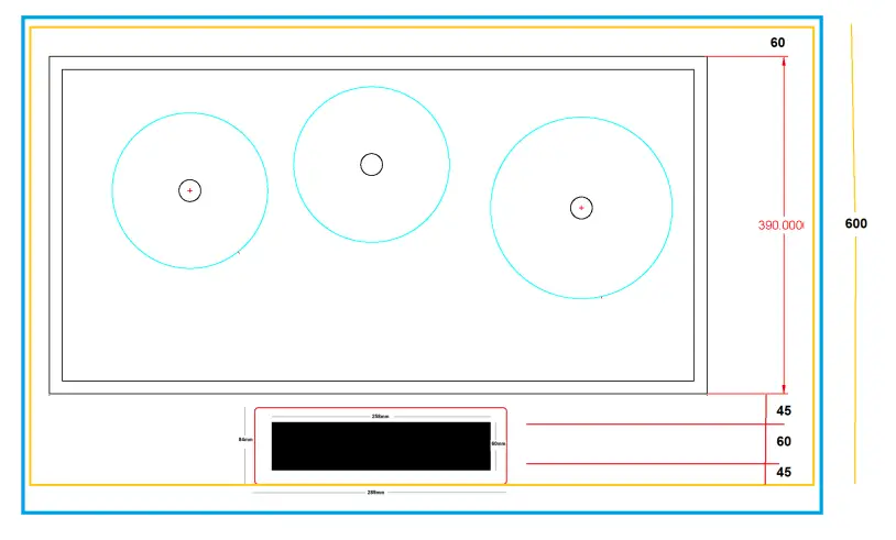
Cabinet Position when Installing on Countertop
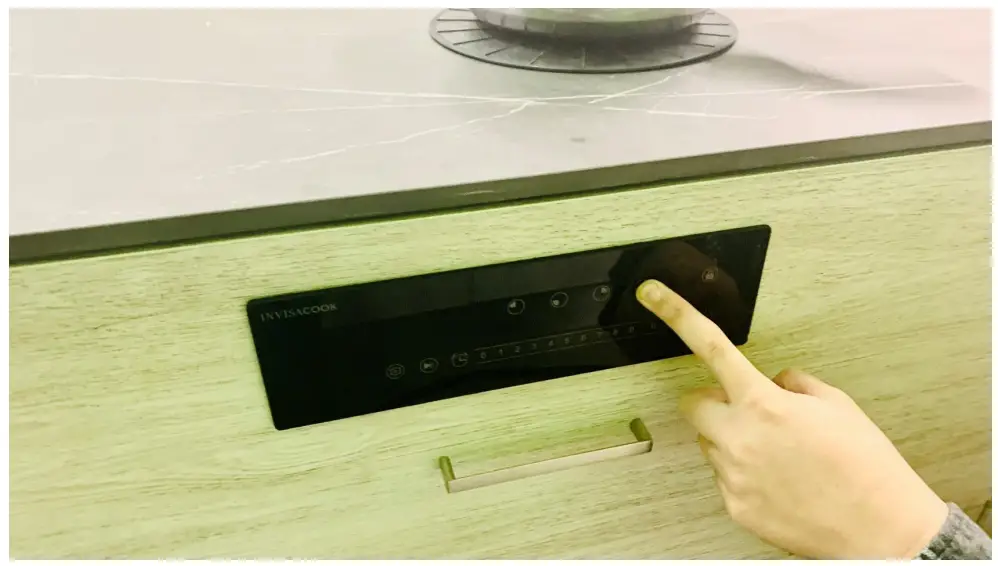
Cabinet Face Front Controller Installation
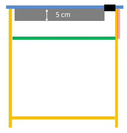
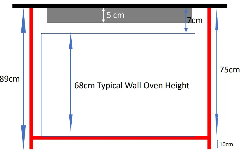
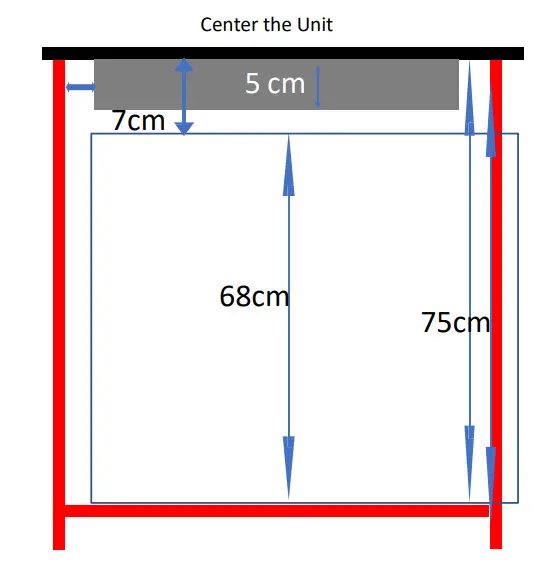
Cabinet Position when Installing a Wall Oven Under the InvisaCook Unit
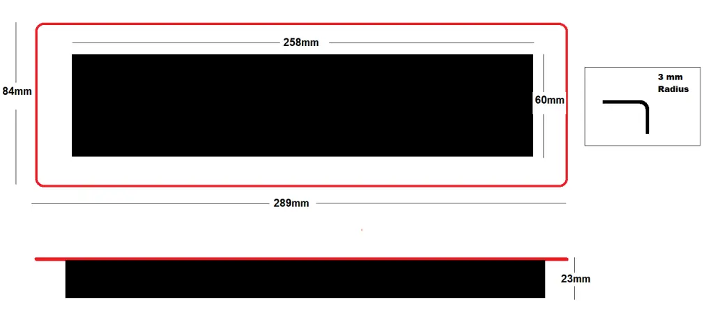
Controller Spec Drawing
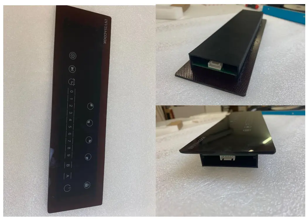
CONTROLLER FUNCTIONALITY
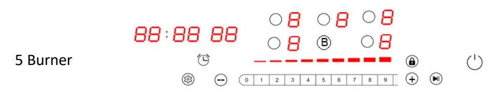
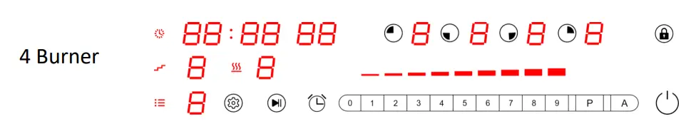
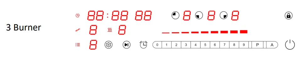
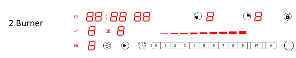
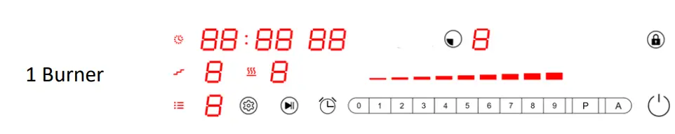
Basic Functions
Power on:
When power on, all the LED light 1s with beep, then go off, if working surface temperature over 60℃ on this model, the related digital LED will show “H”;and all the buttons are invalid except Power and Child Lock key.
ON/OFF:
Press power key to start stand by model, indicator lights, beep once, the related digital LED will show flashing “H” if it’s working surface temperature over 60℃, if not, the digital LED will show “-“.timer LED will show “–“. it will return to power on model if have not any operation within 2 min.press power key can also directly return to power on model.
Manual Mode(Power Selecting):
Press any burner key you want, now the zone is selected. When the zone is selected the power display will show “0” and start to blink. You can slide or press 0-9 to start working.
Lock:
To avoid any mis-operation and ensure safety of children. Press this button for 3s to enable the function, the indicator will light. All buttons are invalid except Child Lock and power key.
Booster:
Activate Booster = Select first the cooking zone and then press Booster, nowthe Booster will be activated, and the power display will show [ P ].
Deactivate Booster = Select first the cooking zone and then press booster, nowthe Booster will be deactivated, and the power display will return to previous power level.
Timer:
You can set the time max to 99minutes and this button can be activated only when burner is working . Press 0-9 keys to set timer.
Smart Functions:
Recording:
When Burner is working on Manual model (see above), long press the setting key ![]() , the device will record your cooking process(power level and cooking time).
, the device will record your cooking process(power level and cooking time).
Each time when you adjust the power level, the device will start a new step to record power level and cooking time,4 steps at most.
Press ![]() to finish recording or when the 4 steps recorded,it will finish recording automatically.
to finish recording or when the 4 steps recorded,it will finish recording automatically.
DIY Menu(programming)
On standby mode, long press setting key ![]() to amend/build the current menus, now the menu number
to amend/build the current menus, now the menu number ![]() LED will blink.
LED will blink.
Press 1-9 to select the menu you want to amend / build, short press ![]() to enter the menu, now the cooking step
to enter the menu, now the cooking step ![]() LED will blink.
LED will blink.
Repeat short press / can change to power level and cooking time(M:S) setting, this can change in a
cycle: from ![]() to
to ![]() to
to ![]() to
to ![]() …
…
Cooking step: all in 4 steps, power level: can be 1-9,cooking time: max to 99s:99s.When you finish setting, long press ![]() to save.
to save.
Auto Mode:
Auto cooking:
On standby mode, select one burner, press ![]() to enter auto cooking mode, now the burner LED will show ”A,” now the menu number will blink (press
to enter auto cooking mode, now the burner LED will show ”A,” now the menu number will blink (press ![]() again can return to last step).
again can return to last step).
Press 1-9 to select menu, press ![]() to start working, the food will be ready automatically (press can
to start working, the food will be ready automatically (press can ![]() stop cooking and select menu again).
stop cooking and select menu again).
There will be a point at lower right corner to remind the menu belongs to current burner.
Pre-set for menu:
On auto cooking mode, when you select menu number, press ![]() to pre-set, now the
to pre-set, now the ![]() LED will blink.
LED will blink.
Press 0-9 to set time, max can be 99h:99m.
Press ![]() to start pre-set, when time is up, the device will cook automatically.
to start pre-set, when time is up, the device will cook automatically.
Units Power and Consumption
5 Burner Unit 220V
Top Left : Nominal Power: 1000W(LEVEL 9) /1200W(Boost) Bottom Left: Nominal Power: 1000W(LEVEL 9) /1200W(Boost) Middle: Nominal Power: 1300W(LEVEL 9) /1500W(Boost) Top Right : Nominal Power: 1000W(LEVEL 9) /1200W(Boost) Bottom Right: Nominal Power: 1000W(LEVEL 9) /1200W(Boost Max power for four is 5,600w.
| 5 Burner Unit | |||||||||||
| Levels | L-Top B | L-Lower B | Levels | Levels | Large M | Levels | R-Top B | R-Lower B | Levels | ||
| P | 1200W | 0-W | 0 | P | 1500W | P | 1200W | 0-W | 0 | ||
| 9 | 1000W | 600W | 1 | 9 | 1300W | 9 | 1000W | 600W | 1 | ||
| 8 | 950W | 650W | 2 | 8 | 1200W | 8 | 950W | 650W | 2 | ||
| 7 | 900W | 700W | 3 | 7 | 1100W | 7 | 900W | 700W | 3 | ||
| 6 | 850W | 750W | 4 | 6 | 1000W | 6 | 850W | 750W | 4 | ||
| 5 | 800W | 800W | 5 | 5 | 900W | 5 | 800W | 800W | 5 | ||
| 4 | 750W | 850W | 6 | 4 | 800W | 4 | 750W | 850W | 6 | ||
| 3 | 700W | 900W | 7 | 3 | 700W | 3 | 700W | 900W | 7 | ||
| 2 | 650W | 950W | 8 | 2 | 600W | 2 | 650W | 950W | 8 | ||
| 1 | 600W | 1000W | 9 | 1 | 500W | 1 | 600W | 1000W | 9 | ||
| 0 | 0-W | 1200W | P | 0 | 0-W | 0 | 0-W | 1200W | P | ||
4 Burner Unit 220V
Top Left : Nominal Power: 1000W(LEVEL 9) /1200W(Boost)
Bottom Left: Nominal Power: 1000W(LEVEL 9) /1200W(Boost)
Middle: Nominal Power: 1300W(LEVEL 9) /1500W(Boost)
Top Right : Nominal Power: 1000W(LEVEL 9) /1200W(Boost)
Bottom Right: Nominal Power: 1000W(LEVEL 9) /1200W(Boost
Max power for four is 4,000w
| 4 Burner Unit | ||||||||
| Levels | L-Top B | L-Lower B | Levels | Levels | R-Top B | R-Lower B | Levels | |
| P | 1200W | 0-W | 0 | P | 1200W | 0-W | 0 | |
| 9 | 1000W | 600W | 1 | 9 | 1000W | 600W | 1 | |
| 8 | 950W | 650W | 2 | 8 | 950W | 650W | 2 | |
| 7 | 900W | 700W | 3 | 7 | 900W | 700W | 3 | |
| 6 | 850W | 750W | 4 | 6 | 850W | 750W | 4 | |
| 5 | 800W | 800W | 5 | 5 | 800W | 800W | 5 | |
| 4 | 750W | 850W | 6 | 4 | 750W | 850W | 6 | |
| 3 | 700W | 900W | 7 | 3 | 700W | 900W | 7 | |
| 2 | 650W | 950W | 8 | 2 | 650W | 950W | 8 | |
| 1 | 600W | 1000W | 9 | 1 | 600W | 1000W | 9 | |
| 0 | 0-W | 1200W | P | 0 | 0-W | 1200W | P | |
3 Burner Unit 220V
Left : Nominal Power: 1000W(LEVEL 9) /1200W(Boost)
Middle Left: Nominal Power: 1000W(LEVEL 9) /1200W(Boost)
Large Right: Nominal Power: 1300W(LEVEL 9) /1500W(Boost)
Max power for four is 3,600w
| 3 Burner Unit | ||||||
| Levels | Left Corner | Middle | Levels | Levels | Larger R | |
| P | 1200W | 0-W | 0 | P | 1500W | |
| 9 | 1000W | 600W | 1 | 9 | 1300W | |
| 8 | 950W | 650W | 2 | 8 | 1200W | |
| 7 | 900W | 700W | 3 | 7 | 1100W | |
| 6 | 850W | 750W | 4 | 6 | 1000W | |
| 5 | 800W | 800W | 5 | 5 | 900W | |
| 4 | 750W | 850W | 6 | 4 | 800W | |
| 3 | 700W | 900W | 7 | 3 | 700W | |
| 2 | 650W | 950W | 8 | 2 | 600W | |
| 1 | 600W | 1000W | 9 | 1 | 500W | |
| 0 | 0-W | 1200W | P | 0 | 0-W | |
2 Burner Unit 220V
Top : Nominal Power: 1000W(LEVEL 9) /1200W(Boost)
Bottom: Nominal Power: 1000W(LEVEL 9) /1200W(Boost)
Max power for four is 2,000w
| 2 Burner 220V | |||
| Levels | Top B | Lower B | Levels |
| P | 1200W | 0-W | 0 |
| 9 | 1000W | 600W | 1 |
| 8 | 950W | 650W | 2 |
| 7 | 900W | 700W | 3 |
| 6 | 850W | 750W | 4 |
| 5 | 800W | 800W | 5 |
| 4 | 750W | 850W | 6 |
| 3 | 700W | 900W | 7 |
| 2 | 650W | 950W | 8 |
| 1 | 600W | 1000W | 9 |
| 0 | 0-W | 1200W | P |
1 & 2 Burner Unit 110V are on North American Standard Plug and outlet.