![]() EVCO S.p.A.
EVCO S.p.A.
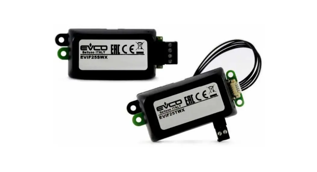
EVlinking Wi-Fi
Wi-Fi Module
EVlinking Wi-Fi
Installer manual ver. 4.1
Code 144IF25TWXE414 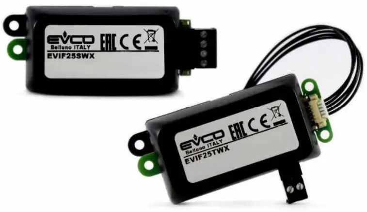
144IF25TWXE414 EVlinking Wi-Fi Advanced Controllers
![]() PLEASE READ CAREFULLY and save this document CONSIDER THE ENVIRONMENT
PLEASE READ CAREFULLY and save this document CONSIDER THE ENVIRONMENT![]() IMPORTANT
IMPORTANT
Read this document carefully before installation and before using the device and take all the prescribed precautions. Keep this document with the device for future consultation. Only use the device in the ways described in this document.
INTRODUCTION
1.1 Initial information
EVlinking Wi-Fi is a hardware module with Wi-Fi connectivity that can be connected to our EPoCA compatible controllers to access the functions of the EPoCA cloud platform or those of other control or data acquisition systems using the MODBUS TCP protocol.
The EVlinking Wi-Fi module can also be connected to third-party devices using the MODBUS RTU protocol on the RS-485 port to allow integration with client systems.
1.2 Main features
| Purchasing code | EVIF25TWX | EVIF25SWX |
| Power supply | controller-powered (depending on the type of controller) or independently powered 12 VAC/15 VDC | controller-powered (depending on the type of controller) or independently powered 12 VAC/15 VDC |
| Clock | • | • |
| Communications port | TTL MODBUS | RS-485 MODBUS |
N.B.
The compatibility of the controller with the EPoCA system and the possibility of powering EVlinking Wi-Fi from the controller depend on the type of controller. See the document “EPoCA – List of compatible controllers” available on the website www.evco.it and/or the label on the controller.
1.3 Schematic diagram 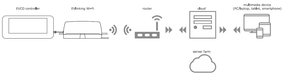
DESCRIPTION
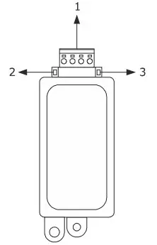
2.1 Description EVIF25TWX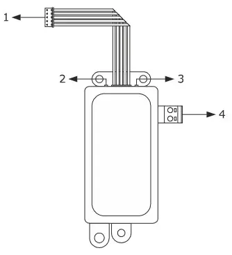
| Part | Description |
| 1 | Pico-Blade connector (TTL MODBUS port) |
| 2 | Red LED (MODBUS communication status) |
| 3 | Green LED (Wi-Fi communication status) |
| 4 | Plug-in screw terminal block (independent power supply) |
2.2 Description EVIF25SWX
| Part | Description |
| 1 | Plug-in screw terminal block (RS-485 MODBUS port) |
| 2 | Red LED (MODBUS communication status) |
| 3 | Green LED (Wi-Fi communication status) |
MEASUREMENTS AND INSTALLATION
Measurements in mm (inches); to be fitted to a hard surface with a cable tie (not provided).
3.1 Measurements and installation EVIF25TWX  3.2 Measurements and installation EVIF25SWX
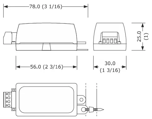 INSTALLATION PRECAUTIONS
– Ensure that the working conditions are within the limits stated in the TECHNICAL SPECIFICATIONS section
– Install the device where the Wi-Fi signal is strong
– Do not install the device close to metal parts which may impede Wi-Fi communication
– Do not install the device close to heat sources, equipment with a strong magnetic field, in places subject to direct sunlight, rain, damp, excessive dust, mechanical vibrations or shocks
– In compliance with safety regulations, the device must be installed properly to ensure adequate protection from contact with electrical parts. All protective parts must be fixed in such a way as to need the aid of a tool to remove them
ELECTRICAL CONNECTION
![]() N.B.
N.B.
– The compatibility of the controller with the EPoCA system and the possibility of powering EVlinking Wi-Fi from the controller depend on the type of controller. See the document “EPoCA – List of compatible controllers” available on the website www.evco.it and/or the label on the controller
– Do not power more than one EVlinking Wi-Fi with the same power supply
– If EVlinking Wi-Fi is to be independently powered, do not power it with the same power supply as the controller connected to EVlinking Wi-Fi
– The battery of EVlinking Wi-Fi is charged by the power supply of the device or by the independent power supply: for correct operation, the battery must be fully charged at least once a year
– To reduce any electromagnetic interference, locate the power cables as far away as possible from the signal cables
4.1 Example of controller label 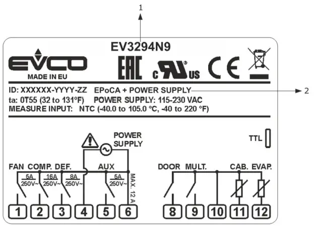
| Part | Description | |
| 1 | Purchasing code | |
| 2 | Additional information | |
| Abbreviation | Meaning | |
| EPoCA + POWER SUPPLY | The controller is compatible with the EPoCA system and is able to power EVIinking Wi-Fi | |
| EPoCA + EXT. POWER SUPPLY | The controller is compatible with the EPoCA system but the EVlinking Wi-Fi module must be independently powered | |
4.2 Electrical connection of EVIF25TWX to a controller able to power EVlinking Wi-Fi 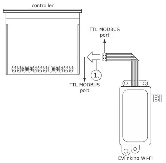 1. Connect the TTL MODBUS port on the EVlinking Wi-Fi to the TTL MODBUS port on the controller.
Before powering up the controller, see the section FIRST-TIME USE.
4.3 Electrical connection of EVIF25TWX to a controller unable to power EVlinking Wi-Fi 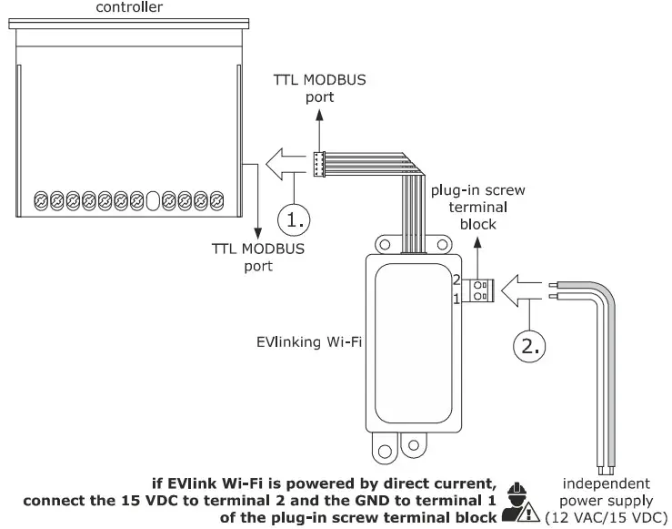
- Connect the TTL MODBUS port on the EVlinking Wi-Fi to the TTL MODBUS port on the controller.
- 2.1 Connect the end of an independent power supply cable to terminal 1 of the plug-in screw terminal block on EVlinking Wi-Fi.
2.2 Connect the end of the other independent power supply cable to terminal 2 of the plug-in screw terminal block on EVlinking Wi-Fi.
Before powering up the controller and EVlinking Wi-Fi, see the section FIRSTTIME USE.
4.4 Electrical connection of EVIF25SWXto a controller able to powerEVlinking Wi-Fi![]() N.B.
N.B.
– Connect the RS-485 using a twisted pair
– The maximum permitted length of the RS-485 connection cables is 1000 m (3280 ft) and enables EVlinking Wi-Fi to be installed in the most convenient place. Make sure that the voltage supplied to EVlinking Wi-Fi is within the limits set in the section TECHNICAL SPECIFICATIONS 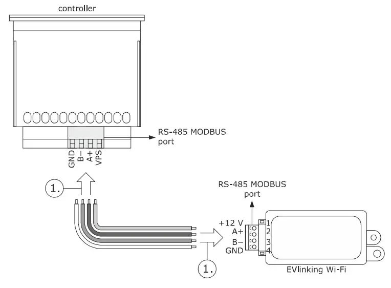
- 1.1 Connect terminal 4 of the EVlinking Wi-Fi RS-485 MODBUS (GND) port to the GND terminal of the RS-485 MODBUS port of the controller.
1.2 Connect terminal 3 of the EVlinking Wi-Fi RS-485 MODBUS (B-) port to the B- terminal of the RS-485 MODBUS port of the controller.
1.3 Connect terminal 2 of the EVlinking Wi-Fi RS-485 MODBUS (A+) port to the A+ terminal of the RS-485 MODBUS port of the controller.
1.4 Connect terminal 1 of the EVlinking Wi-Fi RS-485 MODBUS (+12 V) port to a terminal on the controller that is able to supply 12 VAC/15 VDC (VPS).
Before powering up the controller and EVlinking Wi-Fi, see the section FIRSTTIME USE.
4.5 Electrical connection of EVIF25SWX to a controller unable to power EVlinking Wi-Fi![]() N.B.
N.B.
Connect the RS-485 using a twisted pair 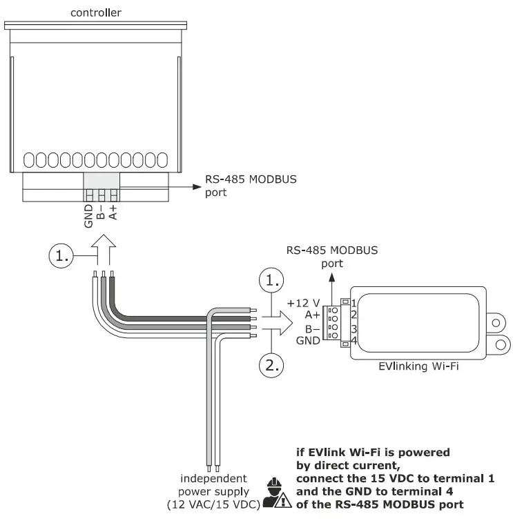
- 1.1 Connect terminal 4 of the EVlinking Wi-Fi RS-485 MODBUS (GND) port to the GND terminal of the RS-485 MODBUS port of the controller.
1.2 Connect terminal 3 of the EVlinking Wi-Fi RS-485 MODBUS (B-) port to the B- terminal of the RS-485 MODBUS port of the controller.
1.3 Connect terminal 2 of the EVlinking Wi-Fi RS-485 MODBUS (A+) port to the A+ terminal of the RS-485 MODBUS port of the controller. - 2.1 Connect terminal 4 of the EVlinking Wi-Fi RS-485 MODBUS (GND) port to the end of an independent power supply cable.
2.2 Connect terminal 1 of the EVlinking Wi-Fi RS-485 MODBUS (+12 V) port to the end of the other independent power supply cable.
Before powering up the controller and EVlinking Wi-Fi, see the section FIRST- TIME USE.
PRECAUTIONS FOR ELECTRICAL CONNECTION
– If the device is moved from a cold to a warm place, humidity may cause condensation to form inside. Wait for about an hour before connecting it to the controller or the independent power supply
– Disconnect the device from the controller or the independent power supply before carrying out any type of maintenance
– For repairs and for further information, contact the EVCO sales network
FIRST-TIME USE
![]() N.B.
N.B.
– EVlinking Wi-Fi uses an encrypted connection with TLS technology and occupies the TCP 8883 port. Make sure this firewall port (both the port of the user’s local network and the one managed by the Internet service provider) is open for outgoing communications (contact the IT manager)
– Ensure the user has a multimedia device (PC/laptop, tablet, smartphone) with a web browser installed and that the device is able to upload and download files. If the device has an iOS operating system, files can only be uploaded and downloaded if the user has an iCloud account and if access to this service has previously been made with the device
– Ensure the Wi-Fi on the device is on
5.1 First-time use of EVlinking Wi-Fi
- Power up the controller and make sure the bLE parameter (enable EVlinking) is set to 1; see the controller instructions.
- Disconnect the controller.
- Carry out the installation of EVlinking Wi-Fi as shown in the section MEASUREMENTS AND INSTALLATION.
- Connect EVlinking Wi-Fi as shown in the section ELECTRICAL CONNECTION.
- Power up the controller and connect the independent EVlinking Wi-Fi power supply, if used, to the power source.
-EVlinking Wi-Fi will be in temporary set-up mode. During this mode:
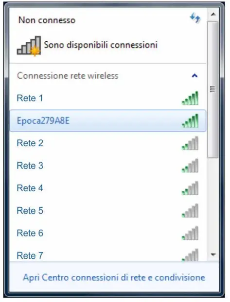
EVlinking Wi-Fi acts as both an access point (identifying a Wi-Fi network called Epoca followed by 6 alphanumeric characters, for example Epoca279A8E) and a data logger for the connected controller
– there is no connection with the cloud server.
After 120 s (600 for the first-time use) in set-up mode, EVlinking WiFi will automatically go into run mode if the control panel has not been accessed (point 9 of this paragraph). During this mode:
– EVlinking Wi-Fi acts as a data logger for the connected controller
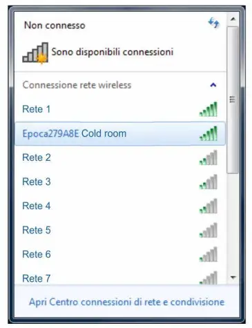
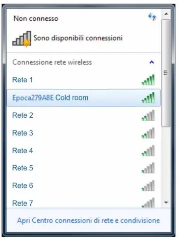
– there is no connection with the cloud server. - Scan the Wi-Fi networks using the multimedia device and identify a network called Epoca followed by 6 alphanumeric characters.
 If the scan detects more than one network called Epoca, make sure only one EVlinking Wi-Fi is being powered.
 - Connect to the Epoca network.
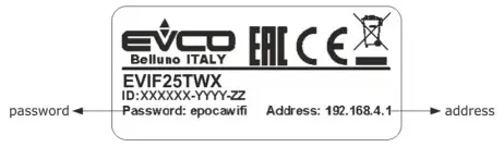
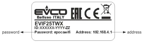
In the Security key field enter the password found on the label of the EVlinking Wi-Fi (typically epocawifi). - Open the web browser on the multimedia device.
Enter the address found on the label of the EVlinking Wi-Fi (typically 192.168.4.1) in the address bar.
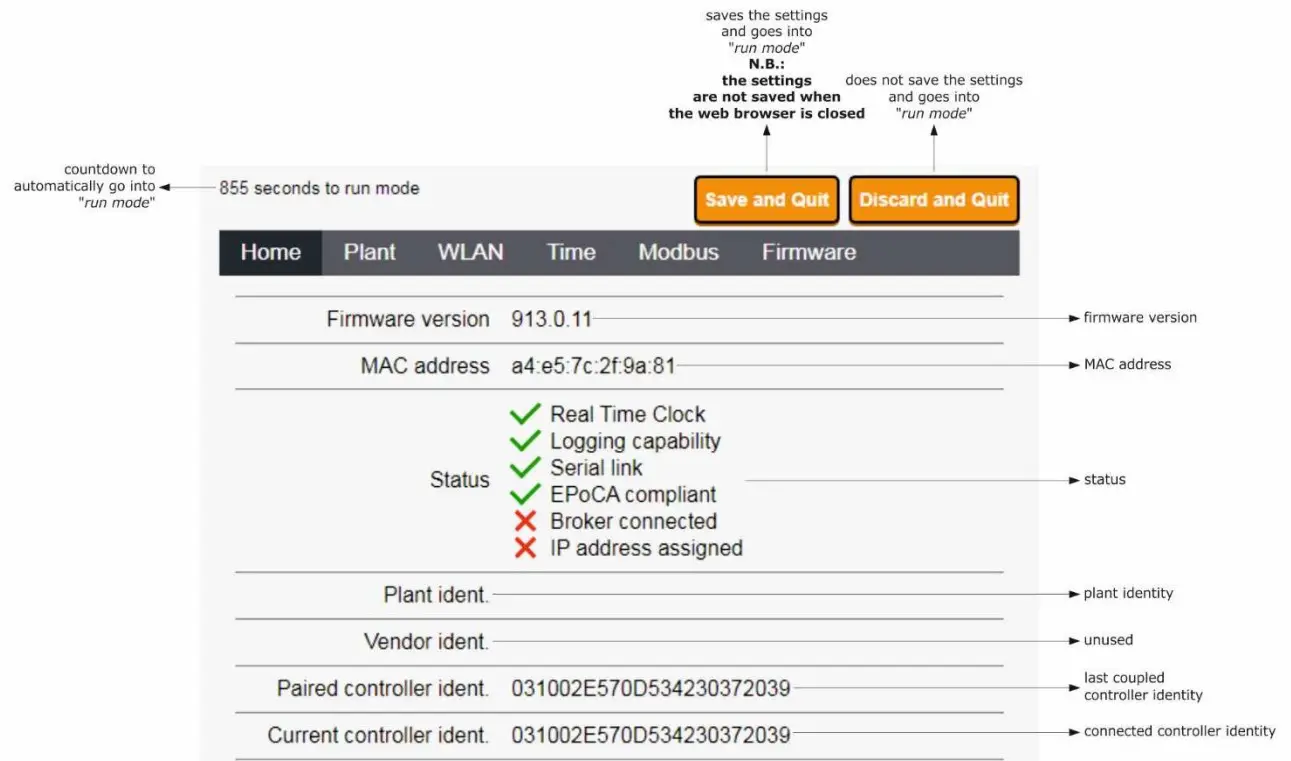
- The Home screen of the EVlinking Wi-Fi control panel will be displayed.
EVlinking Wi-Fi will be in temporary set-up mode. During this mode:
– EVlinking Wi-Fi acts as an access point but it cannot be accessed with another multimedia device
– there is no connection with the cloud server.
After 5 min in set-up mode, EVlinking Wi-Fi will automatically go into run mode if the control panel has not been accessed.
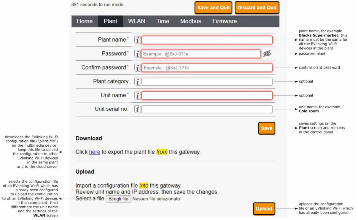
- Select the Plant screen on the EVlinking Wi-Fi control panel. The fields in red are mandatory.

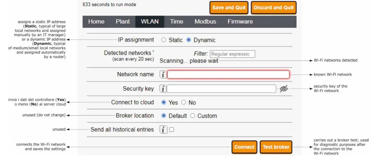
- Select the WLAN screen on the EVlinking Wi-Fi control panel. The fields in red are mandatory.
 If the IP addresses are statically assigned, select the Static button.
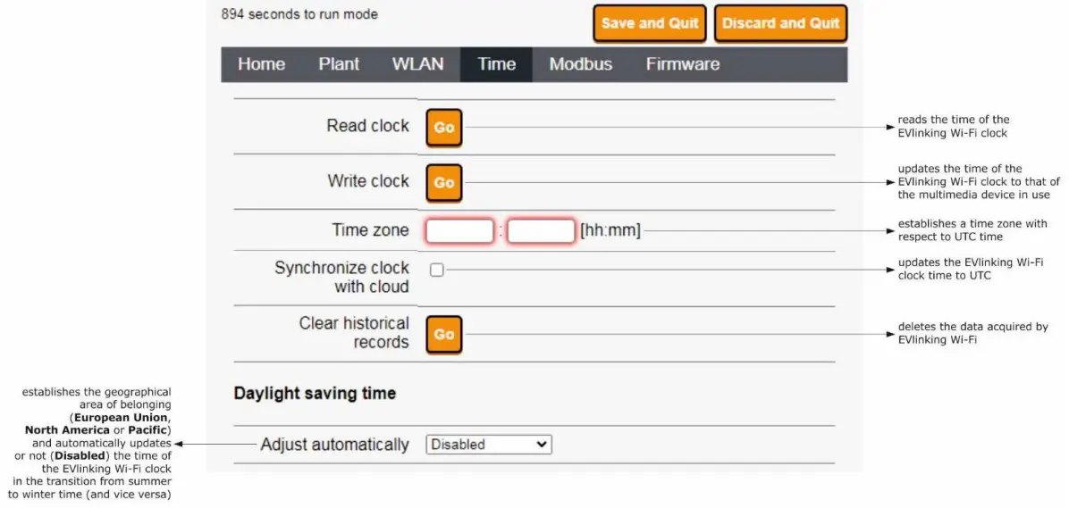
- Select the Time screen on the EVlinking Wi-Fi control panel.

- Select the Modbus screen on the EVlinking Wi-Fi control panel.
 If Modbus TCP communication is not enabled, the device will only work with EPoCA compatible controllers.
If you want to enable Modbus TCP communication, select the checkbox Enable Modbus TCP.
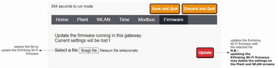
- Select the Firmware screen on the EVlinking Wi-Fi control panel.

- Disconnect the controller and disconnect the independent EVlinking Wi-Fi power supply, if used, from the power source.
- Power up the controller.
- Connect the independent EVlinking Wi-Fi power supply, if used, to the power source.
 If the scan detects more than one network called Epoca, make sure only one EVlinking Wi-Fi is being powered.
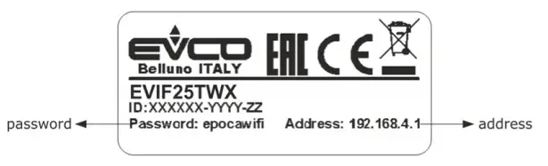
 If the IP addresses are statically assigned, select the Static button.
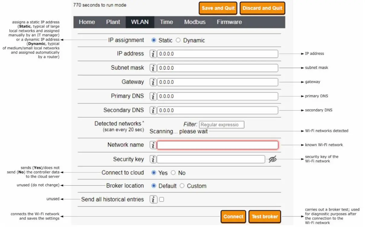
 If Modbus TCP communication is not enabled, the device will only work with EPoCA compatible controllers.
5.2 Description of the EVlinking Wi-Fi LEDs
| LED | ON | OFF | SLOW FLASH | RAPID FLASH |
| red (MODBUS communication status) | – | no MODBUS activity | MODBUS activity | – |
| green (Wi-Fi communication status) | connection with both the Wi-Fi network and the cloud server | no connection with the Wi-Fi network | connection with the Wi-Fi network, no connection with the cloud server |
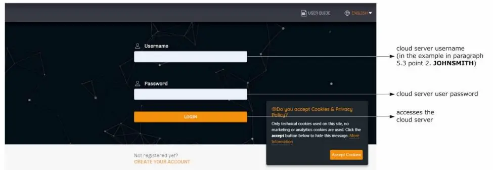
5.3 First access to the cloud server
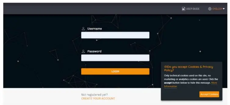
- Open the web browser on the multimedia device and open the web page epoca.cloud. The Login screen will be displayed.

- Select CREATE NEW ACCOUNT. The New account screen will be displayed.

- Select REGISTER. The Account created OK screen will be displayed.


SUBSEQUENT USES
![]() N.B.
N.B.
Any modifications to the configuration of EVlinking Wi-Fi must be made on site on all the EVlinking Wi-Fi devices in the same plant
6.1 Subsequent uses of EVlinking Wi-Fi
- Scan the Wi-Fi networks using the multimedia device and identify a network called Epoca followed by 6 alphanumeric characters and the name of the device, for example Epoca279A8E Cold room.

- Connect to the Epoca network.
In the Security key field enter the password found on the label of the EVlinking Wi-Fi (typically epocawifi). - Open the web browser on the multimedia device.
Enter the address found on the label of the EVlinking Wi-Fi (typically 192.168.4.1) in the address bar.
- The Login screen will be displayed.

6.2 Subsequent accesses to the cloud server
- Open the web browser on the multimedia device and open the web page epoca.cloud. The Login screen will be displayed.

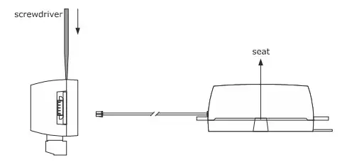
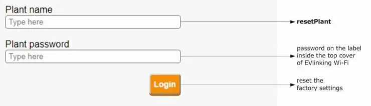
RESETTING THE FACTORY SETTINGS
![]() N.B.
N.B.
Resetting the factory settings deletes the settings on the Plant and WLAN screens but does not cancel the data recorded by the EVlinking Wi-Fi data logger.
- Disconnect the controller and any independent power supply to EVlinking Wi-Fi from the power source.
- Remove the top cover of EVlinking Wi-Fi by gently applying pressure with a screwdriver in the slot.

- Make a note of the password on the label inside the top cover of EVlinking Wi-Fi.

- Click the top cover of EVlinking Wi-Fi back into place.
- Power up the controller and connect the independent EVlinking Wi-Fi power supply, if used, to the power source.
- Scan the Wi-Fi networks using the multimedia device and identify a network called Epoca followed by 6 alphanumeric characters and the name of the device, for example Epoca279A8E Cold room.

- Connect to the Epoca network.
In the Security key field enter the password found on the label of the EVlinking Wi-Fi (typically epocawifi). - Open the web browser on the multimedia device.
Enter the address found on the label of the EVlinking Wi-Fi (typically 192.168.4.1) in the address bar.
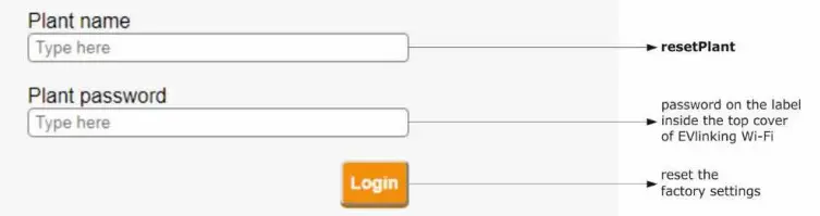
- The Login screen will be displayed.
Type in resetPlant in the Plant name field. Enter the password found on the label inside the top cover of EVlinking Wi-Fi in the Plant password field.
TECHNICAL SPECIFICATIONS
| Housing | black, self-extinguishing |
| Category of heat and fire resistance | D |
| Measurements | |
| for EVIF25TWX | 176.0 x 30.0 x 25.0 mm (6 15/16 x 1 3/16 x 1 in) |
| for EVIF25SWX | 56.0 x 30.0 x 25.0 mm (2 3/16 x 1 3/16 x 1 in) |
| Mounting method for the device | on a hard surface with a cable tie (provided) |
| Degree of protection provided by the casing | IP00 |
| Connection method | |
| for EVIF25TWX | plug-in screw terminal block for wires up to 1.5 mm², Pico-Blade connector |
| for EVIF25SWX | plug-in screw terminal block for wires up to 1.5 mm² |
| Maximum permitted length for connection cables | |
| power supply: 10 m (32.8 ft) | RS-485 MODBUS port: 1000 m (3280 ft) |
| Operating temperature | from 0 to 55 °C (from 32 to 131 °F). |
| Storage temperature | from -25 to 70 °C (from -13 to 158 °F) |
| Operating humidity | relative humidity without condensate from 10 to 90 % |
| Compliance | |
| RoHS 2011/65/EC | WEEE 2012/19/EU |
| REACH (EC) Regulation no. 1907/2006 | RED 2014/53/EU |
| Power supply | powered by the controller (depending on the type of controller) or independently powered 12 VAC ±15% or 15 VDC ±15%, 50/60 Hz (±3 Hz), max. 3.2 VA/2W |
| Software class and structure | A |
| Clock | secondary lithium battery |
| Clock drift | ≤ 60 s/month at 25 °C (77 °F) |
| Clock battery autonomy in the absence of a power supply | > 6 months at 25 °C (77 °F) |
| Clock battery charging time | 24 h (the battery is charged by the power supply of the device or by the independent power supply) for correct operation, the battery must be fully charged at least once a year |
| Displays | |
| MODBUS communication status LED | Wi-Fi communication status LED |
| Communications ports | |
| for EVIF25TWX | TTL MODBUS |
| for EVIF25SWX | RS-485 MODBUS |
| Connectivity | Wi-Fi |
| Wi-Fi output power (EIRP) | 11b: 67.5 mW and 11g: 71.1 mW, 11n (HT20) 56.5 mW |
| Wi-Fi frequency range | 2,412… 2,472 GHz |
| Security protocols | open, WEP, WPA/WPA2 Personal aka PSK |
| Encryption methods | TKIP, CCMP |
| Unsupported modes | mixed WPA/WPA2 PSK using TKIP + CCMP WPA/WPA2 Enterprise aka EAP |
SIMPLIFIED EU DECLARATION OF CONFORMITY
EVCO S.p.A. declares that the type of radio equipment:
– EVIF25TWX
– EVIF25SWX
complies with directive 2014/53/EU and directive 2011/65/EU.
The full text of the EU declaration of conformity is available at the following internet address: https://www.evco.it/en/16434-evlinking-wi-fi
N.B.
The device must be disposed of according to local regulations governing the collection of electrical and electronic equipment.
This document and the solutions contained therein are the intellectual property of EVCO and thus protected by the Italian Intellectual Property Rights Code (CPI). EVCO imposes an absolute ban on the full or partial reproduction and disclosure of the content other than with the express approval of EVCO. The customer (manufacturer, installer or end user) assumes all responsibility for the configuration of the device. EVCO accepts no liability for any possible errors in this document and reserves the right to make any changes, at any time without prejudice to the essential functional and safety features of the equipment.
![]() EVCO S.p.A.
EVCO S.p.A.
EVlinking Wi-Fi
Installer manual ver. 4.1 rev. B
PT – 35/22
Code 144IF25TWXE414
EVlinking Wi-Fi Installer manual ver. 4.1 Code 144IF25TWXE414
EVCO S.p.A.
Via Feltre 81, 32036 Medico (BL) ITALY
phone +39 0437 8422 fax +39 0437 83648
email [email protected]
web www.evco.it


